EP1247996B1 - Assemblage de valves avec un câblage comprenant un câble plat - Google Patents
Assemblage de valves avec un câblage comprenant un câble plat Download PDFInfo
- Publication number
- EP1247996B1 EP1247996B1 EP20010108666 EP01108666A EP1247996B1 EP 1247996 B1 EP1247996 B1 EP 1247996B1 EP 20010108666 EP20010108666 EP 20010108666 EP 01108666 A EP01108666 A EP 01108666A EP 1247996 B1 EP1247996 B1 EP 1247996B1
- Authority
- EP
- European Patent Office
- Prior art keywords
- connection means
- cable
- electrical connection
- arrangement according
- valve
- Prior art date
- Legal status (The legal status is an assumption and is not a legal conclusion. Google has not performed a legal analysis and makes no representation as to the accuracy of the status listed.)
- Expired - Lifetime
Links
- 239000004020 conductor Substances 0.000 claims description 16
- 230000000694 effects Effects 0.000 claims 1
- 238000005516 engineering process Methods 0.000 description 5
- 238000006073 displacement reaction Methods 0.000 description 3
- 239000012530 fluid Substances 0.000 description 3
- 238000009413 insulation Methods 0.000 description 3
- 230000015572 biosynthetic process Effects 0.000 description 2
- 230000003247 decreasing effect Effects 0.000 description 2
- 230000000295 complement effect Effects 0.000 description 1
- 238000011161 development Methods 0.000 description 1
- 230000018109 developmental process Effects 0.000 description 1
- 238000010616 electrical installation Methods 0.000 description 1
- 238000007373 indentation Methods 0.000 description 1
- 238000009434 installation Methods 0.000 description 1
- 230000007935 neutral effect Effects 0.000 description 1
- 230000000149 penetrating effect Effects 0.000 description 1
Images



Classifications
-
- F—MECHANICAL ENGINEERING; LIGHTING; HEATING; WEAPONS; BLASTING
- F15—FLUID-PRESSURE ACTUATORS; HYDRAULICS OR PNEUMATICS IN GENERAL
- F15B—SYSTEMS ACTING BY MEANS OF FLUIDS IN GENERAL; FLUID-PRESSURE ACTUATORS, e.g. SERVOMOTORS; DETAILS OF FLUID-PRESSURE SYSTEMS, NOT OTHERWISE PROVIDED FOR
- F15B13/00—Details of servomotor systems ; Valves for servomotor systems
- F15B13/02—Fluid distribution or supply devices characterised by their adaptation to the control of servomotors
- F15B13/06—Fluid distribution or supply devices characterised by their adaptation to the control of servomotors for use with two or more servomotors
- F15B13/08—Assemblies of units, each for the control of a single servomotor only
- F15B13/0803—Modular units
- F15B13/0832—Modular valves
- F15B13/0839—Stacked plate type valves
-
- F—MECHANICAL ENGINEERING; LIGHTING; HEATING; WEAPONS; BLASTING
- F15—FLUID-PRESSURE ACTUATORS; HYDRAULICS OR PNEUMATICS IN GENERAL
- F15B—SYSTEMS ACTING BY MEANS OF FLUIDS IN GENERAL; FLUID-PRESSURE ACTUATORS, e.g. SERVOMOTORS; DETAILS OF FLUID-PRESSURE SYSTEMS, NOT OTHERWISE PROVIDED FOR
- F15B13/00—Details of servomotor systems ; Valves for servomotor systems
- F15B13/02—Fluid distribution or supply devices characterised by their adaptation to the control of servomotors
- F15B13/06—Fluid distribution or supply devices characterised by their adaptation to the control of servomotors for use with two or more servomotors
- F15B13/08—Assemblies of units, each for the control of a single servomotor only
- F15B13/0803—Modular units
- F15B13/0821—Attachment or sealing of modular units to each other
- F15B13/0825—Attachment or sealing of modular units to each other the modular elements being mounted on a common member, e.g. on a rail
-
- F—MECHANICAL ENGINEERING; LIGHTING; HEATING; WEAPONS; BLASTING
- F15—FLUID-PRESSURE ACTUATORS; HYDRAULICS OR PNEUMATICS IN GENERAL
- F15B—SYSTEMS ACTING BY MEANS OF FLUIDS IN GENERAL; FLUID-PRESSURE ACTUATORS, e.g. SERVOMOTORS; DETAILS OF FLUID-PRESSURE SYSTEMS, NOT OTHERWISE PROVIDED FOR
- F15B13/00—Details of servomotor systems ; Valves for servomotor systems
- F15B13/02—Fluid distribution or supply devices characterised by their adaptation to the control of servomotors
- F15B13/06—Fluid distribution or supply devices characterised by their adaptation to the control of servomotors for use with two or more servomotors
- F15B13/08—Assemblies of units, each for the control of a single servomotor only
- F15B13/0803—Modular units
- F15B13/0846—Electrical details
- F15B13/0853—Electric circuit boards
-
- F—MECHANICAL ENGINEERING; LIGHTING; HEATING; WEAPONS; BLASTING
- F15—FLUID-PRESSURE ACTUATORS; HYDRAULICS OR PNEUMATICS IN GENERAL
- F15B—SYSTEMS ACTING BY MEANS OF FLUIDS IN GENERAL; FLUID-PRESSURE ACTUATORS, e.g. SERVOMOTORS; DETAILS OF FLUID-PRESSURE SYSTEMS, NOT OTHERWISE PROVIDED FOR
- F15B13/00—Details of servomotor systems ; Valves for servomotor systems
- F15B13/02—Fluid distribution or supply devices characterised by their adaptation to the control of servomotors
- F15B13/06—Fluid distribution or supply devices characterised by their adaptation to the control of servomotors for use with two or more servomotors
- F15B13/08—Assemblies of units, each for the control of a single servomotor only
- F15B13/0803—Modular units
- F15B13/0846—Electrical details
- F15B13/0857—Electrical connecting means, e.g. plugs, sockets
-
- F—MECHANICAL ENGINEERING; LIGHTING; HEATING; WEAPONS; BLASTING
- F15—FLUID-PRESSURE ACTUATORS; HYDRAULICS OR PNEUMATICS IN GENERAL
- F15B—SYSTEMS ACTING BY MEANS OF FLUIDS IN GENERAL; FLUID-PRESSURE ACTUATORS, e.g. SERVOMOTORS; DETAILS OF FLUID-PRESSURE SYSTEMS, NOT OTHERWISE PROVIDED FOR
- F15B13/00—Details of servomotor systems ; Valves for servomotor systems
- F15B13/02—Fluid distribution or supply devices characterised by their adaptation to the control of servomotors
- F15B13/06—Fluid distribution or supply devices characterised by their adaptation to the control of servomotors for use with two or more servomotors
- F15B13/08—Assemblies of units, each for the control of a single servomotor only
- F15B13/0803—Modular units
- F15B13/0846—Electrical details
- F15B13/0867—Data bus systems
-
- F—MECHANICAL ENGINEERING; LIGHTING; HEATING; WEAPONS; BLASTING
- F15—FLUID-PRESSURE ACTUATORS; HYDRAULICS OR PNEUMATICS IN GENERAL
- F15B—SYSTEMS ACTING BY MEANS OF FLUIDS IN GENERAL; FLUID-PRESSURE ACTUATORS, e.g. SERVOMOTORS; DETAILS OF FLUID-PRESSURE SYSTEMS, NOT OTHERWISE PROVIDED FOR
- F15B13/00—Details of servomotor systems ; Valves for servomotor systems
- F15B13/02—Fluid distribution or supply devices characterised by their adaptation to the control of servomotors
- F15B13/06—Fluid distribution or supply devices characterised by their adaptation to the control of servomotors for use with two or more servomotors
- F15B13/08—Assemblies of units, each for the control of a single servomotor only
- F15B13/0803—Modular units
- F15B13/0875—Channels for electrical components, e.g. for cables or sensors
Definitions
- the invention relates to a valve arrangement with a plurality electrically actuated valve units, each first electrical connection means for supplying electrical Have actuation signals and the formation of a valve assembly are consecutively lined up, the first electrical connection means a first connection means row form and with second electrical connection means are contacted on flexible wiring harnesses of an electrical Signal distribution device for the actuation signals are arranged by the contiguous harnesses one laid parallel to the first row of connection means flexible ribbon cable are formed, with which to the second electrical connection means equipped cable end decreasing from one edge of the cable to the other Are formed length and with a piece far from each other separate end sections to the respectively assigned second electrical connection means.
- valve arrangement is described in DE 199 01 880 A. out.
- the valve units are located side by side alongside lined up and receive their electrical actuation signals via a ribbon cable, the cable strands of led individual plug-like first connection means are, which with complementary second connection means of Valve units are contacted.
- the first connection means are attached to a lid, which is installed before the individual Valve units attached to the valve assembly becomes. Since the electrical installation is relatively complex, the present invention is based on the object simplify electrical connection technology.
- connection means are still under formation a second row of connecting means on the parallel fixed to the first connecting means row extending support bar, however, by attaching the support bar to the Valve assembly a simultaneous contacting of all first and second connection means pairs.
- the one that is characterized by different cable lengths Length section of the ribbon cable preferably extends at least approximately over the entire length of the first Connection means row.
- the arrangement is particularly so hit that, based on the laying direction of the Ribbon cable, the shortest cable harness to the first arranged Valve unit and the longest cable harness to the last arranged valve unit leads.
- the ribbon cable is expediently arranged such that the first row of connection means is in the area one of the two cable edges of the ribbon cable is located and preferably extends along the edge of the cable, to which the shorter cable harnesses are assigned.
- connection unit On the opposite of the second electrical connection means The end of the ribbon cable is conveniently located a collective connection unit on which all cable strands are connected together and via which, for example the connection to an extension of the valve assembly provided connection module of the valve arrangement can be made.
- the wiring effort is particularly low if all second connection means by a common Neutral conductors are connected to each other as a component of the ribbon cable or be formed separately from this can.
- a lid-like configuration is recommended for the support strip, so that they run the ribbon cable along at least the covers most of its length.
- connection means are expediently on individual Holders fixed, then the attachment to the Support strip is carried out.
- This indirect attachment has the advantage that the holder can act as an adapter, which differ as required with connection means Have the design equipped.
- valve arrangement 1 shown as an example contains one Variety of valve units 2 in one by a double arrow clarified linear alignment 3 in succession are arranged.
- Each valve unit 2 has a longitudinal axis 4 and is arranged that the longitudinal axis 4 is perpendicular to the direction of alignment 3 runs. All longitudinal axes 4 are parallel aligned with each other. In addition, the valve units 2 placed alongside each other.
- valve units 2 are preferably flat like disks trained so that their disc planes are rectangular extend to the direction of alignment 3.
- valve units 2 mounted on the side form a total designated by reference numeral 6 valve assembly, within the the valve units 2 are combined in a packet.
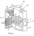
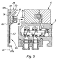
- valve 3 and 5 each show a valve unit 2 in Cut in a coincident with the disc plane Cutting plane. 4 is a single valve unit 2 shown.
- valve unit 2 of the valve assembly 6 is in each case preferably also disk-shaped trained final module 7a, 7b attached.
- End modules 7a, 7b are anchored tie rods, not shown, which enforce the valve assembly 6 and the termination modules 7a, 7b with the valve assembly 6 to form a package fit together firmly.
- each valve unit has 2 a main body shown in FIGS. 3 to 5 12, which forms the housing of a main valve 13.
- Main body 12 is located parallel to the longitudinal axis 4 extending receiving space 14, which has a piston-like design Valve slide 15 picks up.
- a feed channel 16 opens laterally into the receiving space 14, supplied via the fluidic pressure medium, in particular compressed air can be. Furthermore, it opens into the recording room 14 at least one discharge channel 17 - in the embodiment two such discharge channels 17 are provided, via which used pressure medium discharged and in the case of compressed air can be vented.
- Fluidic pressure medium supplied via the feed channel 16 can be done by positioning the valve spool accordingly 15 optionally directed into one of the two working channels 18, 19 be while at the same time from the other working channel Pressure medium to one of the discharge channels 17 is derived. On In this way, a 5/2 valve function known per se can be performed realize.
- valve units 2 of the supply channels 16 and discharge channels 17 each at right angles completely penetrated to the disc level. Similar Channels of adjacent valve units 2 are aligned, the aligned supply channels 16 one the valve assembly in the line-up direction 3 penetrating collective feed channel form and the aligned discharge channels 17 each have a parallel to the collecting feed channel Form collective discharge channel (not shown).
- Termination module 7b is one with an opening to the outer surface Feed connection opening 24 equipped through which for the Operation of the valve assembly 1 used pressure medium fed can be. Alternatively or additionally, this can be Supply connection opening 24 also on the front termination module 7a. Furthermore, at least one of the connection modules 7a, 7b per collective discharge channel with one not closer shown discharge connection opening equipped via the the used print medium can be removed.
- each Valve unit is thus individually able to connect the connected Actuator by supplying and removing fluid in one desired way to control.
- Each valve unit 2 has in addition to the main valve 13 via an electrically activatable valve drive 27 for specification the switching position of the main valve 13.
- valve drive 27 for specification the switching position of the main valve 13.
- the valve drives 27 are in particular around electromagnetically operated solenoid valves or Piezo valves, which act as pilot valves with respect to each associated main valve 13 work. So is through the valve actuators 27, for example, the fluid application of the associated Valve slide 15 for the purpose of obtaining the desired one Switch position controlled.
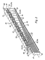
- the valve drives 27 receive the necessary for their operation electrical actuation signals via an electrical Signal distribution device 28, which is separated in FIG. 2 is shown.
- the electrical signal distribution device 28 is designed as part of the valve assembly 1 and conducts electrical actuation signals to the valve drives 27 further connected to an electrical connection unit 32 of a Connection module 33 of the valve assembly 1 can be fed. The feed takes place through a not shown external electronic control device.
- connection module 33 is an extension of the valve assembly 6 arranged after the front termination module 7a and to the end face opposite the valve assembly 6 of the front end module 7a firmly attached.
- Each valve unit 2 is for supplying the electrical actuation signals with first electrical connection means 34 equipped, in the embodiment of plug contacts are formed.
- the first are within the valve units 2 electrical connection means 34 placed identically, so that due to the series arrangement of the valve units 2 overall a first row of connection means indicated in FIG. 1 35 form, the alignment 36 parallel to that (3) of the valve units 2 runs.
- connection means 34 There is one on the electrical signal distribution device 28 number corresponding to the number of first connection means 34 second electrical connection means 37 are provided, one form linear second connecting means row 38, which are parallel runs to the first row of connection means 35.
- the first and second electrical connection means 34, 37 are assigned in pairs and are in pairs with each other electrically contacted.
- the second are electrical Connection means 37 in the embodiment of plug-in recesses formed, in which the plug-like first electrical Connection means 34 can be inserted, in particular an embodiment in so-called insulation displacement technology can be present.
- the signal distribution device 28 For establishing the connection between the electrical connection unit 32 of the connection module 33 and the individual second electrical connection means 37 is the signal distribution device 28 with a flexible ribbon cable 42 fitted. This contains a large number parallel to each other extending cable harnesses 43 each with an electrical Conductor and an insulating sheath, the sheaths all cable strands 43 connected in one piece are.
- Every second electrical connection means 37 is at the rear end of one of the harnesses 43 connected.
- the ribbon cable 42 runs alongside the valve assembly 6 with the first and second row of connection means 35, 38 parallel alignment.
- the dash-dotted in Fig. 3 marked extension plane 44 of the ribbon cable 42 runs in particular parallel to the adjacent outer surface section 45 of the valve assembly 6 and preferably at right angles to the longitudinal axes 4 of the valve units 2.
- the ribbon cable 42 ends at least essentially same length of individual wiring harnesses 43, which are common on a preferably connector-shaped collective connection unit 47 are connected.
- the latter has elongated ones Shape and is perpendicular to the longitudinal axis 48 of the Ribbon cable 42. It is used to produce a detachable Connection to the electrical connection unit 32, to which Purpose with one provided on the connection module 33 Connection counterpart 52 can be contacted, which is suitable via a trained conductor arrangement 53 with the electrical Connection unit 32 is connected.
- the ladder arrangement 53 can contain a circuit board which is accommodated in the connection module 33 and is equipped with electronic components is required for correct signal distribution or make sense.
- Such a configuration of the ribbon cable 42 leaves achieve yourself, for example, by consistently the same length of harness Ribbon cable pulls that one at an end at an angle cuts.
- To produce second connection means 37 are the cable harnesses 43 to those assigned to the rear cable end 54 End sections 57 a bit, so along a certain Longitudinal section, separated from each other. This can be done very well simply by simply wrapping the Ribbon cable 42 between the individual cable strands 43 severed.
- the end portions 57 of the harnesses 43 are fanned out or spliced in this way, so that adjust flexibly movable end portions 57 while in remaining a firm cohesion of the cable strands 43 within of the ribbon cable 42 is present.
- the ribbon cable 42 is expediently designed in this way and arranged to be different cable lengths distinctive length at least approximately and in particular completely along the entire length the first and second row of connection means 35, 38 extends. Such an arrangement can be seen in FIG. 2. It is the arrangement of the second row of connection means 38 by the Placement of the first row of connection means 35 specified.
- connection means 35, 38 there are first and second rows of connection means 35, 38 in the area a cable edge of the ribbon cable 42 and extend preferably along the edge of the cable 56 through the shorter cable harnesses 43 is defined.
- the separate end portions 57 of the wire harnesses 43 are preferably each of those second electrical Connection means 37 performed with respect to the Longitudinal axis 48 of the ribbon cable 42 at about the same height lie like the relevant end section 57.
- the shortest cable harness 43, 43a is connected to those second electrical ones Connection means 37, 37a connected to the front Cable end 46 is closest.
- the second longest harness is with the next second electrical connection means 37 the second row of connection means 38 contacted. This sets continues to the last second electrical connection means 37, 37b, the one with the longest cable harness 43, 43b are electrically connected.
- the second electrical connection means 37 attached directly to the ends of the cable strands 43 can be what turns out to be much easier and proves more reliable than a possible connection in one Intermediate area of the cable strands when the ribbon cable 42 would be consistently trained.
- the individual second electrical connection means 37 leads only one cable harness 43 in the exemplary embodiment of the ribbon cable 42, which is used to supply the actuation signals serves. However, there is also a common return conductor 58 provided the all second connection means 37 connects with each other.
- the return conductor 58 is composed of a A plurality of conductor strands 59 together, a first Conductor strand from the collective connection unit 47 to the foremost second electrical connection means 37a and from there through further conductor strings 59 individual connections between successive second electrical Connection means 37 are made.
- the first The conductor strand is preferably part of the ribbon cable 42 and formed by the same wiring harness Is configured in the same way as the other cable strands 43.
- the common return conductor 58 can be connected to the Ribbon cable 42 can also be formed separately, so that it is not part of the ribbon cable 42.
- the second electrical Connection means 37 can be made using suitable connection technology, especially insulation displacement technology, with the ribbon cable 42 and the common return conductor 58 are electrically connected his.
- the common return conductor can be made using insulation displacement technology 58 are looped through the respective connector. A possible additional connection point or the merging the common return conductor 58 can thus be omitted.
- the first and second electrical connection means 34, 37 expediently aligned such that their arrow 63 illustrated direction of contact perpendicular to Extension plane 44 of the ribbon cable 42 runs.
- the signal distribution device 28 of the exemplary embodiment is characterized by a very good handling.
- she contains one parallel to the first row of connection means 35 extending support bar 64 on which the second connection means 37 are held releasably.
- the support bar 64 is preferred formed like a lid and has a U-shaped cross section, wherein the interior 65 defined by the U cross section for Recording of the ribbon cable 42 is provided (see. Fig. 3).
- the support bar 64 is along with the U-opening ahead the valve assembly 6 is attached, being axially on both sides towered over and with the corresponding end sections 66 is fixed to the termination modules 7a, 7b.
- the latter will achieved in particular in that the two longitudinal Support strip legs 67a, 67b in the context of snap connections with locking counterparts 68a, 68b of the termination modules 7a, 7b in Intervention can be brought.
- the support strip leg oriented upward in the exemplary embodiment 67a is not only used to fasten the support bar 64 on the termination modules 7a, 7b, but simultaneously to hold the second connection means 37 the relevant support strip leg 67a as a holding rail 72, to which the second electrical connection means 37 from one End face of the support bar 64 pushed one after the other become. It would be possible to use the second electrical To fix connection means 37 directly to the holding rail 72, but you have an indirect in the embodiment Attachment selected.
- the second electrical connection means are located here 37 on individual modular holders 73, which in turn in the manner described on the support rail 72 are fixed. They have a groove-like back Indentation 74 into which the holding rail 72 engages in a form-fitting manner.
- the axial position of the holders 73 with respect to the holding rail 72 can be secured, for example, by sufficient frictional forces become.
- the ribbon cable inserted into the interior 65 of the support bar 64 42 can also be attached to the support bar if required 64 can be fixed. Im attached to the valve assembly 6 Condition, the interior 65 is closed all around, so that the ribbon cable 42 along at least most of it its length to the environment is covered. Only on the The ribbon cable protrudes at the front end of the support bar 64 42 a little way out and carries the collective connection unit there 47th
- Making the electrical connections between the different pairs of first and second electrical connection means 34, 37 can be used for all valve units 2 done simultaneously by the second electrical connection means 37 lined up on the support bar 64 according to FIG. 2 and then together with this to the valve assembly can be applied, the front of the second row of connection means 38 protruding end portions 66 of the Support bar 64 with the termination modules 7a, 7b a detachable Make a latching connection.
Landscapes
- Engineering & Computer Science (AREA)
- Physics & Mathematics (AREA)
- Fluid Mechanics (AREA)
- Mechanical Engineering (AREA)
- General Engineering & Computer Science (AREA)
- Multi-Conductor Connections (AREA)
- Magnetically Actuated Valves (AREA)
Claims (16)
- Agencement de soupapes, avec une pluralité d'unités de soupape (2) actionnables électriquement, qui comportent chacune des premiers moyens de branchement électriques (34) pour l'amenée de signaux d'actionnement électriques et qui sont juxtaposées les unes derrière les autres pour former un bloc-soupapes (6), les premiers moyens de branchement électriques (34) formant une première rangée de moyens de branchement (35) et étant en contact avec des deuxièmes moyens de branchement électriques (37) qui sont disposés sur des faisceaux de câbles (43) flexibles d'un dispositif électrique (28) de distribution de signaux (28) pour les signaux d'actionnement, lesquels sont formés par les faisceaux de câbles (43) réunis d'un câble plat (42) flexible posé parallèlement à la première rangée de moyens de branchement (35), leur longueur diminuant d'un bord de câble à l'autre (55, 56), vers l'extrémité de câble (54) équipée des deuxièmes moyens de branchement électriques (37), et s'étendant, sur une certaine distance, par des tronçons terminaux (57) séparés les uns des autres, vers les deuxièmes moyens de branchement électriques (37) associés, le dispositif électrique de distribution des signaux (28) comportant une baguette de support (64) s'étendant parallèlement à la première rangée de moyens de branchement (35), sur laquelle sont maintenus les deuxièmes moyens électriques de branchement (37) en formant une deuxième rangée de moyens de branchement (38), caractérisé par une forme de réalisation qui, lorsque la baguette de support (64) est placée contre les unités de soupape (2) réunies en bloc-soupapes, provoque une mise en contact simultanée de toutes les paires des premiers et des deuxième moyens de branchement électriques (34, 37).
- Agencement de soupapes selon la revendication 1, caractérisé en ce que le tronçon de longueur, pourvu de différentes longueurs de faisceaux de câbles, du câble plat (42), s'étend approximativement sur toute la longueur des premiers moyens de branchement (35).
- Agencement de soupapes selon la revendication 1 ou 2, caractérisé en ce que la première rangée de moyens de branchement (35) est disposée dans la zone d'un bord de câble (56) du câble plat (42).
- Agencement de soupapes selon la revendication 3, caractérisé en ce que la première rangée de moyens de branchement (35) s'étend le long du bord de câble (56) auquel sont associés les faisceaux de câbles (43) plus courts.
- Agencement de soupapes selon l'une des revendications 1 à 4, caractérisé en ce que les tronçons terminaux (57) séparés les uns des autres des faisceaux de câbles (43) sont reliés respectivement à des deuxièmes moyens de branchement électriques (37) qui se situent approximativement à la même hauteur que le tronçon terminal du faisceau de câbles (57) concerné, par rapport à la direction longitudinale du câble plat (42).
- Agencement de soupapes selon l'une des revendications 1 à 5, caractérisé en ce que les faisceaux de câbles (43) sont raccordés à l'extrémité de câble (46), opposée aux deuxième moyens de branchement électriques (37), à une unité de branchement collectif (47) commune.
- Agencement de soupapes selon l'une des revendications 1 à 6, caractérisé par un conducteur de retour (58) commun reliant entre eux tous les deuxièmes moyens de branchement électriques (37).
- Agencement de soupapes selon la revendication 7, caractérisé en ce que le conducteur de retour (58) commun est réalisé séparé du câble plat (42), les deuxièmes moyens de branchement électriques (37) étant avantageusement reliés électriquement par une technique de branchement appropriée, en particulier une technique à borne coupante, au câble plat (42) et au conducteur de retour (58) commun.
- Agencement de soupapes selon l'une des revendications 1 à 8, caractérisé en ce que les premiers et deuxièmes moyens de branchement électriques (34, 37) sont orientés de manière que la direction de mise en contact (63) s'étende perpendiculairement au plan d'étendue (44) du câble plat (42).
- Agencement de soupapes selon l'une des revendications 1 à 9, caractérisé en ce que le câble plat (42) est également fixé à la baguette de support (64).
- Agencement de soupapes selon l'une des revendications 1 à 10, caractérisé en ce que la baguette de support (64) est placée sur le côté longitudinal du bloc-soupapes (6), en étant fixée en particulier par une liaison à encliquetage.
- Agencement de soupapes selon l'une des revendications 1 à 11, caractérisé en ce que la baguette de support (64) est réalisée à la manière d'un couvercle et recouvre le câble plat (42) le long d'au moins la plus grande partie de sa longueur.
- Agencement de soupapes selon l'une des revendications 1 à 12, caractérisé en ce que les deuxièmes moyens de branchement électriques (37) sont fixés sur des supports (73) individuels qui de leur côté sont fixés à la baguette de support (64).
- Agencement de soupapes selon l'une des revendications 1 à 13, caractérisé en ce que les deuxièmes moyens de branchement électriques (37) sont enfilés directement ou indirectement sur un rail de support (72) de la baguette de support (64).
- Agencement de soupapes selon l'une des revendications 1 à 14, caractérisé en ce que dans le prolongement du bloc-soupapes (6) est prévu un module de branchement (33) qui comporte une unité de branchement électrique (32), laquelle est reliée aux faisceaux de câbles (43) du câble plat (42).
- Agencement de soupapes selon l'une des revendications 1 à 15, caractérisé en ce que les unités de soupape (2) sont placées côte à côte dans le sens de la longueur et forment un bloc-soupapes (6) de type paquet.
Priority Applications (3)
| Application Number | Priority Date | Filing Date | Title |
|---|---|---|---|
| EP20010108666 EP1247996B1 (fr) | 2001-04-06 | 2001-04-06 | Assemblage de valves avec un câblage comprenant un câble plat |
| DE50103095T DE50103095D1 (de) | 2001-04-06 | 2001-04-06 | Ventilanordnung mit einer Kabelverbindung mittels Flachbandkabel |
| ES01108666T ES2221630T3 (es) | 2001-04-06 | 2001-04-06 | Disposicion de valvulas con una union de cable mediante un cable en forma de cinta plana. |
Applications Claiming Priority (1)
| Application Number | Priority Date | Filing Date | Title |
|---|---|---|---|
| EP20010108666 EP1247996B1 (fr) | 2001-04-06 | 2001-04-06 | Assemblage de valves avec un câblage comprenant un câble plat |
Publications (2)
| Publication Number | Publication Date |
|---|---|
| EP1247996A1 EP1247996A1 (fr) | 2002-10-09 |
| EP1247996B1 true EP1247996B1 (fr) | 2004-08-04 |
Family
ID=8177064
Family Applications (1)
| Application Number | Title | Priority Date | Filing Date |
|---|---|---|---|
| EP20010108666 Expired - Lifetime EP1247996B1 (fr) | 2001-04-06 | 2001-04-06 | Assemblage de valves avec un câblage comprenant un câble plat |
Country Status (3)
| Country | Link |
|---|---|
| EP (1) | EP1247996B1 (fr) |
| DE (1) | DE50103095D1 (fr) |
| ES (1) | ES2221630T3 (fr) |
Cited By (2)
| Publication number | Priority date | Publication date | Assignee | Title |
|---|---|---|---|---|
| DE102004009771A1 (de) * | 2004-02-28 | 2005-09-15 | Rexroth Mecman Gmbh | Ventileinheit mit wahlweise über eine serielle oder parallele Steuersignalübertragung ansteuerbaren Mehrwegeventilen |
| DE102004041256A1 (de) * | 2004-08-26 | 2006-03-16 | Bosch Rexroth Ag | Ventileinheit mit einzeln ausgebildeten Anschlussplatten zur Bildung eines Ventilträgersystems |
Families Citing this family (3)
| Publication number | Priority date | Publication date | Assignee | Title |
|---|---|---|---|---|
| DE102006051281C5 (de) * | 2006-10-25 | 2013-04-25 | Balluff Gmbh | Verteilervorrichtung |
| DE102006056554B4 (de) * | 2006-11-29 | 2009-07-30 | Erni Electronics Gmbh | Montagevorrichtung zur Aufnahme von Elektronikmodulen |
| CN108365592B (zh) * | 2018-04-02 | 2024-04-02 | 中国电建集团福建省电力勘测设计院有限公司 | 用于拼舱型预制舱的电缆转换箱及其接线方法 |
Family Cites Families (4)
| Publication number | Priority date | Publication date | Assignee | Title |
|---|---|---|---|---|
| DE9305574U1 (de) * | 1993-04-14 | 1993-06-17 | Herion-Werke Kg, 7012 Fellbach | Steuervorrichtung für Elektromagnetventile |
| JPH09133240A (ja) * | 1995-11-06 | 1997-05-20 | Smc Corp | 電磁弁組立体の給電装置 |
| SE520212C2 (sv) * | 1998-01-21 | 2003-06-10 | Mecman Ab Rexroth | Anordning vid rampmontage av fluidventiler |
| JP3729231B2 (ja) * | 1998-03-20 | 2005-12-21 | Nok株式会社 | マニホールドベース |
-
2001
- 2001-04-06 EP EP20010108666 patent/EP1247996B1/fr not_active Expired - Lifetime
- 2001-04-06 DE DE50103095T patent/DE50103095D1/de not_active Expired - Lifetime
- 2001-04-06 ES ES01108666T patent/ES2221630T3/es not_active Expired - Lifetime
Cited By (3)
| Publication number | Priority date | Publication date | Assignee | Title |
|---|---|---|---|---|
| DE102004009771A1 (de) * | 2004-02-28 | 2005-09-15 | Rexroth Mecman Gmbh | Ventileinheit mit wahlweise über eine serielle oder parallele Steuersignalübertragung ansteuerbaren Mehrwegeventilen |
| DE102004041256A1 (de) * | 2004-08-26 | 2006-03-16 | Bosch Rexroth Ag | Ventileinheit mit einzeln ausgebildeten Anschlussplatten zur Bildung eines Ventilträgersystems |
| DE102004041256B4 (de) * | 2004-08-26 | 2007-04-26 | Bosch Rexroth Ag | Ventileinheit mit mehreren elektrisch betätigten Ventilen |
Also Published As
| Publication number | Publication date |
|---|---|
| EP1247996A1 (fr) | 2002-10-09 |
| DE50103095D1 (de) | 2004-09-09 |
| ES2221630T3 (es) | 2005-01-01 |
Similar Documents
| Publication | Publication Date | Title |
|---|---|---|
| DE4230414C2 (de) | Elektro-pneumatische Steuereinrichtung | |
| DE10013192B4 (de) | Ventilanordnung | |
| DE3814485C2 (fr) | ||
| EP1013940B1 (fr) | Arrangement de soupape | |
| EP1710447B1 (fr) | Appareil de commande électro-fluidique | |
| EP2738396B1 (fr) | Agencement de vannes | |
| EP2354563B1 (fr) | Agencement de vannes | |
| EP1247996A1 (fr) | Assemblage de valves avec un câblage comprenant un câble plat | |
| DE3933942C2 (fr) | ||
| DE102005015426A1 (de) | Kopplungsventil | |
| DE19710459B4 (de) | Hilfsbetätigungsorgan für einen Anschlußblock | |
| EP2656443B1 (fr) | Module de liaison et système de module de liaison | |
| EP0924799B1 (fr) | Dispositif pour câbler des places de raccordement des composants des appareils ou des installations électriques | |
| DE3910913C2 (de) | Pneumatische oder hydraulische Ventileinheit | |
| DE19903030C1 (de) | Vorrichtung zur abisolierfreien Kontaktierung eines Flachkabels | |
| DE4438164A1 (de) | Antriebsvorrichtung | |
| DE29605984U1 (de) | Anschlußeinrichtung für Flachbandkabel | |
| WO2016008504A1 (fr) | Ensemble module | |
| DE10205470C1 (de) | Anschlusskontakt | |
| DE4320539A1 (de) | Leitungsdraht-Verbindungsklemme | |
| EP1284371B1 (fr) | Assemblage de valves sous forme de matrice | |
| DE9214301U1 (de) | Elektro-pneumatische Steuereinrichtung | |
| EP2412985A2 (fr) | Dispositif de distribution de fluides | |
| DE20105982U1 (de) | Ventilanordnung | |
| EP1391967A1 (fr) | Dispositif de connexion |
Legal Events
| Date | Code | Title | Description |
|---|---|---|---|
| PUAI | Public reference made under article 153(3) epc to a published international application that has entered the european phase |
Free format text: ORIGINAL CODE: 0009012 |
|
| AK | Designated contracting states |
Kind code of ref document: A1 Designated state(s): AT BE CH CY DE DK ES FI FR GB GR IE IT LI LU MC NL PT SE TR |
|
| AX | Request for extension of the european patent |
Free format text: AL;LT;LV;MK;RO;SI |
|
| 17P | Request for examination filed |
Effective date: 20021220 |
|
| 17Q | First examination report despatched |
Effective date: 20030310 |
|
| AKX | Designation fees paid |
Designated state(s): DE ES FR GB IT |
|
| GRAP | Despatch of communication of intention to grant a patent |
Free format text: ORIGINAL CODE: EPIDOSNIGR1 |
|
| GRAS | Grant fee paid |
Free format text: ORIGINAL CODE: EPIDOSNIGR3 |
|
| GRAA | (expected) grant |
Free format text: ORIGINAL CODE: 0009210 |
|
| AK | Designated contracting states |
Kind code of ref document: B1 Designated state(s): DE ES FR GB IT |
|
| REG | Reference to a national code |
Ref country code: GB Ref legal event code: FG4D Free format text: NOT ENGLISH |
|
| GBT | Gb: translation of ep patent filed (gb section 77(6)(a)/1977) |
Effective date: 20040804 |
|
| REG | Reference to a national code |
Ref country code: IE Ref legal event code: FG4D Free format text: GERMAN |
|
| REF | Corresponds to: |
Ref document number: 50103095 Country of ref document: DE Date of ref document: 20040909 Kind code of ref document: P |
|
| REG | Reference to a national code |
Ref country code: ES Ref legal event code: FG2A Ref document number: 2221630 Country of ref document: ES Kind code of ref document: T3 |
|
| REG | Reference to a national code |
Ref country code: IE Ref legal event code: FD4D |
|
| PLBE | No opposition filed within time limit |
Free format text: ORIGINAL CODE: 0009261 |
|
| STAA | Information on the status of an ep patent application or granted ep patent |
Free format text: STATUS: NO OPPOSITION FILED WITHIN TIME LIMIT |
|
| ET | Fr: translation filed | ||
| 26N | No opposition filed |
Effective date: 20050506 |
|
| PGFP | Annual fee paid to national office [announced via postgrant information from national office to epo] |
Ref country code: ES Payment date: 20130311 Year of fee payment: 13 |
|
| REG | Reference to a national code |
Ref country code: FR Ref legal event code: PLFP Year of fee payment: 15 |
|
| REG | Reference to a national code |
Ref country code: ES Ref legal event code: FD2A Effective date: 20150526 |
|
| PGFP | Annual fee paid to national office [announced via postgrant information from national office to epo] |
Ref country code: GB Payment date: 20150326 Year of fee payment: 15 |
|
| PG25 | Lapsed in a contracting state [announced via postgrant information from national office to epo] |
Ref country code: ES Free format text: LAPSE BECAUSE OF NON-PAYMENT OF DUE FEES Effective date: 20140407 |
|
| PGFP | Annual fee paid to national office [announced via postgrant information from national office to epo] |
Ref country code: IT Payment date: 20150423 Year of fee payment: 15 Ref country code: FR Payment date: 20150422 Year of fee payment: 15 |
|
| PGFP | Annual fee paid to national office [announced via postgrant information from national office to epo] |
Ref country code: DE Payment date: 20160311 Year of fee payment: 16 |
|
| GBPC | Gb: european patent ceased through non-payment of renewal fee |
Effective date: 20160406 |
|
| REG | Reference to a national code |
Ref country code: FR Ref legal event code: ST Effective date: 20161230 |
|
| PG25 | Lapsed in a contracting state [announced via postgrant information from national office to epo] |
Ref country code: GB Free format text: LAPSE BECAUSE OF NON-PAYMENT OF DUE FEES Effective date: 20160406 Ref country code: FR Free format text: LAPSE BECAUSE OF NON-PAYMENT OF DUE FEES Effective date: 20160502 |
|
| PG25 | Lapsed in a contracting state [announced via postgrant information from national office to epo] |
Ref country code: IT Free format text: LAPSE BECAUSE OF NON-PAYMENT OF DUE FEES Effective date: 20160406 |
|
| REG | Reference to a national code |
Ref country code: DE Ref legal event code: R119 Ref document number: 50103095 Country of ref document: DE |
|
| PG25 | Lapsed in a contracting state [announced via postgrant information from national office to epo] |
Ref country code: DE Free format text: LAPSE BECAUSE OF NON-PAYMENT OF DUE FEES Effective date: 20171103 |