EP1248226A2 - Gerät, Verfahren und Programm zum Vergleichen von Mustern - Google Patents
Gerät, Verfahren und Programm zum Vergleichen von Mustern Download PDFInfo
- Publication number
- EP1248226A2 EP1248226A2 EP20020007179 EP02007179A EP1248226A2 EP 1248226 A2 EP1248226 A2 EP 1248226A2 EP 20020007179 EP20020007179 EP 20020007179 EP 02007179 A EP02007179 A EP 02007179A EP 1248226 A2 EP1248226 A2 EP 1248226A2
- Authority
- EP
- European Patent Office
- Prior art keywords
- deformation
- graphic form
- examined
- estimating
- model
- Prior art date
- Legal status (The legal status is an assumption and is not a legal conclusion. Google has not performed a legal analysis and makes no representation as to the accuracy of the status listed.)
- Granted
Links
Images






Classifications
-
- G—PHYSICS
- G06—COMPUTING OR CALCULATING; COUNTING
- G06V—IMAGE OR VIDEO RECOGNITION OR UNDERSTANDING
- G06V10/00—Arrangements for image or video recognition or understanding
- G06V10/40—Extraction of image or video features
-
- G—PHYSICS
- G06—COMPUTING OR CALCULATING; COUNTING
- G06V—IMAGE OR VIDEO RECOGNITION OR UNDERSTANDING
- G06V10/00—Arrangements for image or video recognition or understanding
- G06V10/70—Arrangements for image or video recognition or understanding using pattern recognition or machine learning
- G06V10/74—Image or video pattern matching; Proximity measures in feature spaces
- G06V10/75—Organisation of the matching processes, e.g. simultaneous or sequential comparisons of image or video features; Coarse-fine approaches, e.g. multi-scale approaches; using context analysis; Selection of dictionaries
- G06V10/754—Organisation of the matching processes, e.g. simultaneous or sequential comparisons of image or video features; Coarse-fine approaches, e.g. multi-scale approaches; using context analysis; Selection of dictionaries involving a deformation of the sample pattern or of the reference pattern; Elastic matching
-
- G—PHYSICS
- G06—COMPUTING OR CALCULATING; COUNTING
- G06V—IMAGE OR VIDEO RECOGNITION OR UNDERSTANDING
- G06V10/00—Arrangements for image or video recognition or understanding
- G06V10/70—Arrangements for image or video recognition or understanding using pattern recognition or machine learning
- G06V10/74—Image or video pattern matching; Proximity measures in feature spaces
- G06V10/75—Organisation of the matching processes, e.g. simultaneous or sequential comparisons of image or video features; Coarse-fine approaches, e.g. multi-scale approaches; using context analysis; Selection of dictionaries
- G06V10/757—Matching configurations of points or features
Definitions
- the present invention relates to collation of image data and, more particularly, to a pattern collation device for identifying linear graphic forms such as fingerprints and characters and a pattern collating method thereof, and a pattern collation program.
- An object of the present invention is to solve the above-described conventional problems and provide a linear graphic form pattern collation device which is capable of strictly discriminating an applied graphic form even when it is deformed and a pattern collating method thereof, and a pattern collation program.
- the present invention enables the graphic form to be examined which is a graphic form as an object of examination and a model graphic form which is a graphic form based on which comparison is made to be strictly discriminated from each other by estimating deformation generated in the graphic form to be examined based on applied feature point information of the graphic form to be examined and applied feature point information of the model graphic form, correcting the estimated deformation and comparing the graphic form to be examined whose deformation has been corrected and the model graphic form to calculate similarity therebetween.
- a pattern collation device for comparing and collating a graphic form to be examined and a model graphic form as a graphic form based on which comparison is made, comprises deformation estimating means for estimating deformation generated in a graphic form to be examined which is a graphic form as an object of examination based on information about a feature point indicative of features in each of the graphic form to be examined in question and a model graphic form as a graphic form based on which comparison is made, and deformation correcting means for correcting the graphic form to be examined in question based on information about the deformation estimated by the deformation estimating means.
- the deformation estimating means correlates and pairs feature points in each of the graphic form to be examined and the model graphic form between which a difference in feature quantity indicative of a degree of features at the feature point is small and determines the contents of deformation of the graphic form to be examined which best match correspondences between the respective feature points to estimate deformation generated in the graphic form to be examined in question.
- the deformation estimating means selects the contents of deformation of the graphic form to be examined which best match correspondences between the respective feature points in each of the graphic form to be examined and the model graphic form from a plurality of deformation models indicative of the contents of deformation of image data which are prepared in advance.
- the deformation estimating means has information of a deformation model indicative of the contents of deformation of image data corresponding to a value designated by an individual parameter, and determines the contents of deformation of the graphic form to be examined by obtaining a value of each the parameter which provides the deformation model that best matches correspondences between the respective feature points in each of the graphic form to be examined and the model graphic form.
- the deformation estimating means re-estimates deformation using only feature point pairs left after excluding the paired feature points which go apart from each other by a distance equal to or greater than a predetermined threshold value when subjected to estimated deformation.
- the deformation estimating means changes the deformation model in question to re-estimate deformation when the scale of estimated deformation is larger than a predetermined threshold value.
- the deformation estimating means after estimating deformation of the graphic form to be examined as a whole, divides the graphic form to be examined in question into small regions to estimate the contents of deformation at each the small region.
- the deformation estimating means after estimating deformation of the graphic form to be examined as a whole, refers, with respect to each feature point pair in question, to information of the feature point pairs in the vicinity to estimate and correct deformation in the vicinity of each the feature point pair.
- the graphic form to be examined and the model graphic form at least either a fingerprint image or a palmprint image is used.
- a deformation correcting device for comparing a graphic form to be examined and a model graphic form as a graphic form based on which comparison is made to correct deformation, comprises deformation estimating means for estimating deformation generated in a graphic form to be examined which is a graphic form as an object of examination based on information about a feature point indicative of features in each of the graphic form to be examined in question and a model graphic form as a graphic form based on which comparison is made, and deformation correcting means for correcting the graphic form to be examined in question based on information about the deformation estimated by the deformation estimating means.
- the deformation estimating means correlates and pairs feature points in each of the graphic form to be examined and the model graphic form between which a difference in feature quantity indicative of a degree of features at the feature point is small and determines the contents of deformation of the graphic form to be examined which best match correspondences between the respective feature points to estimate deformation generated in the graphic form to be examined in question.
- the deformation estimating means selects the contents of deformation of the graphic form to be examined which best match correspondences between the respective feature points in each of the graphic form to be examined and the model graphic form from a plurality of deformation models indicative of the contents of deformation of image data which are prepared in advance.
- the deformation estimating means has information of a deformation model indicative of the contents of deformation of image data corresponding to a value designated by an individual parameter, and determines the contents of deformation of the graphic form to be examined by obtaining a value of each the parameter which provides the deformation model that best matches correspondences between the respective feature points in each of the graphic form to be examined and the model graphic form.
- the deformation estimating means re-estimates deformation using only feature point pairs left after excluding the paired feature points which go apart from each other by a distance equal to or greater than a predetermined threshold value when subjected to estimated deformation.
- the deformation estimating means changes the deformation model in question to re-estimate deformation when the scale of estimated deformation is larger than a predetermined threshold value.
- the deformation estimating means after estimating deformation of the graphic form to be examined as a whole, divides the graphic form to be examined in question into small regions to estimate the contents of deformation at each the small region.
- the deformation estimating means after estimating deformation of the graphic form to be examined as a whole, refers, with respect to each feature point pair in question, to information of the feature point pairs in the vicinity to estimate and correct deformation in the vicinity of each the feature point pair.
- the graphic form to be examined and the model graphic form at least either a fingerprint image or a palmprint image is used.
- a pattern collating method of comparing and collating a graphic form to be examined and a model graphic form as a graphic form based on which comparison is made comprising the steps of the deformation estimating step of estimating deformation generated in a graphic form to be examined which is a graphic form as an object of examination based on information about a feature point indicative of features in each of the graphic form to be examined in question and a model graphic form as a graphic form based on which comparison is made, and the deformation correcting step of correcting the graphic form to be examined in question based on information about the estimated deformation.
- feature points in each of the graphic form to be examined and the model graphic form between which a difference in feature quantity indicative of a degree of features at the feature point is small are correlated and paired to determine the contents of deformation of the graphic form to be examined which best match correspondences between the respective feature points, thereby estimating deformation generated in the graphic form to be examined in question.
- the contents of deformation of the graphic form to be examined which best match correspondences between the respective feature points in each of the graphic form to be examined and the model graphic form are selected from a plurality of deformation models indicative of the contents of deformation of image data which are prepared in advance.
- the contents of deformation of the graphic form to be examined are determined by obtaining a value of each the parameter which provides the deformation model that best matches correspondences between the respective feature points in each of the graphic form to be examined and the model graphic form.
- deformation is re-estimated using only feature point pairs left after excluding the paired feature points which go apart from each other by a distance equal to or greater than a predetermined threshold value when subjected to estimated deformation.
- the deformation model in question is changed to re-estimate deformation when the scale of estimated deformation is larger than a predetermined threshold value.
- the graphic form to be examined in question is divided into small regions to estimate the contents of deformation at each the small region.
- deformation in the vicinity of each the feature point pair is estimated and corrected by referring to information of the feature point pairs in the vicinity.
- the graphic form to be examined and the model graphic form at least either a fingerprint image or a palmprint image is used.
- a pattern collation program for comparing and collating a graphic form to be examined and a model graphic form as a graphic form based on which comparison is made by controlling a computer, comprising the functions of the deformation estimating function of estimating deformation generated in a graphic form to be examined which is a graphic form as an object of examination based on information about a feature point indicative of features in each of the graphic form to be examined in question and a model graphic form as a graphic form based on which comparison is made, and the deformation correcting function of correcting the graphic form to be examined in question based on information about the estimated deformation.
- a deformation correcting method of comparing a graphic form to be examined and a model graphic form as a graphic form based on which comparison is made to correct deformation comprising the steps of the deformation estimating step of estimating deformation generated in a graphic form to be examined which is a graphic form as an object of examination based on information about a feature point indicative of features in each of the graphic form to be examined in question and a model graphic form as a graphic form based on which comparison is made, and the deformation correcting step of correcting the graphic form to be examined based on information about the estimated deformation.
- feature points in each of the graphic form to be examined and the model graphic form between which a difference in feature quantity indicative of a degree of features at the feature point is small are correlated and paired to determine the contents of deformation of the graphic form to be examined which best match correspondences between the respective feature points, thereby estimating deformation generated in the graphic form to be examined in question.
- the contents of deformation of the graphic form to be examined which best match correspondences between the respective feature points in each of the graphic form to be examined and the model graphic form are selected from a plurality of deformation models indicative of the contents of deformation of image data which are prepared in advance.
- the contents of deformation of the graphic form to be examined are determined by obtaining a value of each the parameter which provides the deformation model that best matches correspondences between the respective feature points in each of the graphic form to be examined and the model graphic form.
- deformation is re-estimated using only feature point pairs left after excluding the paired feature points which go apart from each other by a distance equal to or greater than a predetermined threshold value when subjected to estimated deformation.
- the deformation model in question is changed to re-estimate deformation when the scale of estimated deformation is larger than a predetermined threshold value.
- the graphic form to be examined in question is divided into small regions to estimate the contents of deformation at each the small region.
- deformation in the vicinity of each the feature point pair is estimated and corrected by referring to information of the feature point pairs in the vicinity.
- the graphic form to be examined and the model graphic form at least either a fingerprint image or a palmprint image is used.
- a deformation correction program for comparing a graphic form to be examined and a model graphic form as a graphic form based on which comparison is made to correct deformation by controlling a computer, comprising the functions of the deformation estimating function of estimating deformation generated in a graphic form to be examined which is a graphic form as an object of examination based on information about a feature point indicative of features in each of the graphic form to be examined in question and a model graphic form as a graphic form based on which comparison is made, and the deformation correcting function of correcting the graphic form to be examined in question based on information about the estimated deformation.
- Fig. 1 is a block diagram showing a structure of a pattern collation device according to a first embodiment of the present invention.
- the pattern collation device includes a graphic form to be examined input unit 20 for receiving input of data of a graphic form to be examined which is a graphic form as an object of examination, a model graphic form input unit 30 for receiving input of data of a model graphic form as a graphic form based on which comparison is made, a data processing unit 10 for executing processing of pattern collation and an output unit 40 for outputting a processing result.
- the data processing unit 10 includes a deformation estimating unit 11, a deformation correcting unit 12 and a similarity determining unit 13. These units operate in a manner as outlined in the following.
- the deformation estimating unit 11 compares a feature point of a graphic form to be examined which is input through the graphic form to be examined input unit 20 and a feature point of a model graphic form input through the model graphic form input unit 30 to estimate the contents of deformation generated as a whole in the graphic form to be examined.
- the deformation correcting unit 12 based on data of the contents of the deformation estimated by the deformation estimating unit 11, subjects the graphic form to be examined to correction which eliminates the deformation to generate a graphic form to be examined whose deformation has been corrected.
- the similarity determining unit 13 compares the graphic form to be examined which is generated by the deformation correcting unit 12 with its deformation corrected and the model graphic form to calculate similarity between the two graphic forms and outputs the calculated similarity to the output unit 40.
- Fig. 2 is a flow chart for use in explaining processing of pattern collation according to the present embodiment.
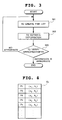
- Fig. 3 is a flow chart for use in explaining processing conducted by the deformation estimating unit 11 of the present embodiment.
- a graphic form to be examined which is a graphic form as an object of examination and a model graphic form as a graphic form based on which comparison is made are applied to the graphic form to be examined input unit 20 and the model graphic form input unit 30, respectively (Step 201).
- Employed as the method of inputting the respective graphic forms are, for example, that of inputting information of a feature point indicative of features of each graphic form which is extracted in advance and that of inputting image data of each graphic form and extracting information of its feature point on the side of the graphic form to be examined input unit 20 and the model graphic form input unit 30 to output extracted information to the data processing unit 10.
- a method can be adopted of inputting image data of a character to be identified to the graphic form to be examined input unit 20 and inputting character data registered in a dictionary to the model graphic form input unit 30.
- image data of a fingerprint whose owner is to be found can be input to the graphic form to be examined input unit 20 and fingerprint data registered in a fingerprint data base can be input to the model graphic form input unit 30.
- the graphic form to be examined input unit 20 may receive input of feature point information of a graphic form to be examined which is extracted in advance or may receive input of a graphic form to be examined itself and extract information of a feature point at the graphic form to be examined input unit 20.
- the model graphic input unit 30 may receive input of feature point information of a model graphic form which is extracted in advance or may receive input of a model graphic form itself and extract information of a feature point at the model graphic form input unit 30.
- a point at which a line ceases a point at which a line ceases (end point)
- a point at which a line branches branch point
- a point at which lines intersect with each other intersection point
- a feature quantity which is data indicative of a degree of features at each feature point such data as a position of a feature point and a direction of a line which touches a feature point can be used.
- values of a curvature of a line which touches a point and a curvature of a line adjacent to the same or information such as location of surrounding feature points and the number of lines crossing between surrounding feature points may be added.
- the data of each graphic form applied to the graphic form to be examined input unit 20 and the model graphic form input unit 30 is transferred to the deformation estimating unit 11 of the data processing unit 10.
- the deformation estimating unit 11 compares feature point information of the graphic form to be examined which is input through the graphic form to be examined input unit 20 and feature point information of the model graphic form input through the model graphic form input unit 30 to estimate deformation generated in the graphic form to be examined (Step 202).
- the deformation estimating unit 11 selects a pair of feature points which can be considered to be the same feature point in the two graphic forms and based on a difference in position between these feature points in the two graphic forms, estimates deformation generated in the graphic form to be examined.
- deformation generated in a graphic form in a case of comparison for character recognition between a character registered in a dictionary and a character input by a camera or the like, for example, an image of a character shot by a camera or the like which is input to the graphic form to be examined input unit 20 will be optically distorted at the time of input.
- fingerprint recognition in a case where data of a fingerprint whose owner is to be found is input to the graphic form to be examined input unit 20 and fingerprint data registered at a fingerprint data base is input to the model graphic input unit 30, a graphic form to be examined and a model graphic form are both deformed at the time of fingerprinting
- the deformation correcting unit 12 corrects the deformation of the graphic form to be examined by subjecting the graphic form to be examined to deformation having a reverse relationship with the deformation estimated by the deformation estimating unit 11 (Step 203).
- the similarity determining unit 13 compares the graphic form to be examined which is obtained with its deformation corrected by the deformation correcting unit 12 and the model graphic form to calculate similarity between the two graphic forms (Step 204).
- the output unit 40 outputs the similarity calculated at the similarity determining unit 13 (Step 205).
- Step 203 other than a method of subjecting the graphic form to be examined to deformation in reverse relationship with the deformation estimated at the deformation estimating unit 11, thereby correcting the deformation of the graphic form to be examined, a method can be adopted of subjecting the model graphic form to the deformation estimated at the deformation estimating unit 11, thereby matching deformation of the model graphic form and that of the graphic form to be examined with each other.
- This method enables comparison of the two graphic forms to calculate similarity between the two graphic forms at Step 204 in the same manner as described above.
- Step 301 compare feature point information of the graphic form to be examined which is applied through the graphic form to be examined input unit 20 and feature point information of the model graphic form which is applied through the model graphic form input unit 30 and sequentially register a pair of feature points determined to be corresponding feature points as a feature point pair for deformation estimation to create a list of feature point pairs for deformation estimation (Step 301).
- Step 301 for example, select one arbitrary feature point "a” from among feature points of the graphic form to be examined and one arbitrary feature point "b” from among feature points of the model graphic form to obtain a difference between a feature quantity of the feature point "a” and that of the feature point “b” and when the difference between these feature quantities is not greater than a predetermined threshold value, determine that they are corresponding feature points to register the pair of the feature points, the feature point "a” of the graphic form to be examined and the feature point "b” of the model graphic form which are determined to be corresponding feature points, at the list of feature point pairs for deformation estimation.
- Step 302 estimate deformation which best matches feature points as a pair registered in the list of feature point pairs for deformation estimation.
- Step 303 verify the estimated deformation and when the deformation is appropriate, output the deformation.
- the deformation model for use can be changed to try again to create a list of feature point pairs for deformation estimation.
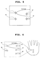
- a position of a feature point in the model graphic form and a position of a feature point in the graphic form to be examined in an i-th pair pi are (xi, yi) and (Xi, Yi), respectively.
- the feature point at (xi, yi) on the model graphic form will shift to the position shown by the expression in Fig. 6.
- the deformation generated in the graphic form to be examined can be estimated as that expressed by the Mathematical Expression 5 (Step 302). Result of overlap between the model graphic form subjected to the estimated deformation and the graphic form to be examined is as shown in Fig. 9.
- the vector b in the Mathematical Expression 5 represents parallel displacement and the matrix A represents contraction/expansion, rotation and shearing.
- the elastic energy F will be expressed as shown in the Mathematical Expression 9 (in the Mathematical Expression 9, K represents a surrounding compression rate and ⁇ represents a shearing rate, both of which are constants determined by their materials).
- ⁇ 0 is a parameter corresponding to contraction/expansion (which takes "0" when neither contraction nor expansion is generated, takes a negative value when contraction is generated and takes a positive value when expansion is generated), while ⁇ 1 and ⁇ 2 are parameters corresponding to shearing distortion (which takes "0" when no distortion is generated and takes a larger absolute value as distortion is enhanced).
- a graphic form as an object of examination is a fingerprint, a palmprint or the like
- contraction/expansion is limited. Therefore, when ⁇ 0 exceeds a range of possible contraction/expansion which is predetermined for a finger, abandon the estimation.
- distortion of a fingerprint, a palmprint and the like is also limited, when ⁇ 1 or ⁇ 2 exceeds a possible range of distortion for a fingerprint or a palmprint, abandon the estimation as well.
- elastic energy itself when it fails to fall within an assumed range for a fingerprint or a palmprint, abandon the estimation.
- Possible processing to be conducted subsequently when estimation is abandoned are processing of changing a deformation model, processing of executing estimation of deformation again after changing a method of creating a list of feature point pairs for deformation estimation and other processing.
- a finger is a rigid body on which severer constrain is placed than that on an elastic body
- consideration will be given to a deformation model of the rigid body (because a rigid body will not be deformed, the model includes only the parameters of parallel displacement and rotation).
- the model is a rigid body
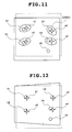
- FIG. 12 is a diagram showing the graphic forms subjected to elastic deformation estimated using the modified list of feature point pairs for deformation estimation including p1:(a1, b1), p3:(a3, b2), p4: (a4, b4) and p6:(a2, b3).
- the deformation Upon estimation of deformation, by subjecting the feature point (X, Y) of the graphic form to be examined to inversion of the formula of the Mathematical Expression 5 which inversion is represented by the formula of the Mathematical Expression 10, the deformation will be corrected to convert the feature point to coordinates (x, y) of a feature point which can be directly compared with the model graphic form, so that by the comparison between the graphic form to be examined whose deformation has been corrected and the model graphic form, similarity between the graphic form to be examined and the model graphic form is calculated to determine whether the graphic form to be examined and the model graphic form are the same graphic form or not.
- deformation generated in a graphic form to be examined is estimated to correct the deformation and the graphic form to be examined whose deformation has been corrected and the model graphic form are compared to collate the two graphic forms, even when the graphic form to be examined has deformation (or when deformation of the graphic form to be examined is different from that of the model graphic form), the graphic form to be examined and the model graphic form can be strictly discriminated and collated with each other.
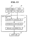
- Fig. 13 is a block diagram showing a structure of a pattern collation device according to the present embodiment
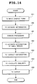
- Fig. 14 is a flow chart for use in explaining processing of pattern collation according to the present embodiment.
- the present embodiment differs from the first embodiment in the function of a deformation estimating unit 11a in a data processing unit 10a
- Pattern collation processing of the present embodiment is the same as that of the first embodiment with the only difference being that new Steps 401 and 402 are added after Step 202.
- Step 202 the same processing as the deformation estimating processing of the first embodiment is executed to estimate deformation generated in the graphic form to be examined as a whole (Step 202).
- Step 401 divide the graphic form into predetermined small regions (Step 401) and conduct deformation estimation processing on a region basis in the same manner as that of Step 202 to estimate deformation at each region (Step 402).
- the small region in a case where based on the deformation estimation result of each small region, the small region can not be assumed to singly have peculiar deformation in consideration of nature of an object of examination (as in Step 303 of the first embodiment), appropriateness of the estimation may be verified. It is for example possible, after estimating deformation of each small region, to evaluate appropriateness of the estimation by evaluating a relationship with deformation estimated with respect to a nearby region or a relationship with deformation estimated with respect to the whole region and when inappropriate deformation is being estimated, try estimation again.
- Steps 401 and 402 of the present embodiment enable estimation of deformation of each part.
- the present embodiment has an effect of coping with a graphic form whose deformation manner differs in each part, thereby reducing a possibility of erroneous estimation of deformation.
- Fig. 15 is a block diagram showing a structure of a pattern collation device according to the present embodiment
- Fig. 16 is a flow chart for use in explaining processing of pattern collation according to the present embodiment.
- the present embodiment differs from the first embodiment in the function of a deformation estimating unit 11b in a data processing unit 10b
- Pattern collation processing of the present embodiment is the same as that of the first embodiment with the only difference being that Steps 601, 602 and 603 are newly added to Step 202.
- Step 202 executes the same processing as the deformation estimating processing of the first embodiment to estimate deformation generated in the graphic form to be examined as a whole (Step 202).
- Step 601 measure a degree of concentration of feature points in the vicinity of an arbitrary feature point.
- this is the processing of, with a region of a predetermined size around a noted arbitrary feature point set to be a vicinity of the noted feature point, measuring a degree of concentration of feature points in the vicinity of the point.
- Step 602 when there exist feature point pairs as many as or more than the number of a predetermined threshold value (Step 602), by applying the same deformation estimating processing as that of Step 202 to the vicinity, estimate deformation in the vicinity of the feature point from nearby feature point pairs (Step 603).
- the present embodiment copes with a graphic form whose deformation manner varies with each part, thereby reducing a possibility of erroneous deformation estimation.
- Step 602 when feature point pairs fail to exist as many as or more than the number of the predetermined threshold value in the vicinity of feature point (Step 602), no processing of estimating deformation in the vicinity is necessary and deformation estimated for the graphic form to be examined as a whole at Step 202 is used.
- Step 203 deform the graphic form to be examined (or model graphic form) (Step 203) to calculate similarity between the two graphic forms (Step 204).
- deformation is estimated at each feature point to evaluate a relationship with deformation estimated in the vicinity of the feature point or a relationship with deformation estimated as a whole, thereby evaluating appropriateness of the estimation (as is done at Step 303 of the first embodiment) and when inappropriate deformation is estimated, the estimation can be tried again.
- the present invention has an effect of coping with a graphic form whose deformation manner varies with each part, thereby reducing a possibility of erroneous deformation estimation.
- the functions of the data processing units 10, 10a and 10b, the deformation estimating unit 11, the deformation estimating unit 11a, the deformation estimating unit 11b, the deformation correcting unit 12, the similarity determining unit 13 and the like and other functions can be realized not only by hardware but also by loading a pattern collation program which is a computer program having the respective functions into a memory of a computer processing device.
- Fig. 18 is a diagram showing one embodiment of a structure having a recording medium in which a pattern collation program is recorded according to the present invention.
- the pattern collation program is stored in a recording medium 90 such as a magnetic disc or a semiconductor memory. Then, loading the program into a data processing unit 10c which is a computer processing device from the recording medium to control operation of the data processing unit 10c realizes the above-described functions. As a result, the data processing unit 10c executes the processing conducted by the data processing units 10, 10a and 10b in the first, second and third embodiments under the control of the pattern collation program.
- a recording medium 90 such as a magnetic disc or a semiconductor memory.
- the pattern collation device of the present invention attains the following effects.
- the present invention since deformation generated in a graphic form to be examined is estimated and corrected, the graphic form to the examined can be correctly identified even when the form is deformed. Moreover, the present invention enables a change of a feature quantity caused by deformation and an error of extraction of a feature quantity to be separated to realize accurate comparison of feature quantities.
- the graphic form to be examined can be correctly discriminated even when the form partly has different deformation.
- the third embodiment of the present invention when the number of nearby feature point pairs existing in a graphic form to be examined is more than a predetermined number, deformation around the feature points is estimated to reduce deformation estimation errors, so that even when the graphic form to be examined partly has different deformation, it can be discriminated correctly.
Landscapes
- Engineering & Computer Science (AREA)
- Theoretical Computer Science (AREA)
- Computer Vision & Pattern Recognition (AREA)
- Multimedia (AREA)
- General Physics & Mathematics (AREA)
- Physics & Mathematics (AREA)
- Computing Systems (AREA)
- General Health & Medical Sciences (AREA)
- Medical Informatics (AREA)
- Software Systems (AREA)
- Evolutionary Computation (AREA)
- Databases & Information Systems (AREA)
- Artificial Intelligence (AREA)
- Health & Medical Sciences (AREA)
- Collating Specific Patterns (AREA)
- Image Analysis (AREA)
Priority Applications (1)
| Application Number | Priority Date | Filing Date | Title |
|---|---|---|---|
| EP07020623A EP1881444B1 (de) | 2001-03-29 | 2002-03-28 | Gerät, Verfahren und Programm zum Vergleichen von Mustern |
Applications Claiming Priority (2)
| Application Number | Priority Date | Filing Date | Title |
|---|---|---|---|
| JP2001096223 | 2001-03-29 | ||
| JP2001096223A JP2002298141A (ja) | 2001-03-29 | 2001-03-29 | パターン照合装置とそのパターン照合方法、及びパターン照合プログラム |
Related Child Applications (2)
| Application Number | Title | Priority Date | Filing Date |
|---|---|---|---|
| EP07020623A Division EP1881444B1 (de) | 2001-03-29 | 2002-03-28 | Gerät, Verfahren und Programm zum Vergleichen von Mustern |
| EP07020623.0 Division-Into | 2007-10-22 |
Publications (3)
| Publication Number | Publication Date |
|---|---|
| EP1248226A2 true EP1248226A2 (de) | 2002-10-09 |
| EP1248226A3 EP1248226A3 (de) | 2005-10-12 |
| EP1248226B1 EP1248226B1 (de) | 2011-11-23 |
Family
ID=18950165
Family Applications (2)
| Application Number | Title | Priority Date | Filing Date |
|---|---|---|---|
| EP02007179A Expired - Lifetime EP1248226B1 (de) | 2001-03-29 | 2002-03-28 | Gerät, Verfahren und Programm zum Vergleichen von Mustern |
| EP07020623A Expired - Lifetime EP1881444B1 (de) | 2001-03-29 | 2002-03-28 | Gerät, Verfahren und Programm zum Vergleichen von Mustern |
Family Applications After (1)
| Application Number | Title | Priority Date | Filing Date |
|---|---|---|---|
| EP07020623A Expired - Lifetime EP1881444B1 (de) | 2001-03-29 | 2002-03-28 | Gerät, Verfahren und Programm zum Vergleichen von Mustern |
Country Status (8)
| Country | Link |
|---|---|
| US (1) | US7027624B2 (de) |
| EP (2) | EP1248226B1 (de) |
| JP (1) | JP2002298141A (de) |
| KR (1) | KR100479777B1 (de) |
| CN (1) | CN1276389C (de) |
| AU (1) | AU785140B2 (de) |
| CA (1) | CA2379452C (de) |
| DE (1) | DE60239971D1 (de) |
Cited By (1)
| Publication number | Priority date | Publication date | Assignee | Title |
|---|---|---|---|---|
| EP2105864A3 (de) * | 2008-03-27 | 2010-11-10 | Fujitsu Limited | Authentifizierungsvorrichtung und Authentifizierungsverfahren |
Families Citing this family (28)
| Publication number | Priority date | Publication date | Assignee | Title |
|---|---|---|---|---|
| JP3842080B2 (ja) * | 2001-07-06 | 2006-11-08 | グローリー工業株式会社 | 署名照合装置、署名照合方法および署名照合プログラム |
| US7466846B2 (en) | 2002-09-25 | 2008-12-16 | The Hong Kong Polytechnic University | Method for analyzing a palm print for the identification of an individual using gabor analysis |
| US7496214B2 (en) | 2002-09-25 | 2009-02-24 | The Hong Kong Polytechnic University | Method of palm print identification |
| WO2005045358A2 (en) * | 2003-11-05 | 2005-05-19 | Francos Joseph M | Parametric estimation of multi-dimensional homeomorphic transformations |
| US8275204B1 (en) | 2003-11-05 | 2012-09-25 | Shahar Kovalsky | Estimation of joint radiometric and geometric image deformations |
| FR2862785B1 (fr) * | 2003-11-21 | 2006-01-20 | Atmel Grenoble Sa | Capteur d'empreinte digitale a deux sens de balayage |
| JP4267475B2 (ja) * | 2004-02-13 | 2009-05-27 | 富士通株式会社 | 図面照合装置 |
| JPWO2005088542A1 (ja) * | 2004-03-17 | 2008-01-31 | 松下電器産業株式会社 | 食材調理操作認識システム及び食材調理操作認識プログラム |
| JP4605445B2 (ja) * | 2004-08-24 | 2011-01-05 | ソニー株式会社 | 画像処理装置および方法、記録媒体、並びにプログラム |
| US8437502B1 (en) * | 2004-09-25 | 2013-05-07 | Cognex Technology And Investment Corporation | General pose refinement and tracking tool |
| US20060088225A1 (en) | 2004-10-26 | 2006-04-27 | The Secretary Of State For The Home Department | Comparison |
| WO2006131848A2 (en) * | 2005-06-08 | 2006-12-14 | Koninklijke Philips Electronics N.V. | Point subselection for fast deformable point-based imaging |
| CN100464346C (zh) * | 2006-04-29 | 2009-02-25 | 北大方正集团有限公司 | 一种表格图像几何畸变的数字校正方法 |
| KR20080110242A (ko) | 2007-06-15 | 2008-12-18 | 한국외국어대학교 연구산학협력단 | 지문 정합 시스템 및 방법 |
| US8340370B2 (en) | 2008-02-19 | 2012-12-25 | Nec Corporation | Pattern verification apparatus, pattern verification method, and program |
| GB0819069D0 (en) | 2008-10-17 | 2008-11-26 | Forensic Science Service Ltd | Improvements in and relating to methods and apparatus for comparison |
| JP5563231B2 (ja) * | 2009-03-25 | 2014-07-30 | 日本電気株式会社 | 縞模様画像鑑定装置、縞模様画像鑑定方法及びプログラム |
| JP5717055B2 (ja) * | 2010-01-08 | 2015-05-13 | 日本電気株式会社 | 類似度算出装置、類似度算出方法、及びプログラム |
| WO2012063708A1 (ja) * | 2010-11-08 | 2012-05-18 | 日本電気株式会社 | 画像照合装置 |
| CN102200999B (zh) * | 2011-04-27 | 2012-10-10 | 华中科技大学 | 一种检索相似性形状的方法 |
| CN102324096B (zh) * | 2011-07-19 | 2014-07-02 | 国家电网公司 | 特征点校正分区拼接方法及装置 |
| CN102306382A (zh) * | 2011-06-28 | 2012-01-04 | 吉林大学 | 基于道路环境固有特征的事故现场图像校正方法 |
| CN103733225B (zh) | 2011-08-16 | 2016-08-17 | 日本电气株式会社 | 特征点对等系统、特征点对等方法、以及记录介质 |
| JP2015087941A (ja) * | 2013-10-30 | 2015-05-07 | オリンパス株式会社 | 特徴点マッチング処理装置、特徴点マッチング処理方法、およびプログラム |
| JP6593327B2 (ja) * | 2014-05-07 | 2019-10-23 | 日本電気株式会社 | 画像処理装置、画像処理方法およびコンピュータ可読記録媒体 |
| CN103984929B (zh) * | 2014-05-20 | 2017-04-19 | 清华大学 | 扭曲指纹的校正方法及系统 |
| CN109005387B (zh) * | 2018-08-08 | 2021-04-02 | 盎锐(上海)信息科技有限公司 | 用于生产线中的影像获取装置及数据分析方法 |
| CN112233313B (zh) * | 2020-10-19 | 2022-06-21 | 中国工商银行股份有限公司 | 一种纸币识别方法、装置及设备 |
Family Cites Families (20)
| Publication number | Priority date | Publication date | Assignee | Title |
|---|---|---|---|---|
| US4641350A (en) * | 1984-05-17 | 1987-02-03 | Bunn Robert F | Fingerprint identification system |
| KR880700362A (ko) | 1985-04-02 | 1988-02-22 | 쉴러 마이클 | 정합장치 및 방법 |
| JPH02187885A (ja) | 1989-01-13 | 1990-07-24 | Canon Inc | 文字認識装置 |
| JP2929802B2 (ja) | 1991-09-20 | 1999-08-03 | 株式会社デンソー | 指紋照合システム |
| JP3183949B2 (ja) | 1992-06-22 | 2001-07-09 | 株式会社リコー | パターン認識処理方法 |
| JPH0830783A (ja) | 1994-07-12 | 1996-02-02 | Meidensha Corp | 2次元物体の認識方法 |
| JPH08147411A (ja) | 1994-11-21 | 1996-06-07 | Oki Electric Ind Co Ltd | 文字認識装置 |
| JPH08249422A (ja) * | 1995-03-08 | 1996-09-27 | Canon Inc | 文字処理装置及び方法 |
| US5892838A (en) | 1996-06-11 | 1999-04-06 | Minnesota Mining And Manufacturing Company | Biometric recognition using a classification neural network |
| US5909501A (en) * | 1996-09-09 | 1999-06-01 | Arete Associates | Systems and methods with identity verification by comparison and interpretation of skin patterns such as fingerprints |
| JP3625245B2 (ja) | 1996-10-16 | 2005-03-02 | 株式会社リコー | 画像処理方法及び画像処理装置 |
| JP2878656B2 (ja) | 1996-10-02 | 1999-04-05 | 良吉 玉置 | 印鑑照合方法及び装置 |
| JPH10124684A (ja) | 1996-10-16 | 1998-05-15 | Ricoh Co Ltd | 画像処理方法,記憶媒体及び画像処理装置 |
| US5883971A (en) * | 1996-10-23 | 1999-03-16 | International Business Machines Corporation | System and method for determining if a fingerprint image contains an image portion representing a smudged fingerprint impression |
| JP2944557B2 (ja) | 1997-02-27 | 1999-09-06 | 日本電気ソフトウェア株式会社 | 縞パターン照合装置 |
| JP3002721B2 (ja) | 1997-03-17 | 2000-01-24 | 警察庁長官 | 図形位置検出方法及びその装置並びにプログラムを記録した機械読み取り可能な記録媒体 |
| US6049621A (en) * | 1997-08-22 | 2000-04-11 | International Business Machines Corporation | Determining a point correspondence between two points in two respective (fingerprint) images |
| US6466686B2 (en) * | 1998-01-07 | 2002-10-15 | International Business Machines Corporation | System and method for transforming fingerprints to improve recognition |
| JP3630569B2 (ja) | 1998-10-23 | 2005-03-16 | 株式会社東芝 | 映像領域追跡方法および装置 |
| KR100299858B1 (ko) * | 1999-03-19 | 2001-09-26 | 이영익 | 지문 매칭 방법 |
-
2001
- 2001-03-29 JP JP2001096223A patent/JP2002298141A/ja active Pending
-
2002
- 2002-03-27 AU AU27741/02A patent/AU785140B2/en not_active Ceased
- 2002-03-27 US US10/106,444 patent/US7027624B2/en not_active Expired - Lifetime
- 2002-03-28 DE DE60239971T patent/DE60239971D1/de not_active Expired - Lifetime
- 2002-03-28 CA CA002379452A patent/CA2379452C/en not_active Expired - Fee Related
- 2002-03-28 EP EP02007179A patent/EP1248226B1/de not_active Expired - Lifetime
- 2002-03-28 EP EP07020623A patent/EP1881444B1/de not_active Expired - Lifetime
- 2002-03-29 KR KR10-2002-0017391A patent/KR100479777B1/ko not_active Expired - Fee Related
- 2002-03-29 CN CNB021084149A patent/CN1276389C/zh not_active Expired - Fee Related
Non-Patent Citations (2)
| Title |
|---|
| ANDRES ALMANSA; LAURENT COHEN: "Fingerprint image matching by minimization of a thin-plate energy using a two-step algorithm with auxiliary variables", IEEE, 2000 |
| HAILI CHUI; ANAND RANGARAJAN: "A New Algorithm for Non-Rigid Point Matching", IEEE, 2000 |
Cited By (2)
| Publication number | Priority date | Publication date | Assignee | Title |
|---|---|---|---|---|
| EP2105864A3 (de) * | 2008-03-27 | 2010-11-10 | Fujitsu Limited | Authentifizierungsvorrichtung und Authentifizierungsverfahren |
| US8520914B2 (en) | 2008-03-27 | 2013-08-27 | Fujitsu Limited | Authentication apparatus and authentication method |
Also Published As
| Publication number | Publication date |
|---|---|
| US20020181782A1 (en) | 2002-12-05 |
| JP2002298141A (ja) | 2002-10-11 |
| KR100479777B1 (ko) | 2005-03-30 |
| CN1379364A (zh) | 2002-11-13 |
| EP1881444B1 (de) | 2011-05-04 |
| EP1881444A1 (de) | 2008-01-23 |
| AU2774102A (en) | 2002-10-03 |
| KR20020077257A (ko) | 2002-10-11 |
| CN1276389C (zh) | 2006-09-20 |
| US7027624B2 (en) | 2006-04-11 |
| AU785140B2 (en) | 2006-10-05 |
| EP1248226A3 (de) | 2005-10-12 |
| EP1248226B1 (de) | 2011-11-23 |
| DE60239971D1 (de) | 2011-06-16 |
| CA2379452C (en) | 2006-09-19 |
| CA2379452A1 (en) | 2002-09-29 |
Similar Documents
| Publication | Publication Date | Title |
|---|---|---|
| EP1248226A2 (de) | Gerät, Verfahren und Programm zum Vergleichen von Mustern | |
| EP2107507B1 (de) | Musterausrichtungsverfahren, Verifizierungsverfahren und Verifizierungsvorrichtung | |
| JP2737734B2 (ja) | 指紋分類装置 | |
| US7031501B2 (en) | Image collation method and apparatus and recording medium storing image collation program | |
| AU722613B2 (en) | Fingerprint characteristic extraction apparatus as well as fingerprint classification apparatus and fingerprint verification apparatus for use with fingerprint characteristic extraction apparatus | |
| EP3057037A1 (de) | Vorrichtung und verfahren zur registrierung biometrischer informationen | |
| WO2008054940A2 (en) | Print matching method and apparatus using pseudo-ridges | |
| US20100183230A1 (en) | Feature attribute calculation apparatus, feature extraction apparatus, pattern matching apparatus, and method | |
| KR101959892B1 (ko) | 지문 인증 방법 및 장치 | |
| JP3709803B2 (ja) | パターン照合装置とそのパターン照合方法、及びパターン照合プログラム | |
| US6430308B1 (en) | Handwriting verification device | |
| US20060120578A1 (en) | Minutiae matching | |
| KR101649547B1 (ko) | 점 매칭을 이용한 땀구멍 지도 인식 및 분석 방법과 그 장치 | |
| JP2866461B2 (ja) | 指紋照合装置 | |
| KR100837002B1 (ko) | 패턴 식별 시스템, 패턴 식별 방법, 및 패턴 식별 프로그램을 기록한 기록매체 | |
| CN118172803A (zh) | 一种掌纹识别方法和装置 | |
| JP4304722B2 (ja) | 変形推定方法、変形推定装置及び変形推定プログラム | |
| JPH01271884A (ja) | 指紋中心検出装置 | |
| KR100629302B1 (ko) | 지문등록을 위한 지문템플릿 생성방법 | |
| US20080240522A1 (en) | Fingerprint Authentication Method Involving Movement of Control Points | |
| JP2002083300A (ja) | 照合登録画像選択方法および画像照合装置 | |
| KR20230063216A (ko) | 딥러닝 기반 필적 인식 장치 및 방법 | |
| JPH1131195A (ja) | 文字認識装置、文字認識方法、及び、記憶媒体 | |
| Hsiao et al. | Incrementally verifying automata for fingerprint sensors | |
| KR20090104647A (ko) | 패턴의 정렬 방법, 대조 방법 및 대조 장치 |
Legal Events
| Date | Code | Title | Description |
|---|---|---|---|
| PUAI | Public reference made under article 153(3) epc to a published international application that has entered the european phase |
Free format text: ORIGINAL CODE: 0009012 |
|
| AK | Designated contracting states |
Kind code of ref document: A2 Designated state(s): AT BE CH CY DE DK ES FI FR GB GR IE IT LI LU MC NL PT SE TR |
|
| AX | Request for extension of the european patent |
Free format text: AL;LT;LV;MK;RO;SI |
|
| PUAL | Search report despatched |
Free format text: ORIGINAL CODE: 0009013 |
|
| AK | Designated contracting states |
Kind code of ref document: A3 Designated state(s): AT BE CH CY DE DK ES FI FR GB GR IE IT LI LU MC NL PT SE TR |
|
| AX | Request for extension of the european patent |
Extension state: AL LT LV MK RO SI |
|
| 17P | Request for examination filed |
Effective date: 20050907 |
|
| AKX | Designation fees paid |
Designated state(s): DE FR GB IT NL SE |
|
| 17Q | First examination report despatched |
Effective date: 20051220 |
|
| 17Q | First examination report despatched |
Effective date: 20051220 |
|
| GRAP | Despatch of communication of intention to grant a patent |
Free format text: ORIGINAL CODE: EPIDOSNIGR1 |
|
| GRAS | Grant fee paid |
Free format text: ORIGINAL CODE: EPIDOSNIGR3 |
|
| GRAA | (expected) grant |
Free format text: ORIGINAL CODE: 0009210 |
|
| AK | Designated contracting states |
Kind code of ref document: B1 Designated state(s): DE FR GB IT NL SE |
|
| REG | Reference to a national code |
Ref country code: GB Ref legal event code: FG4D |
|
| REG | Reference to a national code |
Ref country code: NL Ref legal event code: T3 |
|
| REG | Reference to a national code |
Ref country code: DE Ref legal event code: R096 Ref document number: 60241596 Country of ref document: DE Effective date: 20120126 |
|
| REG | Reference to a national code |
Ref country code: SE Ref legal event code: TRGR |
|
| PGFP | Annual fee paid to national office [announced via postgrant information from national office to epo] |
Ref country code: IT Payment date: 20120328 Year of fee payment: 11 |
|
| PLBE | No opposition filed within time limit |
Free format text: ORIGINAL CODE: 0009261 |
|
| STAA | Information on the status of an ep patent application or granted ep patent |
Free format text: STATUS: NO OPPOSITION FILED WITHIN TIME LIMIT |
|
| 26N | No opposition filed |
Effective date: 20120824 |
|
| REG | Reference to a national code |
Ref country code: DE Ref legal event code: R097 Ref document number: 60241596 Country of ref document: DE Effective date: 20120824 |
|
| PGFP | Annual fee paid to national office [announced via postgrant information from national office to epo] |
Ref country code: DE Payment date: 20130320 Year of fee payment: 12 Ref country code: FR Payment date: 20130325 Year of fee payment: 12 Ref country code: SE Payment date: 20130312 Year of fee payment: 12 Ref country code: GB Payment date: 20130327 Year of fee payment: 12 |
|
| PGFP | Annual fee paid to national office [announced via postgrant information from national office to epo] |
Ref country code: NL Payment date: 20130316 Year of fee payment: 12 |
|
| REG | Reference to a national code |
Ref country code: DE Ref legal event code: R119 Ref document number: 60241596 Country of ref document: DE |
|
| REG | Reference to a national code |
Ref country code: NL Ref legal event code: V1 Effective date: 20141001 |
|
| REG | Reference to a national code |
Ref country code: SE Ref legal event code: EUG |
|
| GBPC | Gb: european patent ceased through non-payment of renewal fee |
Effective date: 20140328 |
|
| PG25 | Lapsed in a contracting state [announced via postgrant information from national office to epo] |
Ref country code: SE Free format text: LAPSE BECAUSE OF NON-PAYMENT OF DUE FEES Effective date: 20140329 |
|
| REG | Reference to a national code |
Ref country code: FR Ref legal event code: ST Effective date: 20141128 |
|
| REG | Reference to a national code |
Ref country code: DE Ref legal event code: R119 Ref document number: 60241596 Country of ref document: DE Effective date: 20141001 |
|
| PG25 | Lapsed in a contracting state [announced via postgrant information from national office to epo] |
Ref country code: DE Free format text: LAPSE BECAUSE OF NON-PAYMENT OF DUE FEES Effective date: 20141001 Ref country code: FR Free format text: LAPSE BECAUSE OF NON-PAYMENT OF DUE FEES Effective date: 20140331 Ref country code: GB Free format text: LAPSE BECAUSE OF NON-PAYMENT OF DUE FEES Effective date: 20140328 |
|
| PG25 | Lapsed in a contracting state [announced via postgrant information from national office to epo] |
Ref country code: NL Free format text: LAPSE BECAUSE OF NON-PAYMENT OF DUE FEES Effective date: 20141001 |
|
| PG25 | Lapsed in a contracting state [announced via postgrant information from national office to epo] |
Ref country code: IT Free format text: LAPSE BECAUSE OF NON-PAYMENT OF DUE FEES Effective date: 20140328 |