EP1248278A1 - Déclencheur électromagnétique comportant un circuit électromagnétique dont l'armature mobile est apte à accuper trois positions d'équilibre stable - Google Patents
Déclencheur électromagnétique comportant un circuit électromagnétique dont l'armature mobile est apte à accuper trois positions d'équilibre stable Download PDFInfo
- Publication number
- EP1248278A1 EP1248278A1 EP02290799A EP02290799A EP1248278A1 EP 1248278 A1 EP1248278 A1 EP 1248278A1 EP 02290799 A EP02290799 A EP 02290799A EP 02290799 A EP02290799 A EP 02290799A EP 1248278 A1 EP1248278 A1 EP 1248278A1
- Authority
- EP
- European Patent Office
- Prior art keywords
- armature
- trip device
- electromagnetic
- electromagnetic trip
- fixed
- Prior art date
- Legal status (The legal status is an assumption and is not a legal conclusion. Google has not performed a legal analysis and makes no representation as to the accuracy of the status listed.)
- Granted
Links
Images



Classifications
-
- H—ELECTRICITY
- H01—ELECTRIC ELEMENTS
- H01H—ELECTRIC SWITCHES; RELAYS; SELECTORS; EMERGENCY PROTECTIVE DEVICES
- H01H71/00—Details of the protective switches or relays covered by groups H01H73/00 - H01H83/00
- H01H71/10—Operating or release mechanisms
- H01H71/12—Automatic release mechanisms with or without manual release
- H01H71/24—Electromagnetic mechanisms
- H01H71/32—Electromagnetic mechanisms having permanently magnetised part
- H01H71/327—Manufacturing or calibrating methods, e.g. air gap treatments
-
- H—ELECTRICITY
- H01—ELECTRIC ELEMENTS
- H01H—ELECTRIC SWITCHES; RELAYS; SELECTORS; EMERGENCY PROTECTIVE DEVICES
- H01H50/00—Details of electromagnetic relays
- H01H50/16—Magnetic circuit arrangements
- H01H50/163—Details concerning air-gaps, e.g. anti-remanence, damping, anti-corrosion
-
- H—ELECTRICITY
- H01—ELECTRIC ELEMENTS
- H01H—ELECTRIC SWITCHES; RELAYS; SELECTORS; EMERGENCY PROTECTIVE DEVICES
- H01H71/00—Details of the protective switches or relays covered by groups H01H73/00 - H01H83/00
- H01H71/10—Operating or release mechanisms
- H01H71/12—Automatic release mechanisms with or without manual release
- H01H71/24—Electromagnetic mechanisms
- H01H71/32—Electromagnetic mechanisms having permanently magnetised part
- H01H71/321—Electromagnetic mechanisms having permanently magnetised part characterised by the magnetic circuit or active magnetic elements
- H01H71/323—Electromagnetic mechanisms having permanently magnetised part characterised by the magnetic circuit or active magnetic elements with rotatable armature
Definitions
- the invention relates to an electromagnetic trip device comprising a electromagnetic circuit comprising a fixed armature as well as an armature mobile capable of occupying two positions of stable equilibrium, namely a working position in which it is pressed against the fixed frame and closes the electromagnetic circuit, and a rest position in which it is away from the fixed armature and opens the electromagnetic circuit.
- An electromagnetic trip device of this type is known from the document FR-A-2 620 264.
- This type of trigger has a number of drawbacks, among which difficult access to the air gap between the reinforcements once these assemblies. However, there may remain undesirable dust which is likely to modify the air gap and, therefore, affect the proper functioning of the trigger.
- the invention aims to solve in particular the aforementioned drawbacks in providing a simple design electromagnetic trip unit which reliable, precise and durable operation.
- the invention provides an electromagnetic trigger such as mentioned in the introduction, characterized in that the movable frame is suitable for occupy a third stable equilibrium position in which it is spread of the fixed frame beyond the rest position.
- the air gap is thus definitively free of all dust undesirable and it remains constant in a lasting manner.
- the movable armature is thus positioned stably and precise, and at the same time easily reversible, in its third position.
- an electromagnetic trip device 1 to high sensitivity for a switch or circuit breaker which includes, in a case 2 assumed to be fixed, composed of a base 3 capped with a cover 4, a circuit electromagnetic 5 comprising a fixed frame 6 in the shape of a U, secured the housing 2 and a movable frame 7 called a pallet, capable of rotate to open or close the electromagnetic circuit 5.
- trigger 1 is described with reference to this mark, according to the orientation adopted in FIG. 2, which corresponds to the usual use most common of trigger 1.
- the fixed frame 6 and the pallet 7 are both produced in a ferromagnetic material, such as an Iron - Nickel alloy.
- the fixed frame 6 comprises a first branch 8 called front and a second branch 9 called rear, connected by a base 10 resting on the base 3 case 2.
- the electromagnetic circuit 5 comprises a coil 11 comprising a carcass 12 on which a coil 13 is wound, the carcass 12 being threaded on the front branch 8 of the fixed frame 6 and secured to the base 3.
- the magnet 14 for the magnetic polarization of the fixed armature 6.
- the magnet 14, shaped parallelepiped, is fixed by one of its ends on the base 10 of the fixed armature 6, preferably by welding. More specifically, the magnet 14 is fixed on an upper face 15 of the base 10, which also has a face lower 16 opposite.
- Pallet 7 is likely to occupy at least two equilibrium positions stable, i.e. a working or engaged position, in which it found pressed against the branches 8, 9 of the fixed armature 6 and closes the circuit electromagnetic 5, and a rest or triggered position, in which it is moved away from the fixed armature 6 and opens the electromagnetic circuit 5.
- Pallet 7 is biased towards its position triggered by a spring 17 of recall operating in traction.
- Pallet 7 has two opposite parallel flat faces, namely a upper face 18 and a lower face 19.
- the free ends 20, 21 respectively of the front 8 and rear 9 branches form polarization surfaces located substantially in the same plane polarization P, with which the face cooperates in the engaged position lower 19 of pallet 7.
- Pallet 7 has the shape of a trident and has a body 22 of shape rectangular of which project two lateral wings 23, 24 bent backwards, and whose rear edges 25 are bevelled to form knives 26 for the articulation of the pallet 7.
- Each knife 26 has an inclined face 27 facing upwards, terminated downwards by an edge 28 situated substantially in the plane of the lower face 19 of the pallet 7.
- the edges 28 together form an axis A of pivoting of the pallet 7.
- the rear branch 9 which has a front face 29 and a face rear 30 opposite, is fixed by snap-fastening or by any other means equivalent to a plate 31 guiding the pallet 7, the latter being pivotally mounted relative to the plate 31.
- This plate 31 is a single piece produced for example in a metallic material for stiffness. It has a plated body 32 against the rear face 30 of the rear branch 9, which it substantially covers. This body 32 is extended upward, in the form of a fork, by two legs upper 33, 34 similar which protrude from the fixed frame 6 projecting from the plane of polarization P, arranged opposite the wings 23, 24 of the pallet 7, and against which the knives are applied 26.
- each tab 33, 34 has a front face 35 support against which is applied, under the action of the return spring 17, the edge 28 of the knife, 26 in the engaged position ( Figure 4).
- the pallet 7 In the triggered position, the pallet 7 is in linear contact, through its body 22, with the rear branch 9, the lower face 19 of the pallet 7 being in abutment on a rear edge 36 of the free end 21 of the rear branch 9 ( Figure 5).
- the pallet 7 has, at its wings 23, 24, a transverse extension greater than that of the rear branch 9, the knives 26 being permanently separated laterally therefrom.
- the knives 26 never being in contact with the rear branch 9, they do not produce, during possible wear, no particles liable to deposit on the polarization surface 20, 21.
- Pallet 7 has a tail 37 towards the rear which extends beyond wings 23, 24 projecting from them, which is, being free to move, between the legs 33, 34 of the plate 31, and in which is anchored one of the upper 38 ends of the return spring 17.
- This upper end 38 of the return spring 17 forms a loop inserted in a through hole 39 made in the tail 37, beyond the edges 28 towards the rear, so as to form a cantilever allowing the pivoting of the pallet 7, under the action of the spring 17, around the axis A formed by its edges 28.
- the plate 31 ends down with a folded lower tab 40 backwards, in which the other lower end 41 of the spring is anchored recall 17.
- the upper legs 33, 34 are each extended, upwards, by a bent extension 42 forming a hook defining a housing 43 likely to receive the pallet 7.
- the hook 42 comprises, towards the rear, an inclined bottom 44 connected to the tab 33, 34 by a part 45 folded back at right angles to the tab 33, 34, and, upwards, a return 46 folded at right angles to the front relative to the background 44.
- the bottom 44 has a bearing surface 47 facing forward and towards the top, while the return 46 has a bearing surface 48 facing the fixed armature 6, that is to say towards the front and down.
- Pallet 7 is likely to occupy a third position of equilibrium stable, called lifted, in which it is inclined and is separated from the fixed armature 6 beyond the rest position, and in which it cooperates with the hook 42 being received in the housing 43 ( Figures 6, 7, 8).
- the tail 37 of the pallet 7 has, towards the rear, an end portion 49 reduced transverse extension delimited forwards by two recesses lateral 50, 51 forming stops.
- Pallet 7 can be moved to its raised position from its position triggered by the action, for example, of an automated gripping device (not shown), which comes to grip the pallet 7 in the triggered position then, pulling on the spring, place the pallet 7 in the raised position in cooperation with the housing 43.
- an automated gripping device not shown
- the pallet 7 can be restored to the triggered position - or directly in the engaged position - from the raised position, by the same automated gripping device, which, coming to grip the pallet 7, moves it away from the housing 43 by pulling on spring 17 and then depositing it on the fixed frame 6.
- the spring 17 is slightly tilted back, from top to bottom.
- This cleaning which takes place in particular when the trigger 1 is mounted, can be performed by ultrasound, by spraying, in particular by cryogenic spraying such as a jet of carbon dioxide, or by any other known equivalent process of the skilled person.
- the parts 45 of the hooks 42 folded backwards each have a recess 52 inwards, which the pallet 7 bypasses during its passage from the triggered position to the raised position, before coming press against the bottom 44 of the hook 42.
- the plate 31 has, in its lower part, means latching integrated in the form of two arms 54, 55 projecting from the body 32 in its lower part, made of material with it and folded at right angles to the front, and which surround the rear branch 9 near the base 10 of the fixed frame 6.
- the arms 54, 55 are arranged between, on the one hand, upwards, two ears 56, 57 projecting transversely of the rear branch 9 approximately halfway up the latter, and on the other hand, towards the bottom, the base 10 of the fixed frame 6.
- Each arm 54, 55 also has, on its upper edge at vicinity of the body 32, a bump 53 projecting upwards and which, under the effect of the tension of the spring 17 on the plate 31, is in abutment against a face lower of the corresponding ear 56, 57 so as to make up for the clearances elevation likely to appear between the plate 31 and the fixed frame 9.
- the arms 54, 55 are resiliently flexible, and each has a boss 58 projecting inwards.
- each arm 54, 55 is made, at the level of the boss 58, a U or V cut delimiting a tooth 59 which projects from the arm 54, 55 towards the body 32 of the plate 31, and has a bearing surface 60 facing the rear looking at the body 32.
- the plate body 32 has, facing and in line with the teeth 59, a tongue 61 formed by a V-shaped cutout in the plate body 32 and which, in the absence of stress, is tilted forward.
- the tongue 61 has a certain elasticity so that, in position latched, the rear branch 9 is clamped between the teeth 59 and this tongue 61.
- the conformation of the plate 31, in particular of the arms 54, 55, by compared to the fixed frame, is thus capable, by itself, of allowing rigid fixing by snap-fastening, of the plate 31 on the fixed frame 6.
- the base 3 and the cover 4 are two monobloc pieces each produced by molding a synthetic material such as PVC, polypropylene, polyoxymethylene, or equivalent.
- the base 3 comprises a bottom wall 62 on which the circuit rests electromagnetic 5, bordered by two side walls 63, 64 facing each other, of which protruding teeth 65 outwards for the snap-fastening of the cover 4.
- the side walls 63, 64 extend forwardly beyond the wall of bottom 62, and the base 3 has, at the front, a hole 66 passing through in section rectangular, extended from one wall 63 to the other 64.
- This hole 66 is bordered forwards by a crosspiece 67 forming the end front of the base 3, and towards the rear by a partition 68 which separates it from the wall of background 62.
- the base 3 also has two identical pairs of nipples 69, 70 arranged transversely opposite, at each of the junctions between the base 3 and the side walls 63, 64. Each pair comprises a first 69 and a second 70 nipples protruding upwards and inwards, at the junction between the side wall 63, 64 and the bottom wall 62.
- the first stud 69 located near the partition 68, has transverse and elevation dimensions respectively greater than and less than those of the second nipple 70.
- Each nipple 69, 70 is rounded inward, the nipples 69, 70 together delimiting, at the level of the bottom wall 62, a reception area 71 of the base 10 of the fixed frame 6.
- the bottom wall 62 has, at the level of the reception area 71, a zone 72 elastically deformable, this zone 72 being more particularly able to sink elastically downwards under the effect of a pressure which would be applied from top to bottom.
- the base 3 has, near the center of this deformable zone 72, a pin 73 which projects from the bottom wall 62 upwards and has one end free 74 forming a localized bearing surface relative to the deformable zone 72.
- this zone 72 is here inscribed in a circle inside which the bottom wall 62 has a conical section with a taper facing downwards, the bottom wall 62 tapering from the edge of said circle to its center - that is to say at the right of pawn 73.
- the cover 4 is in turn a hollow part, generally in the form parallelepiped, having an upper wall 75 bordered by a wall front 76, a rear wall 77, and two side walls 78, 79 which define together, downwards, an opening 80 through which the cover 4 is intended to be associated with the base 3.
- each side wall 78, 79 has two legs 81 paired in each of which is made a window 82 intended to cooperate with one of the teeth 65 of the base 3 to produce snap on cover 4.
- each side wall 78, 79 has a notch 83 between the legs 81, intended to cooperate with a complementary bead 84 in projecting outwards on each side wall 63, 64 of the base 3.
- Each side wall 78, 79 of the cover 4 also has a inner surface 85 along which runs a rib 86 projecting towards the interior, which extends from the upper wall 75 towards the opening 80.
- This rib 86 has a lower end portion 87 projecting from the notch 83 downwards, terminated by a surface 88 forming a stop.
- the fixed armature 6 When mounting the trigger 1, the fixed armature 6 is placed on the base 3, its base 10 being placed in the reception area 71, which is complementary, by being inserted between the nipples 69, 70 which frame the area deformable 72 and which, forming shims, limit the longitudinal travel and possibly transverse of the fixed frame 6, limiting the travel transverse which can also be produced by the side walls 63, 64.
- the underside 16 of the base rests on the pin 73 while being in contact with the bearing surface 74 thereof, which is of limited area with respect to that of the deformable zone 72 in order to concentrate the stresses.
- the latching of the cover 4 on the base 3, with the stop 88 of the rib 86 looking at the deformable zone 72, causes, by the dimensions and the conformation of the base 3, of the cover 4 and of the base 10 of the fixed frame 6, the support of this stop 88 against the upper face 15 of the base 10 against stress on the deformable zone 72.
- the base 10 is then clamped, maintained, immobilized in elevation between the pin 73 and the rib 86, the deformable zone 72 urging, under the effect of its own elasticity, the base 10 towards the cover 4.
- base 10 presses on pin 73, which causes the deformable zone 72 to sink in and, by the elasticity of this last, the catching up of games likely to appear between the base 10 of the fixed frame 6, the base 3, and the cover 4, and the precise positioning of the fixed frame 6 relative to the housing 2.
- the cover 4 has, on its front 76 and rear 77 walls, two fixing lugs 89, 90 perforated or hollowed out in the shape of an ear, for securing trigger 1 on a protective device bistable differential (not shown) capable of being actuated by the trigger 1.
- the trigger 1 comprises an actuating device 119 which includes a pusher 114 inserted in a through hole 115 made in the upper wall 75 of the cover 4, in line with the body 22 of the pallet.
- the pusher 114 comprises an upper end portion 116 projecting from the upper wall 75 towards the outside and capable of cooperating with the device differential protection, and a lower end 117 projecting from this wall 75 inwards, and the end of which forms or carries a head 118 hemispherical capable of cooperating with the pallet body 22.
- trigger 1 The operation of trigger 1 is briefly described.
- Pallet 7 is assumed to be in its engaged position, the pusher 114 being in a so-called depressed position where the head 118, which is bearing against the pallet body 22, is at a distance from the wall 75 ( Figures 2, 3).
- the pusher 114 Under the action of an external mechanical stress applied to the upper end part 116, and directed from top to bottom, the pusher 114 returns to its depressed position by forcing the pallet 7 to occupy its position engaged.
- the elevation position of the pusher 114 depends on the positioning in elevation of the reinforcements 6, 7, that is to say, taking into account the fact that the pallet 7 is caught between the pusher 114 and the fixed frame 6, of the positioning of the fixed frame 6 relative to the housing 2. This positioning being precise, as we saw above, the precision of the positioning of the pusher 114 relative to the housing 2 is therefore ensured.
- the carcass 12 includes a lower flange 91 and an upper flange 92 framing the winding 13, connected by a hollow core 93 threaded on the front branch 8, and having a through hole 94 whose shape is complementary to it.
- the carcass 12 further comprises a foot 95 of rectangular section which projection of the lower flange 91, down.
- Carcass 12 is assembled at base 3 by pressing his foot 95 into the hole 66.
- the dimensions relative of foot 95 and hole 66 are chosen so that, once pressed into the hole 94, the foot 95 is mounted tightly in the latter, so that the carcass 12, once assembled, be held firmly in a position predetermined fixed.
- the winding 13 can be directly connected to an electrical circuit (not shown) such as an electronic card, however, according to a preferred mode of embodiment, the foot 95 has two through holes 96 in each of which is inserted a metallic pin 97 having a projecting lower part 98 intended to be connected to the electrical circuit, as well as an upper part 99 protruding intended to be associated with the winding wire 13, for example by welding.
- an electrical circuit such as an electronic card
- the foot 95 has two through holes 96 in each of which is inserted a metallic pin 97 having a projecting lower part 98 intended to be connected to the electrical circuit, as well as an upper part 99 protruding intended to be associated with the winding wire 13, for example by welding.
- the pin 97 Before its assembly to the carcass 12, the pin 97 has substantially the shape of a J, its lower part 98 being of higher transverse dimension to that of its upper part 99 (FIG. 25).
- Each pin 97 presents near its center, that is to say at the junction between its lower 98 and upper 99 parts, a step 100 forming a stop which, when the pin 97 is inserted into the hole 96 corresponding in the foot 95, is applied against a bearing surface 101 transverse formed in the hole 96.
- the upper part 99 In order to immobilize the pin 97 in the foot 95 to make it integral with the carcass 12, its upper part 99 is folded in a Z towards the front.
- the upper part 99 has, at a certain distance from the recess 100, a narrowing 102 which, when the upper part 99 is folded, forms the central branch of the Z and is housed in a complementary notch 103 made in the upper surface of the lower flange 91, and adjacent to the hole 96.
- the pin 97 is thus immobilized in translation in the direction elevation.
- the front branch 8 of the fixed frame 6 has a front face 104 and a rear face 105 opposite, connected by two lateral faces 106, 107.
- the hole crossing 94 of the core 93 of the carcass 12 also has a front face 108 and a rear face 109 opposite, connected by two lateral faces 110, 111.
- Each set J1, J2, J3, J4 is here predetermined by the chain of odds shorter directly connecting the junction surfaces of the fixed frame 6, the base 3 and of the carcass 12, starting from a terminal surface formed by a face 104, 105, 106, 107 of the front branch 8 delimiting said clearance, to result in the face 108, 109, 110, 111 of the hole 94 opposite, forming another surface terminal delimiting the same set J1, J2, J3, J4.
- the elevation dimension or height of the carcass 12, measured between the faces not facing the flanges, that is to say a face lower 112 of the lower flange 91 and an upper face 113 of the flange greater 92, is chosen less than the elevation dimension or height of the front leg 8, that is to say the distance separating the upper face 15 from the base 10 of the polarization surface 20.
- the foot 95 is pressed into the hole 66 at a predetermined depth, such as, on the one hand, the branch front 8 protrudes from the upper flange 92, the free end 20 of the front branch 8 protruding from the upper face 113 of the upper flange 92, and, on the other hand, the lower face 112 of lower flange 91 is spaced from upper face 15 of base 10 so that there is a clearance J5 between them (FIG. 2).
- the carcass 12 is rigidly mounted relative to the housing, while being mounted floating relative to the fixed frame 6, that is to say spaced of it at any point.
- the fixed frame 6 is thus preserved from stresses and deformations to which the carcass 12 is subjected, in particular during the mounting pins 97 on the aforementioned electrical circuit.
Landscapes
- Engineering & Computer Science (AREA)
- Manufacturing & Machinery (AREA)
- Physics & Mathematics (AREA)
- Electromagnetism (AREA)
- Breakers (AREA)
- Electromagnets (AREA)
- Near-Field Transmission Systems (AREA)
- Valve Device For Special Equipments (AREA)
- Braking Arrangements (AREA)
- Casings For Electric Apparatus (AREA)
- Magnetic Treatment Devices (AREA)
- Control Of Position Or Direction (AREA)
- Reciprocating, Oscillating Or Vibrating Motors (AREA)
Abstract
Description
- il comprend une plaquette fixée à l'armature fixe et par rapport à laquelle est montée pivotante l'armature mobile ;
- ladite armature mobile est sollicitée vers sa position de repos par un ressort de rappel ancré d'une part dans ladite armature mobile, et d'autre part sur ladite plaquette ;
- ladite plaquette comporte une surface d'appui contre laquelle est susceptible de s'appliquer, sous l'action du ressort de rappel, une partie biseautée de l'armature mobile, ladite partie biseautée formant un axe de pivotement de l'armature mobile.
- la plaquette comporte un logement situé à distance de l'armature fixe, susceptible de recevoir l'armature mobile dans sa troisième position d'équilibre stable ;
- dans sa troisième position de repos, l'armature mobile se trouve maintenue dans ledit logement sous l'action du ressort de rappel ;
- l'armature mobile présente une butée venant s'appliquer, sous l'action du ressort de rappel, contre une surface d'appui dudit logement, ladite butée étant distincte de ladite partie biseautée ;
- l'armature mobile présente un trou traversant pour l'ancrage du ressort, et en ce qu'il existe un porte-à-faux entre ce trou et ladite butée.
- ladite plaquette comporte une patte qui dépasse de l'armature et présente une surface formant ladite surface d'appui contre laquelle est susceptible de s'appliquer ladite partie biseautée de l'armature mobile, cette patte étant prolongée, au-delà de l'armature par une extension coudée en forme de crochet qui forme ledit logement ;
- la plaquette comporte deux pattes semblables qui encadrent l'armature mobile dont une partie, dans laquelle est ancré le ressort, se trouve, en étant libre de se mouvoir, entre les pattes ;
- l'armature mobile se présente sous la forme d'une palette ;
- l'armature fixe est en forme de U, et comporte une première et une deuxième branches reliées par une base, ladite plaquette étant fixée à ladite deuxième branche ;
- le déclencheur comporte un boítier dans lequel est disposé le circuit électromagnétique, ledit boítier comportant un socle coiffé d'un couvercle, socle sur lequel repose l'armature fixe ;
- l'armature fixe est assujettie audit boítier, sa base se trouvant immobilisée, serrée, entre le socle et le couvercle.
- la figure 1 est une vue en perspective d'un déclencheur électromagnétique conforme à l'invention ;
- la figure 2 est une vue en coupe d'élévation longitudinale suivant le plan de coupe II-II de la figure 1 ;
- la figure 3 est une vue en coupe d'élévation transversale partiellement selon la ligne Illa - Illa, et partiellement selon la ligne Illb - IIIb de la figure 2 ;
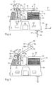
- la figure 4 est une vue d'élévation en plan du déclencheur électromagnétique des figures précédentes, sans son couvercle, représenté dans une première position d'équilibre stable de l'armature mobile ;
- la figure 5 est une vue analogue à la figure 4, dans une deuxième position d'équilibre stable de l'armature mobile ;
- la figure 6 est une vue similaire aux figures 4 et 5, dans une troisième position d'équilibre stable de l'armature mobile ;
- la figure 7 est une vue en plan de dessus du déclencheur électromagnétique de la figure 6 ;
- la figure 8 est une vue en coupe d'élévation longitudinale selon la ligne VIII - VIII de la figure 7 ;
- la figure 9 est une vue en perspective du déclencheur électromagnétique des figures précédentes, dépourvu de son socle et de son couvercle ainsi que du bobinage de la bobine, dans la position de la figure 4 ;
- la figure 10 est une vue en perspective du déclencheur électromagnétique de la figure 9, selon un autre angle de vue ;
- la figure 11 est une vue en plan de dessus de l'armature mobile d'un déclencheur selon l'invention ;
- la figure 12 est une vue en plan d'élévation longitudinale de l'armature mobile de la figure 11 ;
- la figure 13 est une vue en perspective d'une pièce de guidage de l'armature mobile d'un déclencheur électromagnétique selon l'invention ;
- la figure 14 est une vue en plan d'élévation longitudinale de la pièce de guidage de la figure 13 ;
- la figure 15 est une vue en plan de dessus de la pièce de guidage de la figure 13 ;
- la figure 16 est une vue en plan d'élévation longitudinale de l'armature fixe d'un déclencheur électromagnétique selon l'invention ;
- la figure 17 est une vue en plan d'élévation transversale de l'armature fixe de la figure 16 ;
- la figure 18 est une vue en perspective du socle du déclencheur électromagnétique des figures 1 à 8 ;
- la figure 19 est une vue en plan de dessus du socle de la figure 18 ;
- la figure 20 est une vue en coupe d'élévation longitudinale du socle des figures 18 et 19, selon la ligne XX - XX de la figure 19 ;
- la figure 21 est une vue en coupe d'élévation longitudinale du couvercle du déclencheur électromagnétique de la figure 2, représenté seul ;
- la figure 22 est une vue en plan d'élévation longitudinale de la carcasse de la bobine d'un déclencheur électromagnétique selon l'invention ;
- la figure 23 est une vue en plan de dessous de la carcasse de la figure 22 ;
- la figure 24 est une vue en coupe d'élévation longitudinale de la bobine du déclencheur électromagnétique des figures 1 à 8, selon la ligne XXIV - XXIV de la figure 7 ;
- la figure 25 est une vue en plan d'un picot entrant dans la réalisation de la bobine de la figure 24.
- une direction L longitudinale orientée depuis une localisation dite arrière vers une localisation opposée dite avant ;
- une direction T transversale ; et
- une direction E d'élévation, orientée depuis une localisation dite « basse » ou « inférieure » vers une localisation opposée dite « haute » ou supérieure.
- un premier jeu J1 entre la face avant 104 de la branche avant 8 et la face arrière 109 du trou 94 de l'âme 93 en regard ;
- un deuxième jeu J2 entre la face arrière 105 de la branche avant 8 et la face avant 108 du trou 94 de l'âme 93 en regard ;
- un troisième J3 et un quatrième J4 jeux entre les faces latérales respectives 106, 107, 110, 111 de la branche avant 8 et du trou 94 de l'âme 93 en regard.
Claims (14)
- Déclencheur électromagnétique comportant un circuit électromagnétique (5) comprenant une armature fixe (6) ainsi qu'une armature mobile (7) susceptible d'occuper deux positions d'équilibre stable, à savoir une position de travail dans laquelle elle se trouve plaquée contre l'armature fixe (6) et ferme le circuit électromagnétique (5), et une position de repos dans laquelle elle est écartée de l'armature fixe (6) et ouvre le circuit électromagnétique (5), caractérisé en ce que l'armature mobile (7) est apte à occuper une troisième position d'équilibre stable dans laquelle elle est écartée de l'armature fixe (6) au-delà de la position de repos.
- Déclencheur électromagnétique selon la revendication 1, caractérisé en ce qu'il comprend une plaquette (31) fixée à l'armature fixe (6) et par rapport à laquelle est montée pivotante l'armature mobile (7).
- Déclencheur électromagnétique selon la revendication 2, caractérisé en ce que ladite armature mobile (7) est sollicitée vers sa position de repos par un ressort de rappel (17) ancré d'une part dans ladite armature mobile (7), et d'autre part sur ladite plaquette (31).
- Déclencheur électromagnétique selon la revendication 2 ou la revendication 3, caractérisé en ce que ladite plaquette (31) comporte une surface d'appui ((35) contre laquelle est susceptible de s'appliquer, sous l'action du ressort de rappel (17), une partie biseautée (26) de l'armature mobile (7), ladite partie biseautée (26) formant un axe (A) de pivotement de l'armature mobile (7).
- Déclencheur électromagnétique selon la revendication 4, caractérisé en ce que la plaquette (31) comporte un logement (43) situé à distance de l'armature fixe (6), susceptible de recevoir l'armature mobile (7) dans sa troisième position d'équilibre stable.
- Déclencheur électromagnétique selon la revendication 5, caractérisé en ce que, dans sa troisième position de repos, l'armature mobile (7) se trouve maintenue dans ledit logement (43) sous l'action du ressort de rappel (17).
- Déclencheur électromagnétique selon la revendication 6, caractérisé en ce que l'armature mobile (7) présente une butée (50, 51) venant s'appliquer, sous l'action du ressort de rappel, contre une surface d'appui (47) dudit logement (43), ladite butée (50, 51) étant distincte de ladite partie biseautée (26).
- Déclencheur électromagnétique selon la revendication 7, caractérisé en ce que ladite armature mobile (7) présente un trou traversant (39) pour l'ancrage du ressort (17), et en ce qu'il existe un porte-à-faux entre ce trou (39) et ladite butée (50, 51).
- Déclencheur électromagnétique selon l'une des revendications 5 à 8, caractérisé en ce que ladite plaquette (31) comporte une patte (33, 34) qui dépasse de l'armature fixe (6) et présente une surface formant ladite surface d'appui (35) contre laquelle est susceptible de s'appliquer ladite partie biseautée (26) de l'armature mobile (7), cette patte (33, 34) étant prolongée, au-delà de l'armature fixe (6), par une extension coudée (42) en forme de crochet qui forme ledit logement (43).
- Déclencheur électromagnétique selon la revendication 9, caractérisé en ce que la plaquette (31) comporte deux pattes (33, 34) semblables qui encadrent l'armature mobile (7) dont une partie (37), dans laquelle est ancré le ressort de rappel (17), se trouve, en étant libre de se mouvoir, entre les pattes (33, 34).
- Déclencheur électromagnétique selon l'une des revendications 2 à 10, caractérisé en ce que l'armature mobile (7) se présente sous la forme d'une palette.
- Déclencheur électromagnétique selon l'une des revendications 2 à 11, caractérisé en ce que l'armature fixe (6) est en forme de U, et comporte une première et une deuxième branches (8, 9) reliées par une base (10), ladite plaquette (31) étant fixée à ladite deuxième branche (9).
- Déclencheur électromagnétique selon la revendication 12, caractérisé en ce qu'il comporte un boítier (2) dans lequel est disposé le circuit électromagnétique (5), ledit boítier (2) comportant un socle (3) coiffé d'un couvercle (4), socle (3) sur lequel repose l'armature fixe (6).
- Déclencheur électromagnétique selon la revendication 13, caractérisé en ce que l'armature fixe (6) est assujettie audit boítier (2), sa base (10) se trouvant immobilisée, serrée, entre le socle (3) et le couvercle (4).
Applications Claiming Priority (2)
| Application Number | Priority Date | Filing Date | Title |
|---|---|---|---|
| FR0104724 | 2001-04-06 | ||
| FR0104724A FR2823371B1 (fr) | 2001-04-06 | 2001-04-06 | Declencheur electromagnetique comportant un circuit electromagnetique dont l'armature mobile est apte a occuper trois positions d'equilibre stable |
Publications (2)
| Publication Number | Publication Date |
|---|---|
| EP1248278A1 true EP1248278A1 (fr) | 2002-10-09 |
| EP1248278B1 EP1248278B1 (fr) | 2005-10-19 |
Family
ID=8862044
Family Applications (1)
| Application Number | Title | Priority Date | Filing Date |
|---|---|---|---|
| EP02290799A Expired - Lifetime EP1248278B1 (fr) | 2001-04-06 | 2002-03-29 | Déclencheur électromagnétique comportant un circuit électromagnétique dont l'armature mobile est apte à accuper trois positions d'équilibre stable |
Country Status (7)
| Country | Link |
|---|---|
| EP (1) | EP1248278B1 (fr) |
| CN (1) | CN1249759C (fr) |
| AT (1) | ATE307385T1 (fr) |
| DE (1) | DE60206682T2 (fr) |
| ES (1) | ES2248495T3 (fr) |
| FR (1) | FR2823371B1 (fr) |
| PL (1) | PL200461B1 (fr) |
Families Citing this family (2)
| Publication number | Priority date | Publication date | Assignee | Title |
|---|---|---|---|---|
| CN110767407B (zh) * | 2019-10-14 | 2021-03-05 | 西南交通大学 | 一种多稳态电磁操动机构 |
| FR3118334B1 (fr) | 2020-12-18 | 2022-12-23 | Legrand France | Appareil électrique de protection d’une installation électrique en courant alternatif |
Citations (3)
| Publication number | Priority date | Publication date | Assignee | Title |
|---|---|---|---|---|
| US1512064A (en) * | 1921-03-31 | 1924-10-21 | Krupp Ag | Automatic electromagnetic switch |
| FR2620264A1 (fr) * | 1987-09-03 | 1989-03-10 | Merlin Gerin | Declencheur magnetique a articulation a couteau |
| EP0337900A1 (fr) * | 1988-04-14 | 1989-10-18 | Merlin Gerin | Déclencheur électromagnétique à haute sensibilité |
-
2001
- 2001-04-06 FR FR0104724A patent/FR2823371B1/fr not_active Expired - Lifetime
-
2002
- 2002-03-29 EP EP02290799A patent/EP1248278B1/fr not_active Expired - Lifetime
- 2002-03-29 AT AT02290799T patent/ATE307385T1/de not_active IP Right Cessation
- 2002-03-29 DE DE60206682T patent/DE60206682T2/de not_active Expired - Lifetime
- 2002-03-29 ES ES02290799T patent/ES2248495T3/es not_active Expired - Lifetime
- 2002-04-04 PL PL353196A patent/PL200461B1/pl unknown
- 2002-04-05 CN CN02106154.8A patent/CN1249759C/zh not_active Expired - Fee Related
Patent Citations (3)
| Publication number | Priority date | Publication date | Assignee | Title |
|---|---|---|---|---|
| US1512064A (en) * | 1921-03-31 | 1924-10-21 | Krupp Ag | Automatic electromagnetic switch |
| FR2620264A1 (fr) * | 1987-09-03 | 1989-03-10 | Merlin Gerin | Declencheur magnetique a articulation a couteau |
| EP0337900A1 (fr) * | 1988-04-14 | 1989-10-18 | Merlin Gerin | Déclencheur électromagnétique à haute sensibilité |
Also Published As
| Publication number | Publication date |
|---|---|
| CN1380670A (zh) | 2002-11-20 |
| FR2823371A1 (fr) | 2002-10-11 |
| EP1248278B1 (fr) | 2005-10-19 |
| DE60206682T2 (de) | 2006-07-13 |
| DE60206682D1 (de) | 2005-11-24 |
| CN1249759C (zh) | 2006-04-05 |
| ATE307385T1 (de) | 2005-11-15 |
| PL353196A1 (en) | 2002-10-07 |
| FR2823371B1 (fr) | 2004-11-26 |
| PL200461B1 (pl) | 2009-01-30 |
| ES2248495T3 (es) | 2006-03-16 |
Similar Documents
| Publication | Publication Date | Title |
|---|---|---|
| EP0570647B1 (fr) | Mécanisme de serrure pour disjoncteur et disjoncteurs l'incorporant | |
| FR2716594A1 (fr) | Support pour radiotéléphone portatif . | |
| EP0016169B1 (fr) | Boucle pour ceinture de securite de vehicules | |
| EP1586726B1 (fr) | Mécanisme d'ouverture/fermeture de portière de véhicule automobile | |
| EP1901327B1 (fr) | Mécanisme à deux positions stables et dispositif de commande électrique le comportant | |
| EP0205379B1 (fr) | Boucle, notamment de ceinture de sécurité | |
| FR2541815A1 (fr) | Relais electromagnetique a armature articulee | |
| EP1248277B1 (fr) | Déclencheur électromagnétique comportant un circuit électromagnétique reposant sur un socle déformable élastiquement et déclencheur électromagnétique comprenant une bobine flottante | |
| FR2555803A1 (fr) | Dispositif d'accouplement entre un commutateur electromagnetique et une unite a contacts auxiliaires montee de facon amovible sur celui-ci | |
| FR2555805A1 (fr) | Relais electromagnetique a peigne | |
| EP1248278B1 (fr) | Déclencheur électromagnétique comportant un circuit électromagnétique dont l'armature mobile est apte à accuper trois positions d'équilibre stable | |
| EP0325501B1 (fr) | Perfectionnement aux interrupteurs à coupure automatique, notamment aux interrupteurs différentiels et disjoncteurs | |
| FR2823370A1 (fr) | Declencheur electromagnetique comprenant une armature mobile et une armature fixe sur laquelle est encliquetee une piece de guidage de l'armature mobile | |
| EP0526356B1 (fr) | Dispositif de signalisation de déclenchement d'un disjoncteur | |
| FR2674679A1 (fr) | Mecanisme de serrure pour disjoncteur. | |
| FR2553247A3 (fr) | Telephone, en particulier telephone pour automobile, equipe d'un dispositif de verrouillage perfectionne | |
| EP1650780B1 (fr) | Déclencheur électromagnétique et appareil de protection électronique le comportant | |
| EP0551777B1 (fr) | Appareils interrupteurs à commande électromagnétique et manuelle | |
| EP0218517B1 (fr) | Boucle, notamment de ceinture de sécurité pour véhicule automobile | |
| EP3392086B1 (fr) | Agencement d'anneau d'arrimage sur une structure de support tel que le bord de rive ou un plancher notamment de chargement d'un véhicule de transport | |
| EP0866483A1 (fr) | Coupe-batterie bi-stable à verrouillage mécanique | |
| FR2686189A1 (fr) | Perfectionnement aux appareils interrupteurs a commande electromagnetique et manuelle, tels que relais, contacteurs ou contacteurs jour-nuit. | |
| EP1756917B1 (fr) | Systeme de connexion automatique de deux circuits electriques d'un vehicule | |
| EP1632970B1 (fr) | Déclencheur électromagnétique et appareil de coupure électronique le comportant | |
| FR2830121A1 (fr) | Disjoncteur automatique |
Legal Events
| Date | Code | Title | Description |
|---|---|---|---|
| PUAI | Public reference made under article 153(3) epc to a published international application that has entered the european phase |
Free format text: ORIGINAL CODE: 0009012 |
|
| AK | Designated contracting states |
Kind code of ref document: A1 Designated state(s): AT BE CH CY DE DK ES FI FR GB GR IE IT LI LU MC NL PT SE TR |
|
| AX | Request for extension of the european patent |
Free format text: AL;LT;LV;MK;RO;SI |
|
| 17P | Request for examination filed |
Effective date: 20021118 |
|
| AKX | Designation fees paid |
Designated state(s): AT BE CH CY DE DK ES FI FR GB GR IE IT LI LU MC NL PT SE TR |
|
| GRAP | Despatch of communication of intention to grant a patent |
Free format text: ORIGINAL CODE: EPIDOSNIGR1 |
|
| GRAS | Grant fee paid |
Free format text: ORIGINAL CODE: EPIDOSNIGR3 |
|
| GRAA | (expected) grant |
Free format text: ORIGINAL CODE: 0009210 |
|
| AK | Designated contracting states |
Kind code of ref document: B1 Designated state(s): AT BE CH CY DE DK ES FI FR GB GR IE IT LI LU MC NL PT SE TR |
|
| PG25 | Lapsed in a contracting state [announced via postgrant information from national office to epo] |
Ref country code: NL Free format text: LAPSE BECAUSE OF FAILURE TO SUBMIT A TRANSLATION OF THE DESCRIPTION OR TO PAY THE FEE WITHIN THE PRESCRIBED TIME-LIMIT Effective date: 20051019 Ref country code: IE Free format text: LAPSE BECAUSE OF FAILURE TO SUBMIT A TRANSLATION OF THE DESCRIPTION OR TO PAY THE FEE WITHIN THE PRESCRIBED TIME-LIMIT Effective date: 20051019 Ref country code: FI Free format text: LAPSE BECAUSE OF FAILURE TO SUBMIT A TRANSLATION OF THE DESCRIPTION OR TO PAY THE FEE WITHIN THE PRESCRIBED TIME-LIMIT Effective date: 20051019 |
|
| REG | Reference to a national code |
Ref country code: GB Ref legal event code: FG4D Free format text: NOT ENGLISH |
|
| REG | Reference to a national code |
Ref country code: CH Ref legal event code: EP |
|
| REG | Reference to a national code |
Ref country code: IE Ref legal event code: FG4D Free format text: LANGUAGE OF EP DOCUMENT: FRENCH |
|
| REF | Corresponds to: |
Ref document number: 60206682 Country of ref document: DE Date of ref document: 20051124 Kind code of ref document: P |
|
| PG25 | Lapsed in a contracting state [announced via postgrant information from national office to epo] |
Ref country code: SE Free format text: LAPSE BECAUSE OF FAILURE TO SUBMIT A TRANSLATION OF THE DESCRIPTION OR TO PAY THE FEE WITHIN THE PRESCRIBED TIME-LIMIT Effective date: 20060119 Ref country code: DK Free format text: LAPSE BECAUSE OF FAILURE TO SUBMIT A TRANSLATION OF THE DESCRIPTION OR TO PAY THE FEE WITHIN THE PRESCRIBED TIME-LIMIT Effective date: 20060119 |
|
| GBT | Gb: translation of ep patent filed (gb section 77(6)(a)/1977) |
Effective date: 20060108 |
|
| REG | Reference to a national code |
Ref country code: GR Ref legal event code: EP Ref document number: 20060400004 Country of ref document: GR |
|
| REG | Reference to a national code |
Ref country code: ES Ref legal event code: FG2A Ref document number: 2248495 Country of ref document: ES Kind code of ref document: T3 |
|
| PG25 | Lapsed in a contracting state [announced via postgrant information from national office to epo] |
Ref country code: PT Free format text: LAPSE BECAUSE OF FAILURE TO SUBMIT A TRANSLATION OF THE DESCRIPTION OR TO PAY THE FEE WITHIN THE PRESCRIBED TIME-LIMIT Effective date: 20060320 |
|
| PG25 | Lapsed in a contracting state [announced via postgrant information from national office to epo] |
Ref country code: CH Free format text: LAPSE BECAUSE OF NON-PAYMENT OF DUE FEES Effective date: 20060331 Ref country code: LI Free format text: LAPSE BECAUSE OF NON-PAYMENT OF DUE FEES Effective date: 20060331 Ref country code: BE Free format text: LAPSE BECAUSE OF NON-PAYMENT OF DUE FEES Effective date: 20060331 Ref country code: LU Free format text: LAPSE BECAUSE OF NON-PAYMENT OF DUE FEES Effective date: 20060331 Ref country code: MC Free format text: LAPSE BECAUSE OF NON-PAYMENT OF DUE FEES Effective date: 20060331 |
|
| NLV1 | Nl: lapsed or annulled due to failure to fulfill the requirements of art. 29p and 29m of the patents act | ||
| REG | Reference to a national code |
Ref country code: IE Ref legal event code: FD4D |
|
| PLBE | No opposition filed within time limit |
Free format text: ORIGINAL CODE: 0009261 |
|
| STAA | Information on the status of an ep patent application or granted ep patent |
Free format text: STATUS: NO OPPOSITION FILED WITHIN TIME LIMIT |
|
| 26N | No opposition filed |
Effective date: 20060720 |
|
| REG | Reference to a national code |
Ref country code: CH Ref legal event code: PL |
|
| PGFP | Annual fee paid to national office [announced via postgrant information from national office to epo] |
Ref country code: GB Payment date: 20070314 Year of fee payment: 6 |
|
| PGFP | Annual fee paid to national office [announced via postgrant information from national office to epo] |
Ref country code: TR Payment date: 20070213 Year of fee payment: 6 |
|
| BERE | Be: lapsed |
Owner name: SERD SOC. D'ETUDE ET DE REALISATION DE DISJONCTEU Effective date: 20060331 |
|
| PGFP | Annual fee paid to national office [announced via postgrant information from national office to epo] |
Ref country code: GR Payment date: 20070216 Year of fee payment: 6 |
|
| PG25 | Lapsed in a contracting state [announced via postgrant information from national office to epo] |
Ref country code: GR Free format text: LAPSE BECAUSE OF NON-PAYMENT OF DUE FEES Effective date: 20060120 |
|
| GBPC | Gb: european patent ceased through non-payment of renewal fee |
Effective date: 20080329 |
|
| PG25 | Lapsed in a contracting state [announced via postgrant information from national office to epo] |
Ref country code: CY Free format text: LAPSE BECAUSE OF FAILURE TO SUBMIT A TRANSLATION OF THE DESCRIPTION OR TO PAY THE FEE WITHIN THE PRESCRIBED TIME-LIMIT Effective date: 20051019 |
|
| PGFP | Annual fee paid to national office [announced via postgrant information from national office to epo] |
Ref country code: AT Payment date: 20090218 Year of fee payment: 8 Ref country code: ES Payment date: 20090304 Year of fee payment: 8 |
|
| PG25 | Lapsed in a contracting state [announced via postgrant information from national office to epo] |
Ref country code: GB Free format text: LAPSE BECAUSE OF NON-PAYMENT OF DUE FEES Effective date: 20080329 |
|
| PG25 | Lapsed in a contracting state [announced via postgrant information from national office to epo] |
Ref country code: AT Free format text: LAPSE BECAUSE OF NON-PAYMENT OF DUE FEES Effective date: 20100329 |
|
| PG25 | Lapsed in a contracting state [announced via postgrant information from national office to epo] |
Ref country code: TR Free format text: LAPSE BECAUSE OF NON-PAYMENT OF DUE FEES Effective date: 20100929 |
|
| REG | Reference to a national code |
Ref country code: ES Ref legal event code: FD2A Effective date: 20111118 |
|
| PG25 | Lapsed in a contracting state [announced via postgrant information from national office to epo] |
Ref country code: ES Free format text: LAPSE BECAUSE OF NON-PAYMENT OF DUE FEES Effective date: 20100330 |
|
| PG25 | Lapsed in a contracting state [announced via postgrant information from national office to epo] |
Ref country code: TR Free format text: LAPSE BECAUSE OF NON-PAYMENT OF DUE FEES Effective date: 20080329 |
|
| PGFP | Annual fee paid to national office [announced via postgrant information from national office to epo] |
Ref country code: DE Payment date: 20150311 Year of fee payment: 14 |
|
| REG | Reference to a national code |
Ref country code: FR Ref legal event code: PLFP Year of fee payment: 15 |
|
| REG | Reference to a national code |
Ref country code: DE Ref legal event code: R119 Ref document number: 60206682 Country of ref document: DE |
|
| PG25 | Lapsed in a contracting state [announced via postgrant information from national office to epo] |
Ref country code: DE Free format text: LAPSE BECAUSE OF NON-PAYMENT OF DUE FEES Effective date: 20161001 |
|
| REG | Reference to a national code |
Ref country code: FR Ref legal event code: PLFP Year of fee payment: 16 |
|
| REG | Reference to a national code |
Ref country code: FR Ref legal event code: PLFP Year of fee payment: 17 |
|
| PGFP | Annual fee paid to national office [announced via postgrant information from national office to epo] |
Ref country code: FR Payment date: 20180328 Year of fee payment: 17 Ref country code: IT Payment date: 20180309 Year of fee payment: 17 |
|
| PG25 | Lapsed in a contracting state [announced via postgrant information from national office to epo] |
Ref country code: IT Free format text: LAPSE BECAUSE OF NON-PAYMENT OF DUE FEES Effective date: 20190329 Ref country code: FR Free format text: LAPSE BECAUSE OF NON-PAYMENT OF DUE FEES Effective date: 20190331 |