EP1248280A1 - Tragrahmen für Schattenmaske für Farbbildröhre und Verfahren zur Herstellung - Google Patents
Tragrahmen für Schattenmaske für Farbbildröhre und Verfahren zur Herstellung Download PDFInfo
- Publication number
- EP1248280A1 EP1248280A1 EP02290805A EP02290805A EP1248280A1 EP 1248280 A1 EP1248280 A1 EP 1248280A1 EP 02290805 A EP02290805 A EP 02290805A EP 02290805 A EP02290805 A EP 02290805A EP 1248280 A1 EP1248280 A1 EP 1248280A1
- Authority
- EP
- European Patent Office
- Prior art keywords
- frame
- uprights
- lateral
- wall
- upright
- Prior art date
- Legal status (The legal status is an assumption and is not a legal conclusion. Google has not performed a legal analysis and makes no representation as to the accuracy of the status listed.)
- Granted
Links
- 238000004519 manufacturing process Methods 0.000 title claims description 25
- 238000000034 method Methods 0.000 title claims description 20
- 238000005304 joining Methods 0.000 claims abstract description 22
- 229910052751 metal Inorganic materials 0.000 claims description 47
- 239000002184 metal Substances 0.000 claims description 47
- 238000003466 welding Methods 0.000 claims description 36
- 229910045601 alloy Inorganic materials 0.000 claims description 28
- 239000000956 alloy Substances 0.000 claims description 28
- 238000005520 cutting process Methods 0.000 claims description 15
- 239000000463 material Substances 0.000 claims description 14
- 238000005452 bending Methods 0.000 claims description 13
- 229910000831 Steel Inorganic materials 0.000 claims description 6
- 239000010959 steel Substances 0.000 claims description 6
- 238000005476 soldering Methods 0.000 claims description 5
- 239000011572 manganese Substances 0.000 claims description 4
- PWHULOQIROXLJO-UHFFFAOYSA-N Manganese Chemical compound [Mn] PWHULOQIROXLJO-UHFFFAOYSA-N 0.000 claims description 3
- 238000004026 adhesive bonding Methods 0.000 claims description 3
- 230000009466 transformation Effects 0.000 claims description 3
- UGKDIUIOSMUOAW-UHFFFAOYSA-N iron nickel Chemical compound [Fe].[Ni] UGKDIUIOSMUOAW-UHFFFAOYSA-N 0.000 claims description 2
- 229910052748 manganese Inorganic materials 0.000 claims description 2
- 229910000734 martensite Inorganic materials 0.000 claims description 2
- 230000000704 physical effect Effects 0.000 claims description 2
- 238000004881 precipitation hardening Methods 0.000 claims description 2
- 238000001330 spinodal decomposition reaction Methods 0.000 claims description 2
- 238000010438 heat treatment Methods 0.000 description 6
- 230000010339 dilation Effects 0.000 description 4
- 230000006835 compression Effects 0.000 description 3
- 238000007906 compression Methods 0.000 description 3
- 238000009826 distribution Methods 0.000 description 3
- 230000000694 effects Effects 0.000 description 3
- 238000010894 electron beam technology Methods 0.000 description 2
- 239000011521 glass Substances 0.000 description 2
- 238000005382 thermal cycling Methods 0.000 description 2
- 238000011282 treatment Methods 0.000 description 2
- 229910000990 Ni alloy Inorganic materials 0.000 description 1
- 230000005540 biological transmission Effects 0.000 description 1
- 210000000988 bone and bone Anatomy 0.000 description 1
- 239000003086 colorant Substances 0.000 description 1
- 238000004891 communication Methods 0.000 description 1
- 238000010276 construction Methods 0.000 description 1
- 238000002788 crimping Methods 0.000 description 1
- 238000013016 damping Methods 0.000 description 1
- 238000006073 displacement reaction Methods 0.000 description 1
- 239000011888 foil Substances 0.000 description 1
- 238000013003 hot bending Methods 0.000 description 1
- 238000009434 installation Methods 0.000 description 1
- 230000010354 integration Effects 0.000 description 1
- 239000012528 membrane Substances 0.000 description 1
- 239000007769 metal material Substances 0.000 description 1
- 238000004021 metal welding Methods 0.000 description 1
- 229910052759 nickel Inorganic materials 0.000 description 1
- PXHVJJICTQNCMI-UHFFFAOYSA-N nickel Substances [Ni] PXHVJJICTQNCMI-UHFFFAOYSA-N 0.000 description 1
- 238000010008 shearing Methods 0.000 description 1
- 239000007787 solid Substances 0.000 description 1
- 238000010792 warming Methods 0.000 description 1
- 238000005493 welding type Methods 0.000 description 1
Images





Classifications
-
- H—ELECTRICITY
- H01—ELECTRIC ELEMENTS
- H01J—ELECTRIC DISCHARGE TUBES OR DISCHARGE LAMPS
- H01J29/00—Details of cathode-ray tubes or of electron-beam tubes of the types covered by group H01J31/00
- H01J29/02—Electrodes; Screens; Mounting, supporting, spacing or insulating thereof
- H01J29/06—Screens for shielding; Masks interposed in the electron stream
- H01J29/07—Shadow masks for colour television tubes
-
- H—ELECTRICITY
- H01—ELECTRIC ELEMENTS
- H01J—ELECTRIC DISCHARGE TUBES OR DISCHARGE LAMPS
- H01J9/00—Apparatus or processes specially adapted for the manufacture, installation, removal, maintenance of electric discharge tubes, discharge lamps, or parts thereof; Recovery of material from discharge tubes or lamps
- H01J9/02—Manufacture of electrodes or electrode systems
- H01J9/14—Manufacture of electrodes or electrode systems of non-emitting electrodes
- H01J9/142—Manufacture of electrodes or electrode systems of non-emitting electrodes of shadow-masks for colour television tubes
-
- H—ELECTRICITY
- H01—ELECTRIC ELEMENTS
- H01J—ELECTRIC DISCHARGE TUBES OR DISCHARGE LAMPS
- H01J29/00—Details of cathode-ray tubes or of electron-beam tubes of the types covered by group H01J31/00
- H01J29/02—Electrodes; Screens; Mounting, supporting, spacing or insulating thereof
- H01J29/06—Screens for shielding; Masks interposed in the electron stream
- H01J29/07—Shadow masks for colour television tubes
- H01J29/073—Mounting arrangements associated with shadow masks
Definitions
- the invention relates to a shadow mask support frame for a tube. cathode color display.
- Color display cathode ray tubes have a metallic foil pierced with a multitude of holes or slots, called “shadow mask”, placed between the electron gun and the display screen.
- This shadow mask is intended to obtain a clear image in ensuring that the impacts of electron beams on the display screen are precisely located on the photophores arranged on the screen of viewing.
- Shadow masks are supported by generally shaped frames rectangular which hold them in position in the vicinity of the display screen and, possibly, ensure that they are stretched, so to limit the deformations resulting from the local heating generated by electron beams.
- a shadow mask support frame has two lateral uprights formed by metal tubes or angles and two end posts constituted by angles or by tubes placed on the side uprights and assembled by welding at the contact points.
- the tubes or angles must be relatively thick to obtain sufficient rigidity.
- the frames thus formed are suitable with stretched shadow masks but have the drawback of being heavy and difficult to manufacture with good geometric precision.
- a frame for a shadow mask is made up of angles made from thin strips which are assembled by welding.
- the frame is produced by stamping a sheet metallic, generally rectangular, with a central cutout also rectangular.
- the frames thus produced have the advantage of being light but have the disadvantage of being not very rigid and, therefore, poorly suitable for supporting stretched shadow masks.
- the hollow body consists of one or more membranes thin metal folded to form all or part of the body hollow and assembled, for example, by welding.
- Such a shadow mask support frame which is light, rigid and easy to manufacture is well suited to the case of generally planar frames, that is to say frames whose longitudinal axes of the uprights are substantially in the same plane, the longitudinal uprights connecting to the end posts at the corners of the frame.
- the end posts are generally formed by angles comprising a first flat wall situated in a frame reference plane substantially parallel to the position of the shadow mask carried by the frame and a second wall perpendicular to the first wall through which is exerted on the frame a compression force, during welding of the shadow mask, so the frame is stretched, when the compressive force is released on the end posts of the frame.
- the lateral uprights of the frame generally have a part main substantially straight and two end parts ensuring the connection and junction with the end posts.
- Each of the end portions of the side uprights has a section of junction with the end post which is generally perpendicular or orthogonal to the main branch of the lateral upright corresponding and which is fixed on an end post, in a provision perpendicular to the upright.
- the section of junction at the end lateral uprights is placed in abutment against the external surface of the first wall of the end post and welded in this position on the end post.
- Welding of the abutment parts of the lateral uprights on the uprights end is achieved by a welding process such as the process TIG or the MIG process.
- a welding process such as the process TIG or the MIG process.
- Such methods require the use of angles or very thick tubes, because they release a significant energy which is likely to deform the structures and melt the angles or tubes, if their walls are too thin.
- the side uprights of the frame are generally made by bending a thick tube or a bar having a nominal square section or rectangular.
- the tube or bar is strongly deformed in the folding area. There is usually a deformation in "bone” or “barrel” shape.
- the end posts which are slightly curved, are generally made by cold or hot bending a thick shaped bar de L. Obtaining precise shapes and dimensions of the end posts request to take great care in the folding operations of the thick bar.
- the frames obtained must therefore be rectified after assembly, to obtain the dimensional accuracy necessary for manufacturing shadow mask frames of cathode ray tubes.
- cathode ray tube screen tiles which are themselves thick and therefore heavy.
- the cost of a cathode ray tube is determined in largely by the amount of glass used to manufacture the screen and of the cone of the cathode ray tube. When the screen panel is thick, the cone of the tube is itself massive. Frame cathode ray tubes heavy are therefore extremely expensive.
- this frame which is suspended in the front face of the screen panel is liable to drop out during impacts undergone by the tube, for example during transport or, it can be produce damage to the frame's attachment pins on the slab.
- the weight of the frame also requires the use of hanging springs of high power.
- a massive and heavy frame has a high heat capacity and heats up slowly when the cathode ray tube is put into service. Therefore, the time required to obtain good stability of the tube colors can be relatively long.
- the temperature of the frame can reach 80 to 100 ° C.
- the entire frame and shadow mask is subjected to high temperatures in the range 500 ° C.
- the second solution in the case of a massive and heavy frame, requires the use of a massive and heavy compensation bar.
- the deformation is therefore not at all homogeneous along the length end posts.
- the object of the invention is therefore to propose a mask support frame shadow for a color viewing tube, shaped general rectangular, comprising two end posts substantially rectilinear and parallel to each other comprising at least one wall substantially perpendicular to a frame reference plane, one edge of which is intended to receive a shadow mask in an arrangement substantially parallel to the frame reference plane, and two lateral uprights general tubular each having a main part having an axis substantially straight and two end portions each connected to a connecting section to an end post, in an orthogonal arrangement relative to the frame reference plane and parallel to the wall substantially flat of the end upright, the lateral uprights having axes parallel to each other located in a plane parallel to the reference plane of the frame, this shadow mask support frame allowing a realization light and not very massive of the frame, according to dimensions and geometry very precise, while obtaining very good properties of rigidity and mechanical resistance of the frame.
- each of the joining sections is in contact by a lateral face with an internal face of the wall substantially perpendicular perpendicular to the frame reference plane, so that the uprights of the frame end rests on the junction sections of the uprights side.
- the two amounts of ends each comprise at least one first wall substantially plane in the frame reference plane and a second wall constituting the planar wall substantially perpendicular to the reference plane and therefore to the first wall, having in common with the first wall a direction edge longitudinal of the end upright and the two lateral uprights have connecting sections to the end posts, in a orthogonal arrangement relative to the main part of the lateral upright and perpendicular to the first wall of the end post and parts main having axes parallel to each other located in a parallel plane to the frame reference plane, in an arrangement offset from the frame reference plane; in this case, each of the joining sections is fitted into an end post through the first wall of the end upright and fixed against the inner face of the second perpendicular wall to the reference plane.
- the end parts or extensions lateral uprights constitute two to two of the uprights continuous, in the direction of the end posts joining the ends main parts of the lateral uprights, two by two to constitute a complete plan framework.
- Each of the continuous uprights of the parallel plane frame at an end post comprises at least one connecting section.
- Each of the continuous uprights parallel to an end upright may have two joining sections spaced from each other in the longitudinal direction of the continuous upright and interconnected by a part of connection between the extensions of the lateral uprights to constitute the continuous amount.
- Each of the continuous amounts may include a single junction section arranged in a middle part of the continuous upright common to the two extensions of the lateral uprights constituting the continuous amount.
- Figure 1 is a perspective view of a shadow mask following the invention and according to a first embodiment.
- Figure 2 is a perspective view of a shadow mask following the invention and according to a second embodiment.
- Figure 3 is a plan view of a metal strip used for the manufacture of a lateral upright of a frame according to the invention as shown according to figure 2.
- Figure 4 is a perspective view of a junction part between an end post and a side post of a mask support frame as shown in Figure 2.
- Figure 5 is a plan view of a metal strip for manufacturing of a lateral upright of a following shadow mask support frame a first variant of the second embodiment.
- Figure 6 is a perspective view of a junction part between an end post and a side post of a mask support frame according to the first variant.
- Figure 7 is a perspective view of an end post of a frame according to the invention and according to the second embodiment shown in figure 2.
- Figure 8 is a perspective view of a second alternative embodiment of the joining part between a lateral upright and an end upright of a mask support frame according to the invention and according to the second embodiment.
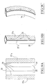
- FIGS. 9A, 9B and 9C are views showing the production of a lateral upright of a frame according to the invention making it possible to relax the constraints in the shadow mask.
- FIG. 9A is a plan view of a metal strip for making the lateral upright.
- FIG. 9B is a perspective view of the folded lateral upright and welded.
- FIG. 9C is a perspective view of the lateral upright heated to a heat treatment temperature, during its manufacture.
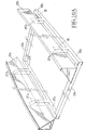
- Figures 10A and 10B are perspective views of a frame along the second embodiment and respectively according to a third and a fourth variant.
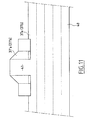
- Figure 11 is a plan view of a cut strip for the realization an end portion of the side uprights of the frame shown in Figure 10A or Figure 10B.
- Figures 12A and 12B are sectional plan views of the strip shown in Figure 11, to make an opening along a first and according to a second variant, in a lateral upright.
- Figure 13 is a simplified plan view of a plan frame consisting by the lateral uprights of a frame as shown in FIG. 10A or Figure 10B.
- Figure 14 shows the plan frame of Figure 13 in a deformed state.
- the mask support frame 1 has two end posts 2a and 2b and two lateral uprights 3a and 3b constituting, with the uprights end 2a and 2b, a generally rectangular frame.
- the end posts 2a and 2b can be constituted by angles each having a first wall 4a (or 4b), the first walls 4a and 4b of the end posts 2a and 2b being in the same plane constituting the frame reference plane.
- the end posts have second walls 5a and 5b respectively perpendicular to the first walls 4a and 4b and having in common with these is an internal edge such as 6a in the direction longitudinal of the end post.
- the shadow mask must be fixed according to external edges 5'a and 5'b of the end posts 2a and 2b, in an arrangement substantially parallel to the frame reference plane.
- the lateral uprights 3a and 3b each consist of an element tubular or a bar, for example with a square section, and comprise a central part of substantially rectilinear shape and two end parts junction of the lateral upright with the end uprights.
- the axes of the main parts of the lateral uprights are parallel between them and located in a plane parallel to the frame reference plane and offset from this plane in a direction perpendicular to the plane frame reference.
- the end parts or extensions of the lateral uprights (such that 7a) comprise two successive parts directed at 90 ° relative to the axis of the main part of the lateral upright and perpendicular to each other.
- the terminal section 7'a of the end portion 7a of the lateral upright 3a which is orthogonal to the longitudinal direction of the main part of the lateral upright 3a is arranged relative to the end upright 2a, of so that the wall 5a is in abutment, by a face directed towards the inside of the frame 1, on the side wall of the terminal section 7'a.
- the end section 7'a is fitted in the end upright, in a perpendicular direction to the longitudinal direction of the end post 2a.
- junction end section 7 ′ a of the end portion 7a of the lateral upright 3a is attached and fixed, for example by welding, against the inner face of the wall 5a of the end upright.
- Each of the end portions of the lateral uprights 3a and 3b is similarly fixed, by embedding and fixing plan on plan, inside an end post, so as to form the frame 1 of form overall rectangular.
- the deformation in compression of the frame, when mounting the shadow mask which must be welded along the edges 5'a and 5'b is carried out via the seconds walls 5a and 5b of the end posts 2a and 2b.
- connection end parts such as 7a of the lateral uprights without this force of thrust produces significant stresses in the connection area between the junction section 7'a at the end of the end portion 7a of the upright lateral and the inner face of the second wall 5a of the end upright 2a.
- the resistance of the frame depends little on the resistance of the connection between the connecting sections such as 7'a and the internal faces of the seconds walls of the corresponding end posts.
- junction section and the second wall of the frame end post is only to fix the position of the section junction such as 7'a, along the length of the end post.
- Such elements can be used to make frames for shadow mask according to the invention which are both light and rigid.
- the shadow mask support frame 1 shown in Figure 2 is entirely produced by cutting, folding and assembling thin strips, in a metallic material adapted to the properties sought for the shadow mask support frame.
- the end posts 2a and 2b and the side posts 3a and 3b of frame 1 according to the second embodiment shown in Figure 2 are made in the form of beams or tubes with thin walls at times high inertia.
- the end portions such as 7a of lateral uprights 3a and 3b are fitted inside the uprights end 2a and 2b corresponding and fixed on these uprights through a junction end section such as 7'a.
- the end posts 2a and 2b are made in the form of beams substantially straight with triangular cross-section and the side uprights 3a and 3b, in the form of tubes, for example with a square or rectangular section.
- the end posts 2a and 2b can be obtained from a thin metallic strip of generally rectangular shape folded along the edge internal 6a common to the first wall 4a and to the second wall 5a of the upright end and along a second internal edge 6'a at the junction of the first wall 4a and a third inclined wall 9a of the end upright 2a for closing the end post section and obtaining a high rigidity beam with triangular section from a metal sheet thin having for example a thickness between 0.5 and 1.5 mm.
- the outer edge of the second wall of the end post 2a can be pressed and folded inwards, at around 90 ° to constitute the rim 5'a for fixing the shadow mask, of generally curved shape.
- the lateral uprights 3a and 3b have a straight main part and are fixed to the end posts 2a and 2b by means of end parts such as 7a having an end joining section 7a which is engaged in an opening passing through the first wall 4a the corresponding end post 2a, in an arrangement adjacent to the second wall 5a of the end post, so that the section of junction 7'a is fitted into the end upright 2a and fixed flat on plane, by its lateral face directed towards the outside of the frame, on the internal surface of the second wall 5a of the end upright 2a.
- each of the lateral uprights 3a and 3b has two end parts or extensions, one of which allows the connection of the upright lateral to a first end upright and the other of which allows connection from the lateral upright to the second end upright.
- the longitudinal directions of the end posts are parallel between them and the first walls 4a and 4b of the end posts constitute a frame reference plane substantially parallel to the surface of fixing of the shadow mask formed by the edges 5'a and 5'b of the uprights end 2a and 2b.
- the axes of the main rectilinear parts of the lateral uprights 3a and 3b which are parallel to each other lie in a plane parallel to the plane reference frame defined by the walls 4a and 4b of the end posts and offset from the reference plane, in a perpendicular direction common to the reference plane and to the plane of the axes of the lateral sides.
- the faces of the connecting sections such as 7'a or 7 “have added and fixed plane on plane on the second walls of the end posts ensuring the transmission by thrust of the forces exerted on the end posts of the frame, when mounting the shadow mask are fixed in place on the second walls of the end posts, for example by welding, riveting, soldering or bonding, the mechanical strength of the bond depending on the support surface such that 11 is not critical due to the support of the end part of the lateral upright against an internal face of the upright end.
- Terminal junction sections such as 7'a and 7 "a can be also fixed by clipping on the end posts.
- the end uprights may have along the edges of the openings of passage of junction sections, attachment parts (for example folded edges of a sheet metal constituting the wall of the upright) and the sections junction can include depressions to receive the parties attachment, when engaging the connecting sections in the openings end posts.
- the lateral uprights are fixed on the end posts.
- the end portions of the uprights lateral such as 7a constitute an elbow making it possible to offset the zone fitting of the connecting section such as 7'a relative to the end longitudinal of the corresponding end post 2a.
- the through openings made through the first wall 4a the end post such as 2a and allowing the fitting of parts end of the lateral uprights 3a and 3b are each offset relative to at the corresponding end of the upright 2a towards the central part of the upright, so that the support zones 11 offset towards the central part of the end post ensure a more homogeneous deformation of the end upright when compressive forces are exerted at the time fixing the shadow mask on the fixing edges 5'a and 5'b.
- Each of the joining parts of the lateral uprights such as 7a has a first rectilinear part perpendicular to the axial direction of the main part of the upright and a second rectilinear part constituting the junction section 7'a perpendicular to the first straight part and orthogonal to the axial direction of the corresponding lateral upright.
- Each of the lateral uprights 3a and 3b is fixed at its ends, of the same way, in an end upright.
- FIG 3 there is shown in plan a thin metal strip 10 intended to constitute a connection end part such as shown in Figure 4 of a lateral upright 3a as shown in the figure 2.
- a first part 12 of the metal strip comprising five zones ends delimited by fold lines constitutes the end zone the main part of the lateral upright which has four flat walls and a flap 12a intended to come to be superimposed during folding at the zone 12'a to assemble the main part of the upright by welding plan on plan of zones 12a and 12'a folded over one another.
- the welding is carried out by laser in transparency and the lower wall formed by the zone 12'a on which the zone 12a is folded so as to present a slightly greater angle at 90 ° with the adjacent wall. Therefore, during welding, a support is produced. of the two walls 12a, 12'a one on the other by exerting pressure on the wall 12a. The wall 12'a is thus effectively pressed against the wall 12a by elastic return.
- the area generally designated by the reference 13 in Figure 3 generally corresponds to the first rectilinear part of the part end 7a of the lateral upright.
- Zone 14 generally corresponds to the junction section 7'a at the end of the lateral upright.
- the end upright 2a produced by folding a substantially rectangular strip comprises, in its first wall 4a, two openings 15 and 15 'intended to receive the sections end junction of two lateral uprights embedded in the upright end 2a.
- the openings 15 and 15 ' are adjacent to the common internal edge 6a to the first and second walls 4a, 5a of the upright 2a and we clean, when cutting openings 15 and 15 ', tabs 16 and 17 for holding and fixing a recessed end portion of an upright lateral on three edges of the embedding openings such as 15 and 15 '.
- the assembly and attachment of the different walls of a lateral upright as well as the fixing of the lateral upright on the end upright, for example by means of the tabs 16 and 17 and of the bearing surface 11, can be produced according to zones of transparent laser welding 18.
- the fixing of the walls and the stiffening of the uprights end 2a in the form of triangular section beams are made at the interior of cavities 19 produced by stamping the wall 9a of the upright end in different places distributed along the length of the upright end, below the rim 5'a for fixing the shadow mask.
- the wall 9a of the end upright in the zones deformed by stamping constituting the cavities 19 is in contact with the second wall 5a of the end post, so that the two can be welded walls in contact with each other inside the cavities 19, for example by means of a laser beam.
- Figures 5 and 6 show a first variant of the second embodiment of an end portion of a lateral upright, in its junction zone with an end post.
- FIG 5 there is shown a metal strip 20 used for the manufacture of a lateral upright of a frame according to the first variant of the second embodiment.
- FIG. 5 in the same way as in FIG. 3, there is shown in dotted lines the fold lines of the strip 20 and in solid lines the cutting lines to obtain the end portion 7a of an upright lateral 3a as shown in FIG. 6 in an assembly position to an end post 2a identical to the amount shown on the figure 7.
- the side upright shown in Figure 6 and obtained from the strip 20 shown in FIG. 5 does not include a connection elbow for the junction section 7'a end, the junction section 7'a being connected directly to right angle to the main part of the lateral upright 3a.
- junction end section 7'a of the lateral upright 3a is engaged in an opening 15 of the first wall 4a of the end post 2a, in a zone of the end post located at a certain distance from its longitudinal end.
- the strip 20 has a part 22, substantially identical to the part 12 of the strip 10 shown on the Figure 3, and which comprises five successive adjacent zones separated by fold lines to obtain the straight main part of the upright 3a having the shape of a square section tube.
- the end zone 22a constitutes a covering wall or flap intended to come to bear on the opposite zone 22'a constituting a wall the main part of the upright 3a on which the flap 22a can be welded by transparent laser beam.
- the zone 23 of the strip 20 constitutes the junction section 7'a of the upright 3a and has two flaps which can be beam welded laser against two lateral faces of the straight main part of the upright lateral 3a.
- junction section 7'a of the lateral upright 3a is embedded in the end post, so that one of its faces corresponding to the central zone 22 "a of the strip 20 comes into plan-on-plan contact with the inner surface of the second wall 5a of the end upright 2a, on which it is fixed in position, for example by laser welding or by any other fixing method, such as soldering, riveting or bonding.
- the walls in plan-to-plan contact of the lateral upright 3a and of the upright end 2a constitute the support zone 11 through which thrust forces exerted on the end post 2a can be transmitted to the lateral upright 3a.
- junction section 7'a of the lateral upright 3a engaged in the opening 15 can be held and fixed in position by means of the tabs 16 and 17 and the contact surface along the support zone 11 of the upright end 2a.
- FIG. 8 a second variant of the part is shown. end of a lateral upright 3a ensuring its junction with the upright end 2a
- the end upright 2a has, at its longitudinal ends, dimples of substantially square shape, such as the dimple 21 shown in Figure 8, intended to ensure the passage of the end of a straight main part of a lateral upright 3a which can have the shape of a square section tube which has an end zone of connection 7a having the shape of a right angle bend, both of which successive parts have axes arranged in a perpendicular plane to the axis of the main rectilinear part of the lateral upright 3a.
- the opening 21 crosses the inclined wall 9a of the end upright 2a which comprises in addition an opening 25 passing through the first wall 4a of the end upright 2a, in an area some distance from the end longitudinal of the end post 2a placed in an arrangement adjacent to the second wall 5a of the end post, in which is embedded an end portion of the junction section 7'a of the lateral upright 3a.
- one of the side surfaces of the end portion 7a comprising the end section 7'a is in plan-on-plan contact with the second wall 5a of the end upright 2a, on which it is fixed, by example by welding, to form the support zone 11.
- FIG. 9A a section of a metal strip has been represented. 30 used for the production of a lateral upright of a mask support frame shade according to the invention by a cutting, folding technique and welding, as described above with reference to FIGS. 3 and 5.
- the strip 30 is not produced homogeneously from a metal strip of a single material but has a central part 26 made of a low coefficient alloy expansion and two lateral parts 27a and 27'a in a coefficient alloy high dilation or vice versa, depending on the desired effect.
- Longitudinal fold lines 28 separate the central area 26 of the strip of the lateral zones 27a and 27'a and the central part 26 in three central zones 29.
- the two walls 27a and 27'a are welded to each other, for example by welding points 31 produced for example by a laser beam.
- the lateral upright 3a thus obtained takes on an arcuate shape when heated, for example to a temperature treatment temperature of 500 ° C, during the manufacture of the support frame shadow mask.
- the tubular side uprights of the frame keep good elastic properties when working at temperature internal working of the cathode ray tube, i.e. at a temperature from 80 to 120 ° C.
- a first alloy whose high expansion coefficient is of the order of 12.10 -6 / ° K and an alloy with a low coefficient of dilation, for example of the order of 1.10 -6 / ° K.
- the thickness of the central strip and the side strips is also chosen so as to obtain the deformation effect of the support frame.
- FIGS. 10A and 10B a support frame is shown. shadow mask according to the invention and respectively, according to a third and fourth variants of the second embodiment.
- the frames according to the variants shown in Figure 10A and 10B are produced in a similar manner to the frame according to the first variant of realization (figure 2), by cutting, folding and assembling thin strips metal.
- These frames include end posts 32a and 32b which can be made in the form of section beams or tubes triangular.
- the lateral uprights 33a and 33b can be constituted by beams or tubes with square or rectangular cross-section.
- each of the ends of the side uprights door, via an end portion 7a of the upright, a junction section 7'a orthogonal to the frame reference plane.
- the parts end 37a, 37b and 38a, 38b of the two lateral uprights 33a and 33b constitute two by two of the continuous uprights of a flat frame joining each two ends of the side uprights in a direction parallel to the end posts 32a and 32b.
- Each of the end parts 37a, 37b, 38a and 38b constituting the continuous uprights of the flat frame having the direction end uprights is integral with a respective junction section 37'a, 37'b, 38'a, 38'b orthogonal to the reference plane of the defined frame by the walls 34a and 34b of the end posts.
- connection part constituting the central part of the continuous amount of the plan frame.
- This arrangement has the advantage of allowing better control of rectangularity of the frame.
- the frame shown in Figure 10A has on each end portion 37a, 37b, 38a, 38b of the side uprights, a connecting section respective 37'a, 37'b, 38'a, 38'b the junction sections located on the same continuous amount of the plane frame being arranged on either side of the axis of symmetry of the frame parallel to the lateral uprights 33a and 33b.
- junction sections 37'a and 37'b or 38'a and 38'b and therefore the length of the connecting part of the continuous upright can be chosen as in the case of the embodiment shown in the Figure 2, to optimize the mechanical behavior of the end posts 32a and 32b. In particular, this distance can be reduced to zero and in this case, the two joining sections 37'a and 37'b or 38'a and 38'b are combined along sections 37'a and 38'a as shown in the figure 10B relating to the latter embodiment.
- the frame shown in Figure 10B does not have on each amount continuous 37a and 37b or 38a and 38b of the planar frame only one junction section 37'a or 38'a in a middle part of the continuous amount common to two extensions of the lateral uprights constituting the continuous upright.
- junction sections 37'a and 38'a are fitted in the end posts, each through an opening crossing the wall 34a or 34b of the corresponding amount parallel to the plane frame reference and are supported by an external support surface 41 on the internal face of the corresponding wall 35a or 35b perpendicular to the frame reference plane.
- the junction sections 37'a and 38'a in support plane on plane on the second walls 35a and 35b of the end posts can be fixed by welding against the end posts.
- the plan of reference defined by the first walls 34a and 34b of the end posts can be more or less distant from the plan frame formed by the uprights side.
- the first walls 34a and 34b of the end posts can be superimposed on the upper faces of the side uprights or placed at a certain distance above the lateral uprights.
- the side uprights can be obtained by cutting, bending and welding a metal strip 40.
- the folded lines of the metal strip are represented by dotted lines thin 40 and with solid lines the cutting lines.
- the whole frame plan consisting of lateral sides and their extensions is obtained either by folding and welding a single thin metal strip, either by folding and welding of several strips in the form of tubes which are then assembled at right angles to their ends via walls or tabs, Welding and possibly assembly of the parts of the flat frame can be made, by a laser beam, in transparency.
- the metal strip 40 (for making a single piece of two aligned extensions 37a and 37b on the lateral sides) has a rectangular main part in which four lines of folding to form four sides of a square section tube and a flap assembly and a protruding part on one edge of the cut thin strip along a contour allowing a junction section to be obtained by folding 37'a (or 38'a) closed by a flap.
- the metal strip for the realization of a continuous amount such that 37a-37b or 38a-38b of the planar frame has two similar projecting parts to the protruding part of the strip 40 shown in Figure 11.
- These protruding parts may be at any distance from each other following the length of the metal strip and are connected by part of the metal strip intended to constitute the connection part of the upright continued.
- the projecting part of the metal strip 40 includes a part central unit 41 in one piece with the median zone, along its length, of the continuous upright consisting of aligned extensions 37a and 37b or 38a and 38b, and two symmetrical lateral parts separated from the main part of the strip 40 by a cut-out intended to constitute by folding the faces of the junction section 37'a or 38'a and an assembly flap.
- the lateral sides are made from a strip or a part of rectangular band similar to the main part of band 40.
- the end posts which can also be obtained by cutting, bending and welding of metal strips have openings in the middle part of their faces 34a and 34b defining the plane of frame reference to allow passage of the junction sections 37'a and 38'a. These openings made by cutting the metal sheet of the end uprights may include tabs for securing the sections junction along their edges, which are reserved during cutting openings.
- the face of the upright continuous which consists of two aligned extensions such as 37a and 37b on a lateral side, intended to be folded along the edge of the strip 40 comprising the junction section may comprise, in its middle part coming inside the junction section in the folded state, a cutout 42 or 42 ' allowing the internal part of the junction section to be put into communication with the internal part of the lateral upright.
- Cutout 42 ( Figure 12A) is made so as to form two fixing tabs 43a and 43b of the joining section, along the entire width of the cut face.
- the cut 42 '( Figure 12B) is made so forming three fixing tabs 43'a, 43'b and 43'c along a part only of the width of the cut face which are folded according to respective transverse and longitudinal fold lines.
- the lateral uprights must be deformed in bending in the plane of the frame, so that the concavities of the deformed lateral uprights are oriented towards the inside of the frame.
- This deformation of the lateral uprights generates a flexion of their extensions which bring one closer to the other, the middle parts of these extensions, as represented by the curved lines in solid lines and in dotted in FIG. 14, respectively showing an external face of the lateral uprights and their extensions in the deformed state.
- the extensions 37a-37b and 38a-38b of the lateral uprights 33a and 33b can also behave like bimetallic strips which on heating, bend in the plane of the frame so that the concavities of the extensions 37a-37b and 38a-38b are oriented towards the outside of the frame.
- bimetallic strip deformations of the uprights lateral and their extensions reduce the forces generated in the connection zones between the side uprights and their extensions.
- first blades 44a and 44b in materials with a coefficient of expansion different from that of the material of which the side uprights, are attached and fixed plan on plan on two sides of the lateral uprights perpendicular to the reference plane of the frame, inside the tubular upright. Blades could be attached also on faces parallel to the reference plane, inside the amounts.
- the material from which the blades 44a and 44b are made may have a coefficient of expansion greater or less than that of the material of which made up the lateral uprights, along the faces of the lateral uprights on which they are fixed (faces directed towards the outside of the frame, as shown in Figures 13 and 14 or faces facing inwards).
- second blades 45a and 45b can also be attached and fixed plan on plan, inside tubular extensions, on faces of the extensions 37a and 37b of the lateral uprights perpendicular to the reference plane of the frame and directed outward or inward of the frame.
- blades can be fixed on surfaces internal faces of uprights and / or perpendicular extensions to the frame reference plane directed towards the inside or outside of the frame. This provision can also be applied to the frame according to the first and second embodiments.
- the end posts When performing the installation of the shadow mask, the end posts can be brought closer to each other, without undergoing deformation by bending or with very little deformation.
- the blades 44a, 44b and 45a, 45b allow, during thermal cycling, to deform the uprights of the frame in opposite directions (bending outwards for the uprights lateral 33a and 33b, as shown in solid lines, and bending inwards for extensions 37a and 37b, as shown in dotted lines). Therefore, we limit the stresses exerted in the corners of the frame plan consisting of the lateral uprights and their extensions.
- the median areas of connection of the end posts are few distorted or displaced. The end posts fixed by their central part in these zones are therefore little deformed and their displacement produces a relaxation of the shadow mask.
- alloys with high elastic limit will be used and with a high Young's modulus.
- low-alloys will be used coefficient of thermal expansion to reduce the stresses to be applied to the frame and therefore the weight of the frame.
- the realization according to the invention makes it possible to divide the mass of the frame by at least 2.5 and also considerably reduce the weight of glass used for manufacture of cathode ray tubes.
- the end posts of the frame according to the invention can be produced, as described above, in the form of a section angle in L or in the form of a beam with closed triangular section obtained from a folded and welded metal strip. End posts may also be formed by hollow profiles with triangular section.
- the side uprights of the following shadow mask support frame the invention are generally of tubular shape with closed section, by square or rectangular example and can be obtained by cutting and folding of a metal strip, as indicated above, or under the in the form of closed hollow profiles having a cross-section, for example in the form of quadrilateral (square, rectangular or trapezoidal shape) or under bar shape.
- the shadow mask support frame according to the invention comprises generally four uprights which are made separately and assembled between them by embedding and connection of plan type on plan.
- the frame generally has a shape and a structure allowing to pass a practically continuous line closed inside of the uprights of the frame, in the longitudinal direction of the uprights and along the entire periphery of the frame.
- the continuous line is not planar but has the shape of a left curve.
- the frame uprights can be linked, for example, by clinching, clipping, riveting, soldering, medium resistance welding frequency, capacitive discharge welding, crimping, bonding or screwing or by low energy TIG or MIG welding.
- the assembly of the bands, after folding to achieve the lateral sides of the frame can be achieved by other techniques than welding laser in transparency which was considered above.
- the assembly of the side uprights of the frame to the end uprights can be made in the vicinity of the longitudinal ends of the uprights end or in areas far from the longitudinal ends towards the central part of the end uprights, i.e. between a longitudinal end and the central part of the upright or else in the vicinity of the central part of the upright.
- the radius of curvature of the elbows can be of the order of magnitude of the thickness of the strip used, that is to say from 0.5 to 1.5 mm.
- the connecting end parts of the side uprights can have very little or even no play with respect to the first wall of the end upright in which they are embedded, the deformation of the end uprights obtainable by plane sliding on plane the first wall of the end posts on the end portions of connection of the lateral uprights.
- the support frame for a stretched shadow mask according to the invention can have a welding rim of the shadow mask obtained directly by folding and / or stamping, without subsequent rectification of the profile.
- the shadow mask frame according to the invention can be used in any color display cathode ray tube.
Landscapes
- Engineering & Computer Science (AREA)
- Manufacturing & Machinery (AREA)
- Electrodes For Cathode-Ray Tubes (AREA)
- Mutual Connection Of Rods And Tubes (AREA)
- Spectrometry And Color Measurement (AREA)
- Assembled Shelves (AREA)
Applications Claiming Priority (4)
| Application Number | Priority Date | Filing Date | Title |
|---|---|---|---|
| FR0104527A FR2823006A1 (fr) | 2001-04-03 | 2001-04-03 | Cadre support de masque d'ombre pour tube cathodique de visualisation en couleur et procede de fabrication |
| FR0104527 | 2001-04-03 | ||
| FR0114066A FR2823007B1 (fr) | 2001-04-03 | 2001-10-30 | Cadre support de masque d'ombre pour tube cathodique de visualisation en couleur et procede de fabrication |
| FR0114066 | 2001-10-30 |
Publications (2)
| Publication Number | Publication Date |
|---|---|
| EP1248280A1 true EP1248280A1 (de) | 2002-10-09 |
| EP1248280B1 EP1248280B1 (de) | 2005-11-02 |
Family
ID=26212949
Family Applications (1)
| Application Number | Title | Priority Date | Filing Date |
|---|---|---|---|
| EP02290805A Expired - Lifetime EP1248280B1 (de) | 2001-04-03 | 2002-03-29 | Tragrahmen für Schattenmaske für Farbbildröhre und Verfahren zur Herstellung |
Country Status (16)
| Country | Link |
|---|---|
| US (1) | US6703774B2 (de) |
| EP (1) | EP1248280B1 (de) |
| JP (1) | JP3548559B2 (de) |
| KR (1) | KR100826950B1 (de) |
| CN (1) | CN1244125C (de) |
| AT (1) | ATE308797T1 (de) |
| BR (1) | BR0201079A (de) |
| CA (1) | CA2378688A1 (de) |
| CZ (1) | CZ20021145A3 (de) |
| DE (1) | DE60206993D1 (de) |
| FR (2) | FR2823006A1 (de) |
| MX (1) | MXPA02003371A (de) |
| PL (1) | PL353153A1 (de) |
| RU (1) | RU2002108344A (de) |
| SG (1) | SG100787A1 (de) |
| TW (1) | TW543062B (de) |
Families Citing this family (3)
| Publication number | Priority date | Publication date | Assignee | Title |
|---|---|---|---|---|
| JP5640346B2 (ja) * | 2009-09-16 | 2014-12-17 | Jfeスチール株式会社 | 多角形閉断面構造部品の製造方法 |
| US20190296687A1 (en) * | 2018-03-23 | 2019-09-26 | Nextracker Inc. | Structural beam for solar tracker |
| CN108977763B (zh) * | 2018-06-20 | 2020-02-14 | 武汉华星光电半导体显示技术有限公司 | 有源矩阵有机发光二极管精细荫罩组件及其制造方法 |
Citations (2)
| Publication number | Priority date | Publication date | Assignee | Title |
|---|---|---|---|---|
| WO2000011700A1 (en) * | 1998-08-25 | 2000-03-02 | Sony Electronics Inc. | Aperture grille structure for a cathode ray tube |
| EP1032016A1 (de) * | 1999-02-19 | 2000-08-30 | Imphy Ugine Precision | Tragrahmen für eine Schattenmaske einer Kathodenstrahlröhrenanzeige |
Family Cites Families (9)
| Publication number | Priority date | Publication date | Assignee | Title |
|---|---|---|---|---|
| JPH0992144A (ja) * | 1995-09-19 | 1997-04-04 | Sony Corp | フレーム部材溶接治具 |
| TW408346B (en) * | 1997-04-09 | 2000-10-11 | Samsung Electronics Co Ltd | CRT support frame and monitor comprising the same |
| KR100428968B1 (ko) * | 1997-07-04 | 2004-07-16 | 삼성에스디아이 주식회사 | 칼라 음극선관용 섀도우마스크 프레임 조립체 |
| JP2000048735A (ja) * | 1998-07-27 | 2000-02-18 | Mitsubishi Electric Corp | 陰極線管 |
| KR100554418B1 (ko) * | 1998-12-21 | 2006-06-14 | 엘지전자 주식회사 | 음극선관 |
| KR20000054916A (ko) * | 1999-02-01 | 2000-09-05 | 김순택 | 음극선관용 마스크 어셈블리 |
| KR20000073438A (ko) * | 1999-05-11 | 2000-12-05 | 구자홍 | 칼라음극선관용 섀도우마스크 |
| KR100339376B1 (ko) * | 1999-08-13 | 2002-06-03 | 구자홍 | 칼라 음극선관용 지지프레임 |
| JP2001126631A (ja) * | 1999-10-28 | 2001-05-11 | Nec Kansai Ltd | シャドウマスク構体およびカラーブラウン管 |
-
2001
- 2001-04-03 FR FR0104527A patent/FR2823006A1/fr active Pending
- 2001-10-30 FR FR0114066A patent/FR2823007B1/fr not_active Expired - Fee Related
-
2002
- 2002-03-27 CA CA002378688A patent/CA2378688A1/fr not_active Abandoned
- 2002-03-28 SG SG200201887A patent/SG100787A1/en unknown
- 2002-03-28 JP JP2002090817A patent/JP3548559B2/ja not_active Expired - Fee Related
- 2002-03-29 TW TW091106354A patent/TW543062B/zh active
- 2002-03-29 DE DE60206993T patent/DE60206993D1/de not_active Expired - Lifetime
- 2002-03-29 EP EP02290805A patent/EP1248280B1/de not_active Expired - Lifetime
- 2002-03-29 AT AT02290805T patent/ATE308797T1/de not_active IP Right Cessation
- 2002-04-01 US US10/109,862 patent/US6703774B2/en not_active Expired - Fee Related
- 2002-04-02 CZ CZ20021145A patent/CZ20021145A3/cs unknown
- 2002-04-02 CN CNB021087857A patent/CN1244125C/zh not_active Expired - Fee Related
- 2002-04-02 RU RU2002108344/09A patent/RU2002108344A/ru not_active Application Discontinuation
- 2002-04-02 MX MXPA02003371A patent/MXPA02003371A/es unknown
- 2002-04-03 PL PL02353153A patent/PL353153A1/xx unknown
- 2002-04-03 BR BR0201079-8A patent/BR0201079A/pt not_active Application Discontinuation
- 2002-04-03 KR KR1020020018229A patent/KR100826950B1/ko not_active Expired - Fee Related
Patent Citations (2)
| Publication number | Priority date | Publication date | Assignee | Title |
|---|---|---|---|---|
| WO2000011700A1 (en) * | 1998-08-25 | 2000-03-02 | Sony Electronics Inc. | Aperture grille structure for a cathode ray tube |
| EP1032016A1 (de) * | 1999-02-19 | 2000-08-30 | Imphy Ugine Precision | Tragrahmen für eine Schattenmaske einer Kathodenstrahlröhrenanzeige |
Also Published As
| Publication number | Publication date |
|---|---|
| SG100787A1 (en) | 2003-12-26 |
| KR100826950B1 (ko) | 2008-05-02 |
| CZ20021145A3 (cs) | 2002-11-13 |
| JP2002313253A (ja) | 2002-10-25 |
| MXPA02003371A (es) | 2004-07-16 |
| CN1244125C (zh) | 2006-03-01 |
| US20020140355A1 (en) | 2002-10-03 |
| BR0201079A (pt) | 2003-01-07 |
| TW543062B (en) | 2003-07-21 |
| EP1248280B1 (de) | 2005-11-02 |
| PL353153A1 (en) | 2002-10-07 |
| FR2823006A1 (fr) | 2002-10-04 |
| CN1379432A (zh) | 2002-11-13 |
| ATE308797T1 (de) | 2005-11-15 |
| FR2823007A1 (fr) | 2002-10-04 |
| DE60206993D1 (de) | 2005-12-08 |
| JP3548559B2 (ja) | 2004-07-28 |
| RU2002108344A (ru) | 2003-12-20 |
| US6703774B2 (en) | 2004-03-09 |
| KR20020079444A (ko) | 2002-10-19 |
| FR2823007B1 (fr) | 2003-06-27 |
| CA2378688A1 (fr) | 2002-10-03 |
Similar Documents
| Publication | Publication Date | Title |
|---|---|---|
| CA2702908A1 (fr) | Structure d'avion comportant des jonctions d'arrets de raidisseurs | |
| EP0809272B1 (de) | Lochmaskenrahmen einer Kathodenstrahlröhre und Verfahren zu seiner Herstellung | |
| EP0288376B1 (de) | Befestigungseinrichtung für Platten einer Fassadenverkleidung | |
| WO2012098333A1 (fr) | Ferrure multi-branche en materiau composite et procede de fabrication d'une telle ferrure multi-branche | |
| EP2673444A1 (de) | Abstandshalter, verbinder und isolierverglasung | |
| FR2742528A1 (fr) | Echangeur de chaleur a plaque collectrice renforcee, notamment pour vehicule automobile | |
| FR2933059A1 (fr) | Insert de rigidification pour caisse de vehicule automobile | |
| FR2552467A1 (fr) | Structure arquee de couverture d'un milieu, notamment pour serres | |
| CA1029520A (fr) | Structures composites | |
| EP1248280B1 (de) | Tragrahmen für Schattenmaske für Farbbildröhre und Verfahren zur Herstellung | |
| EP1032016B1 (de) | Tragrahmen für eine Schattenmaske einer Kathodenstrahlröhrenanzeige | |
| EP0884444A2 (de) | Eingangstür für ein Lokal | |
| EP1180185A1 (de) | Deckenplatte | |
| EP4344994B1 (de) | Verfahren zum verbinden eines rumpfteils durch schweissen mit verbesserter flexibilität, rumpfteil und so erhaltenes luftfahrzeug | |
| FR3004067A1 (fr) | Profile, notamment metallique, destine a permettre une fixation d'un film sur une structure de serre et systeme de fixation d'un film sur une structure de serre comprenant un tel profile | |
| WO2002005979A1 (fr) | Procede de fabrication d'un element de structure ayant une paroi metallique de forme generale tubulaire et element de structure | |
| EP3186132B1 (de) | Anordnung aus bewehrungseinsätzen mittels eines polymermaterials, insbesondere für eine technische frontseite eines fahrzeugs, besagte anordnung mit verstärkung durch die befestigung davon an einem strukturelement | |
| EP0072333B1 (de) | Verfahren zur Herstellung von vollen und steifen Wandelementen | |
| FR2520044A1 (fr) | Corniere d'angle en tole a estamper destinee a l'assemblage de profiles creux d'entretoisement pour des vitrages isolants | |
| FR2961075A3 (fr) | Paroi prefabriquee ultralegere | |
| FR2734297A1 (fr) | Element de structure pour la realisation d'ossatures de batiments | |
| EP4101720A1 (de) | Fahrgestellstruktur für fahrzeug | |
| BE474931A (de) | ||
| FR2770595A1 (fr) | Element d'assemblage angulaire et ensemble de boites aux lettres comprenant au moins un tel element | |
| BE820534A (fr) | Construction de volet avec des assemblages de panneaux prefabriques mobiles horizontalement |
Legal Events
| Date | Code | Title | Description |
|---|---|---|---|
| PUAI | Public reference made under article 153(3) epc to a published international application that has entered the european phase |
Free format text: ORIGINAL CODE: 0009012 |
|
| 17P | Request for examination filed |
Effective date: 20020628 |
|
| AK | Designated contracting states |
Kind code of ref document: A1 Designated state(s): AT BE CH CY DE DK ES FI FR GB GR IE IT LI LU MC NL PT SE TR |
|
| AX | Request for extension of the european patent |
Free format text: AL;LT PAYMENT 20020628;LV;MK;RO;SI |
|
| AKX | Designation fees paid |
Designated state(s): AT BE CH CY DE DK ES FI FR GB GR IE IT LI LU MC NL PT SE TR |
|
| AXX | Extension fees paid |
Extension state: LT Payment date: 20020628 |
|
| GRAP | Despatch of communication of intention to grant a patent |
Free format text: ORIGINAL CODE: EPIDOSNIGR1 |
|
| GRAS | Grant fee paid |
Free format text: ORIGINAL CODE: EPIDOSNIGR3 |
|
| GRAA | (expected) grant |
Free format text: ORIGINAL CODE: 0009210 |
|
| RAP1 | Party data changed (applicant data changed or rights of an application transferred) |
Owner name: IMPHY ALLOYS |
|
| AK | Designated contracting states |
Kind code of ref document: B1 Designated state(s): AT BE CH CY DE DK ES FI FR GB GR IE IT LI LU MC NL PT SE TR |
|
| AX | Request for extension of the european patent |
Extension state: LT |
|
| PG25 | Lapsed in a contracting state [announced via postgrant information from national office to epo] |
Ref country code: IT Free format text: LAPSE BECAUSE OF FAILURE TO SUBMIT A TRANSLATION OF THE DESCRIPTION OR TO PAY THE FEE WITHIN THE PRESCRIBED TIME-LIMIT;WARNING: LAPSES OF ITALIAN PATENTS WITH EFFECTIVE DATE BEFORE 2007 MAY HAVE OCCURRED AT ANY TIME BEFORE 2007. THE CORRECT EFFECTIVE DATE MAY BE DIFFERENT FROM THE ONE RECORDED. Effective date: 20051102 Ref country code: FI Free format text: LAPSE BECAUSE OF FAILURE TO SUBMIT A TRANSLATION OF THE DESCRIPTION OR TO PAY THE FEE WITHIN THE PRESCRIBED TIME-LIMIT Effective date: 20051102 Ref country code: IE Free format text: LAPSE BECAUSE OF FAILURE TO SUBMIT A TRANSLATION OF THE DESCRIPTION OR TO PAY THE FEE WITHIN THE PRESCRIBED TIME-LIMIT Effective date: 20051102 Ref country code: AT Free format text: LAPSE BECAUSE OF FAILURE TO SUBMIT A TRANSLATION OF THE DESCRIPTION OR TO PAY THE FEE WITHIN THE PRESCRIBED TIME-LIMIT Effective date: 20051102 |
|
| REG | Reference to a national code |
Ref country code: GB Ref legal event code: FG4D Free format text: NOT ENGLISH |
|
| REG | Reference to a national code |
Ref country code: CH Ref legal event code: EP |
|
| GBT | Gb: translation of ep patent filed (gb section 77(6)(a)/1977) |
Effective date: 20051102 |
|
| REF | Corresponds to: |
Ref document number: 60206993 Country of ref document: DE Date of ref document: 20051208 Kind code of ref document: P |
|
| PG25 | Lapsed in a contracting state [announced via postgrant information from national office to epo] |
Ref country code: DK Free format text: LAPSE BECAUSE OF FAILURE TO SUBMIT A TRANSLATION OF THE DESCRIPTION OR TO PAY THE FEE WITHIN THE PRESCRIBED TIME-LIMIT Effective date: 20060202 Ref country code: GR Free format text: LAPSE BECAUSE OF FAILURE TO SUBMIT A TRANSLATION OF THE DESCRIPTION OR TO PAY THE FEE WITHIN THE PRESCRIBED TIME-LIMIT Effective date: 20060202 Ref country code: SE Free format text: LAPSE BECAUSE OF FAILURE TO SUBMIT A TRANSLATION OF THE DESCRIPTION OR TO PAY THE FEE WITHIN THE PRESCRIBED TIME-LIMIT Effective date: 20060202 |
|
| PG25 | Lapsed in a contracting state [announced via postgrant information from national office to epo] |
Ref country code: DE Free format text: LAPSE BECAUSE OF FAILURE TO SUBMIT A TRANSLATION OF THE DESCRIPTION OR TO PAY THE FEE WITHIN THE PRESCRIBED TIME-LIMIT Effective date: 20060203 |
|
| PG25 | Lapsed in a contracting state [announced via postgrant information from national office to epo] |
Ref country code: ES Free format text: LAPSE BECAUSE OF FAILURE TO SUBMIT A TRANSLATION OF THE DESCRIPTION OR TO PAY THE FEE WITHIN THE PRESCRIBED TIME-LIMIT Effective date: 20060213 |
|
| PG25 | Lapsed in a contracting state [announced via postgrant information from national office to epo] |
Ref country code: BE Free format text: LAPSE BECAUSE OF NON-PAYMENT OF DUE FEES Effective date: 20060331 Ref country code: MC Free format text: LAPSE BECAUSE OF NON-PAYMENT OF DUE FEES Effective date: 20060331 Ref country code: LU Free format text: LAPSE BECAUSE OF NON-PAYMENT OF DUE FEES Effective date: 20060331 Ref country code: CH Free format text: LAPSE BECAUSE OF NON-PAYMENT OF DUE FEES Effective date: 20060331 Ref country code: LI Free format text: LAPSE BECAUSE OF NON-PAYMENT OF DUE FEES Effective date: 20060331 |
|
| PG25 | Lapsed in a contracting state [announced via postgrant information from national office to epo] |
Ref country code: PT Free format text: LAPSE BECAUSE OF FAILURE TO SUBMIT A TRANSLATION OF THE DESCRIPTION OR TO PAY THE FEE WITHIN THE PRESCRIBED TIME-LIMIT Effective date: 20060403 |
|
| LTIE | Lt: invalidation of european patent or patent extension |
Effective date: 20051102 |
|
| REG | Reference to a national code |
Ref country code: IE Ref legal event code: FD4D |
|
| PLBE | No opposition filed within time limit |
Free format text: ORIGINAL CODE: 0009261 |
|
| STAA | Information on the status of an ep patent application or granted ep patent |
Free format text: STATUS: NO OPPOSITION FILED WITHIN TIME LIMIT |
|
| 26N | No opposition filed |
Effective date: 20060803 |
|
| REG | Reference to a national code |
Ref country code: CH Ref legal event code: PL |
|
| REG | Reference to a national code |
Ref country code: FR Ref legal event code: ST Effective date: 20061130 |
|
| BERE | Be: lapsed |
Owner name: IMPHY ALLOYS Effective date: 20060331 |
|
| PG25 | Lapsed in a contracting state [announced via postgrant information from national office to epo] |
Ref country code: FR Free format text: LAPSE BECAUSE OF NON-PAYMENT OF DUE FEES Effective date: 20060331 |
|
| PGFP | Annual fee paid to national office [announced via postgrant information from national office to epo] |
Ref country code: GB Payment date: 20080307 Year of fee payment: 7 Ref country code: NL Payment date: 20080221 Year of fee payment: 7 |
|
| PG25 | Lapsed in a contracting state [announced via postgrant information from national office to epo] |
Ref country code: TR Free format text: LAPSE BECAUSE OF FAILURE TO SUBMIT A TRANSLATION OF THE DESCRIPTION OR TO PAY THE FEE WITHIN THE PRESCRIBED TIME-LIMIT Effective date: 20051102 |
|
| PG25 | Lapsed in a contracting state [announced via postgrant information from national office to epo] |
Ref country code: CY Free format text: LAPSE BECAUSE OF FAILURE TO SUBMIT A TRANSLATION OF THE DESCRIPTION OR TO PAY THE FEE WITHIN THE PRESCRIBED TIME-LIMIT Effective date: 20051102 |
|
| GBPC | Gb: european patent ceased through non-payment of renewal fee |
Effective date: 20090329 |
|
| NLV4 | Nl: lapsed or anulled due to non-payment of the annual fee |
Effective date: 20091001 |
|
| PG25 | Lapsed in a contracting state [announced via postgrant information from national office to epo] |
Ref country code: NL Free format text: LAPSE BECAUSE OF NON-PAYMENT OF DUE FEES Effective date: 20091001 |
|
| PG25 | Lapsed in a contracting state [announced via postgrant information from national office to epo] |
Ref country code: GB Free format text: LAPSE BECAUSE OF NON-PAYMENT OF DUE FEES Effective date: 20090329 |