EP1248426A2 - Architektur eines ruhenden Modus für niedrige Spitzendurchschnittsleistungsverhältnisse sowie Signaldesignmethode für DMT-Modems - Google Patents
Architektur eines ruhenden Modus für niedrige Spitzendurchschnittsleistungsverhältnisse sowie Signaldesignmethode für DMT-Modems Download PDFInfo
- Publication number
- EP1248426A2 EP1248426A2 EP02100345A EP02100345A EP1248426A2 EP 1248426 A2 EP1248426 A2 EP 1248426A2 EP 02100345 A EP02100345 A EP 02100345A EP 02100345 A EP02100345 A EP 02100345A EP 1248426 A2 EP1248426 A2 EP 1248426A2
- Authority
- EP
- European Patent Office
- Prior art keywords
- mapping
- bits
- signal
- inner code
- subchannel
- Prior art date
- Legal status (The legal status is an assumption and is not a legal conclusion. Google has not performed a legal analysis and makes no representation as to the accuracy of the status listed.)
- Withdrawn
Links
Images


Classifications
-
- H—ELECTRICITY
- H04—ELECTRIC COMMUNICATION TECHNIQUE
- H04L—TRANSMISSION OF DIGITAL INFORMATION, e.g. TELEGRAPHIC COMMUNICATION
- H04L27/00—Modulated-carrier systems
-
- H—ELECTRICITY
- H04—ELECTRIC COMMUNICATION TECHNIQUE
- H04L—TRANSMISSION OF DIGITAL INFORMATION, e.g. TELEGRAPHIC COMMUNICATION
- H04L1/00—Arrangements for detecting or preventing errors in the information received
- H04L1/004—Arrangements for detecting or preventing errors in the information received by using forward error control
- H04L1/0041—Arrangements at the transmitter end
- H04L1/0042—Encoding specially adapted to other signal generation operation, e.g. in order to reduce transmit distortions, jitter, or to improve signal shape
-
- H—ELECTRICITY
- H04—ELECTRIC COMMUNICATION TECHNIQUE
- H04L—TRANSMISSION OF DIGITAL INFORMATION, e.g. TELEGRAPHIC COMMUNICATION
- H04L1/00—Arrangements for detecting or preventing errors in the information received
- H04L1/004—Arrangements for detecting or preventing errors in the information received by using forward error control
- H04L1/0056—Systems characterized by the type of code used
- H04L1/0059—Convolutional codes
- H04L1/006—Trellis-coded modulation
-
- H—ELECTRICITY
- H04—ELECTRIC COMMUNICATION TECHNIQUE
- H04L—TRANSMISSION OF DIGITAL INFORMATION, e.g. TELEGRAPHIC COMMUNICATION
- H04L27/00—Modulated-carrier systems
- H04L27/26—Systems using multi-frequency codes
-
- H—ELECTRICITY
- H04—ELECTRIC COMMUNICATION TECHNIQUE
- H04L—TRANSMISSION OF DIGITAL INFORMATION, e.g. TELEGRAPHIC COMMUNICATION
- H04L27/00—Modulated-carrier systems
- H04L27/26—Systems using multi-frequency codes
- H04L27/2601—Multicarrier modulation systems
- H04L27/2614—Peak power aspects
- H04L27/2615—Reduction thereof using coding
Definitions
- This invention relates to discrete multitone (DMT) modems, such as asymmetric digital subscriber line (ADSL) modems, and more particularly to a power conserving state known as Quiescent mode (Q-mode).
- DMT discrete multitone
- ADSL digital subscriber line
- Q-mode Quiescent mode
- ADSL modems employing DMT modulation are used for internet access.
- the ADSL standard is described in S.Palm (ed), "Asymmetrical Digital Subscriber Line (ADSL) Transceivers," ITU-T Q4/SG15, G.992.1, 1999, incorporated herein by reference.
- ADSL modems are well known. For example see U.S. Patent No. 6,055,268 of Timm et al.
- DMT modems see U.S. Patent No. 5,400,322; 5,479,447;5,317,596 and 5,285,474. These patents are incorporated herein by reference.
- Q-mode is a proposed power conserving idle state that an ADSL modem can enter when it has no data to transmit.
- an ADSL modem should transmit an idle signal in the power conserving state with an average power similar to that of a data signal.
- Pulsating crosstalk occurs when the average power of the signal on the line changes, affecting neighboring lines in a bundle. Since most modems perform better with stationary crosstalk, it is desirable to minimize changes to the average power of the signal on the line.
- PAR peak-to-average ratio
- AFE ADSL analog front end
- the power saving Q-Mode when there is no data to transmit the PAR of the signal is reduced while the average power of the signal remains the same.
- the low PAR Q-mode signal design takes the effects of the AFE into account in finding a low PAR signal.
- the Q-mode signal is tailored to the AFE and loaded subchannels to realize maximum power savings.
- the transmission convergence (TPS-TC) layer converts Idle data into an all zero bit stream which propagates down to the physical layer. If the bits to DMT symbol mapping maps the all zero bit stream to a low PAR DMT symbol, power savings can be achieved in the AFE. Additionally, if the transmitter and receiver process Showtime (normal data transmissions) and Idle data identically, then the transmitter can achieve the power savings without requiring the intervention of the receiver.
- Simulation results illustrate the ability of the proposed architecture and optimization procedure to map an all zero bit stream to a low PAR signal for a variety of channels.
- the architecture section describes the physical layer DMT transmitter architecture used to form the low PAR mapping, and the constraints on the XOR mapping.
- Figure 1 illustrates the proposed architecture for the DMT transmitter.
- the DMT transmitter architecture allows for the alignment of an all zero bit stream with a low PAR DMT symbol.
- the inner code includes no code, TCM, turbo, and LDPC schemes.
- FEC Forward error connection
- XOR mapper 17 provides mapping to all of the bits of the output of the tone ordering.
- the inner code 19 and constellation encoders 21 l -21 n are applied to the output of the XOR mapping 17.
- the Inverse Fast Fourier Transform (IFFT) 23 and symbol inversion 25 are applied to the encoded constellation points.
- IFFT Inverse Fast Fourier Transform
- the XOR mapping 17 is chosen such that it maps an all zero bit stream into a low PAR DMT symbol (its design will be considered in PAR Minimization section).
- the symbol inverter 25, controlled by a pseudo random binary sequence (PRBS), is used to prevent the generation of a transmitted sequence with a period equal to that of the DMT symbol period.
- PRBS pseudo random binary sequence
- the receiver is illustrated in Fig. 2.
- the receiver operations take place in the reverse order with the received signal undergoing analog to digital conversion, symbol inversion 27, Fast Fourier Transform (FFT) processing 28, constellation decoding 29 to bits, innercode decoding 30, XOR inverse mapper 31 providing inverse mapping, tone deordering 32 and FEC 33 decoding.
- FFT Fast Fourier Transform
- XOR inverse mapper 31 providing inverse mapping, tone deordering 32 and FEC 33 decoding.
- the XOR mapping 17 occurs before the inner code 19 at the transmitter, and after the inner code 30 at the receiver. This allows existing constellation mappers, TCM encoders/decoders, and other advanced inner codes to be used without modification.
- Figure 1 shows the XOR mapping 17 being applied to the whole tone ordered bit sequence. However, in the design of the mapping it is often more convenient to think of its effects on each subchannel.
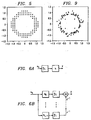
- Figures 3 and 4 show how the mapping can be conceptually viewed as operating on subchannels individually (for the case of no inner code), or operating on a pair of subchannels at a time (for the case of 4D TCM).
- Figure 3 illustrates conceptual view of the XOR mapping with no inner code.
- the XOR mapping can be thought of as divided into N parts (17 l - 17 n ), with each part associated with a subchannel.
- Figure 4 illustrates conceptual view of the XOR mapping 17 l - 17 n with 4D TCM (Trellis-coded modulation) with Trellis encoders 22 l -22 n .
- the XOR mapping can be thought of as divided into N/2 parts 22 l -22 n , with each part associated with 2 subchannels.
- a constraint on the XOR mapping is that for each subchannel it maps a zero input to a constellation point whose power is within some range of the average power of the constellation for that subchannel.
- Figure 5 plots all of the points within ⁇ 1.5 dB of the average power for an 8 bit constellation. In general, this type of power constraint forms a ring. Table 1 lists the number of points within ⁇ 1.5 dB of the average power for 2, ..., 15 bits. The more points in the constellation, the more degrees of freedom there will be in the design of the mappings.
- the mapping design procedure needs to be aware of the effect of the inner code on the mapping.
- the inner code will modify some or all of the bits depending on the choice of the code. Since the goal is to have the signal after the IFFT a low PAR signal, and the code occurs between the mapping and the IFFT, the effects of the code need to be taken into account in the design of the mapping. Different methods for taking into account the effects of the inner code include:
- the performance of the coset 0 constraint will be the worst of the above three.
- Table 1 lists the number of points within ⁇ 1.5 dB of the average power for 2, ..., 15 bits with the label constrained to coset 0. However, in the Simulations section it will be shown that good PAR reduction can even be achieved for this case.
- the 4 lowest power points were counted even though they are less than 1.5 dB below the average power.
- the optimal signal for PAR reduction is dependent on the bit loading (i.e., the channel and noise) and AFE.
- a method is presented which incorporates the bit loading and AFE into the optimization criteria. Note that other optimization methods can be used to form mappings which map a zero bit stream to a low PAR DMT signal.
- X q and x q are related through the discrete Fourier transform (DFT) matrix F and inverse discrete Fourier Transform (IDFT) matrix F H :
- DFT discrete Fourier transform
- IDFT inverse discrete Fourier Transform
- Q-mode signals typically have some constraint on the constellations of their individual subchannels.
- C model the constraint on the Q-mode constellation such that C maps its input to a valid Q-mode symbol (e.g., if the constraint is that the allowed constellation points for an individual subcharge are within ⁇ 1.5 dB of the average power of the original constellation for that subchannel, then C will quantitize that component of its input to an allowed point).
- X q is a valid Q-mode signal
- X q C(X q ).
- a valid Q-mode signal is mapped to itself by the constraint on the constellation.
- the PAR of a Q-mode signal is defined as: where the infinity norm of x q is the peak of the absolute value of x q , and E denotes ensemble average.
- f M a hardlimiter model of an amplifier
- Typical AFE's have upsamplers and filters before the amplifier. Since the goal is to have a low PAR amplifier input, the effects of the AFE should be taken into account if they alter the PAR.
- the parameter M controls the PAR of the Q-mode signal.
- the perturbation in the update for X q is not strong enough to ensure that X q (t) ⁇ X q (t-1) , even though the desired PAR is exceeded (this is often the case when the constraint C quantizes all of its inputs to 4-QAM, and the amount of clipping is small).
- the value of M can be further reduced to generate stronger perturbations.
- the minimization of M can be incorporated into the iteration. This is done by choosing an initial X q and calculating the value of M such that X q does not clip. M is then reduced, and a new X q is found (through iteration) such that it no longer clips. This process is then repeated, until an X q cannot be found that does not clip for a given M.
- Asynchronous digital subscriber line (ADSL) systems allow for modifications to the bit mapping to be made by the receiver (e.g., using bit swap).
- a method is provided which allows for the XOR mapping to accommodate changes to the bitmap without requiring additional communication between the transmitter and receiver. Additionally, the transmitter can make simple changes to the XOR mapping to refine the PAR of the mapping of the all zero signal without having to retransmit the whole XOR mapping.
- N subchannels e.g. 32, 128 or 256
- the initial master XOR mapping is formed by the transmitter conveying to the receiver a 0 or 1 for each of the N subchannel's B bits. This is done for all subchannels and bits, regardless of how many bits are initially loaded on a subchannel. From the master XOR mapping a current XOR mapping is formed by extracting the number of information bits loaded on each of the subchannels.
- mappings formed for two subchannels at a time e.g., N /2 pairs of subchannels each with a maximum of 2 B - 1 uncoded bits.
- a current XOR mapping is formed by taking the first 4 bits from subchannel 0, the first 3 bits from subchannel 1, the first 2 bits from subchannel 2, and no bits from subchannel 3.
- a new current XOR mapping is formed by taking the first 4 bits from subchannel 0, the first 2 bits from subchannel 1, the first 3 bits from subchannel 2, and no bits from subchannel 3.
- the transmitter can send the receiver a message which contains the subchannel number and new XOR mapping for the B bits. Thus it is not necessary to send a new mapping for all subchannels each time the transmitter wants to update the mapping on only a few subchannels.
- Table 4 shows the average power and PAR for a zero bit stream mapped with the two described constraints and a Showtime signal for comparison.
- the PAR of the original DMT signal is approximately 15.5 dB at a frame clipping probability of 10 -6 .
- the PAR minimization algorithm tends to reduce the overall power by 1 - 1.2 dB, in addition to reducing the PAR of the signal (so in actuality, the peak level relative to the Showtime signal is even further reduced).
- shorter channels have higher bit loadings, and thus allow more degrees of freedom in the design of the XOR mapping. As a result, they are able to achieve the most PAR reduction.
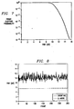
- the 15.5 dB Showtime PAR was for an approximate frame clipping probability of 10 -6 , as shown in Figure 7.
- Figure 8 shows the PAR of the mapped zero signal relative to a Showtime signal over 300 frames.
- Figure 9 illustrates mapping of a zero input after optimization for a 26 AWG 12 kft channel.
- a method for mapping an all zero bit sequence to a DMT symbol with low PAR is presented. Since this mapping can be used with all bit sequences, the transmitter does not need to transmit a special symbol for Q-mode. Thus, the operation of Q-mode is transparent to the physical layer.
- a method for determining the mapping was given which takes the bit loading and AFE into account, allowing the PAR to be optimized for the observed channel conditions.
Landscapes
- Engineering & Computer Science (AREA)
- Computer Networks & Wireless Communication (AREA)
- Signal Processing (AREA)
- Digital Transmission Methods That Use Modulated Carrier Waves (AREA)
- Cable Transmission Systems, Equalization Of Radio And Reduction Of Echo (AREA)
Applications Claiming Priority (4)
| Application Number | Priority Date | Filing Date | Title |
|---|---|---|---|
| US28212801P | 2001-04-06 | 2001-04-06 | |
| US28913001P | 2001-05-08 | 2001-05-08 | |
| US289130 | 2002-11-06 | ||
| US282128 | 2005-11-18 |
Publications (2)
| Publication Number | Publication Date |
|---|---|
| EP1248426A2 true EP1248426A2 (de) | 2002-10-09 |
| EP1248426A3 EP1248426A3 (de) | 2006-05-17 |
Family
ID=26961261
Family Applications (1)
| Application Number | Title | Priority Date | Filing Date |
|---|---|---|---|
| EP02100345A Withdrawn EP1248426A3 (de) | 2001-04-06 | 2002-04-05 | Architektur eines ruhenden Modus für niedrige Spitzendurchschnittsleistungsverhältnisse sowie Signaldesignmethode für DMT-Modems |
Country Status (2)
| Country | Link |
|---|---|
| US (1) | US20030039306A1 (de) |
| EP (1) | EP1248426A3 (de) |
Cited By (4)
| Publication number | Priority date | Publication date | Assignee | Title |
|---|---|---|---|---|
| WO2004082230A1 (en) * | 2003-03-14 | 2004-09-23 | Upzide Labs Ab | Arrangements and methods for a digital communication system |
| EP1998461A1 (de) * | 2007-05-29 | 2008-12-03 | Nokia Siemens Networks Oy | Verfahren und Vorrichtung zur Verarbeitung von Daten und Kommunikationssystem mit einer derartigen Vorrichtung |
| US20100115295A1 (en) * | 2008-11-05 | 2010-05-06 | Wael William Diab | Method And System For Energy Efficient Communication Among One Or More Interfaces In A Communication Path |
| WO2016197979A1 (en) * | 2015-06-12 | 2016-12-15 | Huawei Technologies Co., Ltd. | Trellis shaping on ldpc-coded modulation dmt systems |
Families Citing this family (12)
| Publication number | Priority date | Publication date | Assignee | Title |
|---|---|---|---|---|
| US20060203927A1 (en) * | 2001-03-27 | 2006-09-14 | Aware, Inc. | Systems and methods for implementing receiver transparent Q-mode |
| KR20040004562A (ko) * | 2001-03-27 | 2004-01-13 | 어웨어, 인크. | 수신기 투과성 q-모드 |
| US7010028B2 (en) * | 2001-07-16 | 2006-03-07 | Broadcom Corporation | System and method for rapid generation of low par Q-mode signals |
| US7403569B2 (en) * | 2004-02-03 | 2008-07-22 | Texas Instruments Incorporated | Efficient low-power mode for multicarrier communications |
| US7414958B2 (en) * | 2004-03-29 | 2008-08-19 | Stmicroelectronics Ltd. | Efficient tone ordering for multitone transmission |
| US8355457B2 (en) * | 2004-10-26 | 2013-01-15 | Lsi Corporation | Correction-calculation algorithm for estimation of the signal to noise ratio in high bit rate DMT modulation |
| EP1853018B1 (de) | 2006-05-03 | 2014-03-05 | Industrial Technology Research Institute | Kodierung und Dekodierung für Mehrträgersignale |
| US9425856B2 (en) * | 2014-01-17 | 2016-08-23 | Broadcom Corporation | System and method for multi-dimensional modulation schemes with high noise immunity and low emission idle signaling for automotive area networks |
| US10098813B2 (en) | 2014-09-03 | 2018-10-16 | Sun Pharmaceutical Industries Limited | Perfusion dosage form |
| US10700812B2 (en) | 2015-05-14 | 2020-06-30 | Sony Corporation | Device, method, and program |
| ES2968415T3 (es) | 2016-02-09 | 2024-05-09 | Sun Pharmaceutical Ind Ltd | Sistema de perfusión |
| US10862646B2 (en) * | 2017-07-11 | 2020-12-08 | Nokia Technologies Oy | Polar coded broadcast channel |
Family Cites Families (8)
| Publication number | Priority date | Publication date | Assignee | Title |
|---|---|---|---|---|
| EP0064119B1 (de) * | 1981-04-30 | 1985-08-28 | International Business Machines Corporation | Sprachkodierungsverfahren und Einrichtung zur Durchführung des Verfahrens |
| US6201830B1 (en) * | 1997-06-11 | 2001-03-13 | Texas Instruments Incorporated | Low computation idle transmission method for DSL modems |
| US6052411A (en) * | 1998-04-06 | 2000-04-18 | 3Com Corporation | Idle mode for digital subscriber line |
| US6853632B1 (en) * | 1998-09-24 | 2005-02-08 | Amit Verma | Technique for peak power to average power ratio reduction in multicarrier communication systems |
| US6810502B2 (en) * | 2000-01-28 | 2004-10-26 | Conexant Systems, Inc. | Iteractive decoder employing multiple external code error checks to lower the error floor |
| US7003044B2 (en) * | 2000-02-01 | 2006-02-21 | Sasken Communication Technologies Ltd. | Method for allocating bits and power in multi-carrier communication system |
| US6839389B2 (en) * | 2000-03-13 | 2005-01-04 | Pri Research & Development Corp. | Digital quadrature demodulation and decimation without multipliers |
| KR20040004562A (ko) * | 2001-03-27 | 2004-01-13 | 어웨어, 인크. | 수신기 투과성 q-모드 |
-
2002
- 2002-03-27 US US10/107,519 patent/US20030039306A1/en not_active Abandoned
- 2002-04-05 EP EP02100345A patent/EP1248426A3/de not_active Withdrawn
Cited By (11)
| Publication number | Priority date | Publication date | Assignee | Title |
|---|---|---|---|---|
| WO2004082230A1 (en) * | 2003-03-14 | 2004-09-23 | Upzide Labs Ab | Arrangements and methods for a digital communication system |
| US7672392B2 (en) | 2003-03-14 | 2010-03-02 | Ericsson Ab | Arrangements and methods for a digital communication system |
| EP1998461A1 (de) * | 2007-05-29 | 2008-12-03 | Nokia Siemens Networks Oy | Verfahren und Vorrichtung zur Verarbeitung von Daten und Kommunikationssystem mit einer derartigen Vorrichtung |
| WO2008145479A1 (en) * | 2007-05-29 | 2008-12-04 | Nokia Siemens Networks Oy | Method and device for processing data and communication system comprising such device |
| US9048925B2 (en) | 2007-05-29 | 2015-06-02 | Adtran GmbH | Method and device for processing data and communication system comprising such device |
| US20100115295A1 (en) * | 2008-11-05 | 2010-05-06 | Wael William Diab | Method And System For Energy Efficient Communication Among One Or More Interfaces In A Communication Path |
| US8356190B2 (en) * | 2008-11-05 | 2013-01-15 | Broadcom Corporation | Method and system for energy efficient communication among one or more interfaces in a communication path |
| WO2016197979A1 (en) * | 2015-06-12 | 2016-12-15 | Huawei Technologies Co., Ltd. | Trellis shaping on ldpc-coded modulation dmt systems |
| CN107431735A (zh) * | 2015-06-12 | 2017-12-01 | 华为技术有限公司 | Ldpc编码调制dmt系统上的格栅整形 |
| US10181973B2 (en) | 2015-06-12 | 2019-01-15 | Futurewei Technologies, Inc. | Trellis shaping on LDPC-coded modulation DMT systems |
| CN107431735B (zh) * | 2015-06-12 | 2019-10-22 | 华为技术有限公司 | 一种生成星座映射的方法和装置 |
Also Published As
| Publication number | Publication date |
|---|---|
| US20030039306A1 (en) | 2003-02-27 |
| EP1248426A3 (de) | 2006-05-17 |
Similar Documents
| Publication | Publication Date | Title |
|---|---|---|
| US20030039306A1 (en) | Low peak-to-average ratio quiescent mode architecture and signal design method for DMT modems | |
| US6925128B2 (en) | Method and apparatus for reducing a peak-to-average power ratio in an orthogonal frequency division multiplex signal | |
| CN101518013B (zh) | 降低单载波和scbt通信系统中的papr的方法和系统 | |
| US7013421B2 (en) | Trellis interleaver and feedback precoder | |
| US20080137767A1 (en) | Ofdm clipping using sidebands and up-sampling | |
| US20010022777A1 (en) | Peak to average power ratio reduction in communication systems | |
| US6674768B1 (en) | Data transmission device and data transmission method capable of minimizing delay of fast data | |
| US20050195907A1 (en) | VDSL protocol with low power mode | |
| US6081502A (en) | Method and apparatus for reducing probability of clipping | |
| EP0981883A1 (de) | Initialisierungsprotokoll für sende-empfänger in einem diskret-mehrton-system (dmt) | |
| JPH11313044A (ja) | マルチキャリヤデ―タ通信システム内に広範囲のユ―ザデ―タ速度を設ける方法および装置 | |
| JP2002513521A (ja) | 多重搬送波伝送システムの改良 | |
| JP2002314502A (ja) | デジタル信号の変調方法及び離散的なマルチトーン被変調信号を送信するトランシーバ | |
| US6823002B1 (en) | Linear block interleaver for discrete multi-tone modulation | |
| Kou et al. | New peak-to-average power-ratio reduction algorithms for multicarrier communications | |
| CN100484116C (zh) | Ofdm通信系统及降低峰均功率比的方法 | |
| US7403569B2 (en) | Efficient low-power mode for multicarrier communications | |
| CN111884761A (zh) | 一种用于单载波频域均衡系统发送端的数据发送方法 | |
| US7133444B2 (en) | Combined equalization for DMT-based modem receiver | |
| US6658024B1 (en) | Data transmission device and data transmission method capable of minimizing delay of fast data both in normal conditions and noisy conditions | |
| US20180359120A1 (en) | Precompensation of interference induced by an ofdm/oqam modulation that is faster than nyquist | |
| JP4918139B2 (ja) | 通信システムにおけるピーク対平均電力比低減のための方法 | |
| Feig | Practical aspects of DFT-based frequency division multiplexing for data transmission | |
| US6891896B1 (en) | Embedded signal constellations | |
| US7254180B1 (en) | Discrete multitone transmission systems |
Legal Events
| Date | Code | Title | Description |
|---|---|---|---|
| PUAI | Public reference made under article 153(3) epc to a published international application that has entered the european phase |
Free format text: ORIGINAL CODE: 0009012 |
|
| AK | Designated contracting states |
Kind code of ref document: A2 Designated state(s): AT BE CH CY DE DK ES FI FR GB GR IE IT LI LU MC NL PT SE TR |
|
| AX | Request for extension of the european patent |
Free format text: AL;LT;LV;MK;RO;SI |
|
| PUAL | Search report despatched |
Free format text: ORIGINAL CODE: 0009013 |
|
| AK | Designated contracting states |
Kind code of ref document: A3 Designated state(s): AT BE CH CY DE DK ES FI FR GB GR IE IT LI LU MC NL PT SE TR |
|
| AX | Request for extension of the european patent |
Extension state: AL LT LV MK RO SI |
|
| AKX | Designation fees paid | ||
| REG | Reference to a national code |
Ref country code: DE Ref legal event code: 8566 |
|
| STAA | Information on the status of an ep patent application or granted ep patent |
Free format text: STATUS: THE APPLICATION IS DEEMED TO BE WITHDRAWN |
|
| 18D | Application deemed to be withdrawn |
Effective date: 20061118 |