EP1248500A2 - Torche de soudage - Google Patents
Torche de soudage Download PDFInfo
- Publication number
- EP1248500A2 EP1248500A2 EP02014132A EP02014132A EP1248500A2 EP 1248500 A2 EP1248500 A2 EP 1248500A2 EP 02014132 A EP02014132 A EP 02014132A EP 02014132 A EP02014132 A EP 02014132A EP 1248500 A2 EP1248500 A2 EP 1248500A2
- Authority
- EP
- European Patent Office
- Prior art keywords
- nozzle element
- gas
- nozzle
- axially
- electrode
- Prior art date
- Legal status (The legal status is an assumption and is not a legal conclusion. Google has not performed a legal analysis and makes no representation as to the accuracy of the status listed.)
- Withdrawn
Links
Images


Classifications
-
- H—ELECTRICITY
- H05—ELECTRIC TECHNIQUES NOT OTHERWISE PROVIDED FOR
- H05H—PLASMA TECHNIQUE; PRODUCTION OF ACCELERATED ELECTRICALLY-CHARGED PARTICLES OR OF NEUTRONS; PRODUCTION OR ACCELERATION OF NEUTRAL MOLECULAR OR ATOMIC BEAMS
- H05H1/00—Generating plasma; Handling plasma
- H05H1/24—Generating plasma
- H05H1/26—Plasma torches
- H05H1/32—Plasma torches using an arc
- H05H1/34—Details, e.g. electrodes, nozzles
-
- H—ELECTRICITY
- H05—ELECTRIC TECHNIQUES NOT OTHERWISE PROVIDED FOR
- H05H—PLASMA TECHNIQUE; PRODUCTION OF ACCELERATED ELECTRICALLY-CHARGED PARTICLES OR OF NEUTRONS; PRODUCTION OR ACCELERATION OF NEUTRAL MOLECULAR OR ATOMIC BEAMS
- H05H1/00—Generating plasma; Handling plasma
- H05H1/24—Generating plasma
- H05H1/26—Plasma torches
- H05H1/32—Plasma torches using an arc
- H05H1/34—Details, e.g. electrodes, nozzles
- H05H1/3442—Cathodes with inserted tip
-
- H—ELECTRICITY
- H05—ELECTRIC TECHNIQUES NOT OTHERWISE PROVIDED FOR
- H05H—PLASMA TECHNIQUE; PRODUCTION OF ACCELERATED ELECTRICALLY-CHARGED PARTICLES OR OF NEUTRONS; PRODUCTION OR ACCELERATION OF NEUTRAL MOLECULAR OR ATOMIC BEAMS
- H05H1/00—Generating plasma; Handling plasma
- H05H1/24—Generating plasma
- H05H1/26—Plasma torches
- H05H1/32—Plasma torches using an arc
- H05H1/34—Details, e.g. electrodes, nozzles
- H05H1/3468—Vortex generators
-
- H—ELECTRICITY
- H05—ELECTRIC TECHNIQUES NOT OTHERWISE PROVIDED FOR
- H05H—PLASMA TECHNIQUE; PRODUCTION OF ACCELERATED ELECTRICALLY-CHARGED PARTICLES OR OF NEUTRONS; PRODUCTION OR ACCELERATION OF NEUTRAL MOLECULAR OR ATOMIC BEAMS
- H05H1/00—Generating plasma; Handling plasma
- H05H1/24—Generating plasma
- H05H1/26—Plasma torches
- H05H1/32—Plasma torches using an arc
- H05H1/34—Details, e.g. electrodes, nozzles
- H05H1/3478—Geometrical details
-
- H—ELECTRICITY
- H05—ELECTRIC TECHNIQUES NOT OTHERWISE PROVIDED FOR
- H05H—PLASMA TECHNIQUE; PRODUCTION OF ACCELERATED ELECTRICALLY-CHARGED PARTICLES OR OF NEUTRONS; PRODUCTION OR ACCELERATION OF NEUTRAL MOLECULAR OR ATOMIC BEAMS
- H05H1/00—Generating plasma; Handling plasma
- H05H1/24—Generating plasma
- H05H1/26—Plasma torches
- H05H1/32—Plasma torches using an arc
- H05H1/34—Details, e.g. electrodes, nozzles
- H05H1/3489—Means for contact starting
Definitions
- the present invention relates to a plasma torch or Plasma arc welding torch and a nozzle element suitable for this and relates in particular to improvements in the flow of gas for cooling and operating the torch.
- Plasma arc welding torches usually have an electrode and a nozzle element in which the working tip of the Electrode is supported so that the end face of the electrode a head wall of the nozzle element having a plasma outlet opening opposite.
- the electrode and the nozzle element can be relative to each other between a position in which the Electrode touches the head wall of the nozzle element, and a position in which the electrode is a working distance from the head wall is spaced, movable so that a pilot arc can be generated when the electrode is off the head wall moved away to their working position.
- the Electrode and the nozzle element also stationary relative to each other be, the welding torch then using high frequency or other known starting process is ignited.
- the head wall and the head surface the electrode a gas space, which a plasma or arc gas is supplied and from which a plasma jet through the outlet opening emerges when between the electrode and the nozzle element an arc current flows.
- a plasma or arc gas is supplied and from which a plasma jet through the outlet opening emerges when between the electrode and the nozzle element an arc current flows.
- the plasma gas upstream of the gas space To give swirl movement which serves cooling purposes on the one hand, on the other hand has the purpose of bundling the ejected plasma jet to keep in line with the axis of the electrode. Through a such swirl can produce a good quality plasma arc become. It also improves the cutting speed and thus the profitability and efficiency of the performed work and is generally in the operation of the Welding torch helpful. It is also known in welding torches with fixed nozzle and electrode arrangement gas with swirl To face inward on the end faces of the electrode to remove erosion deposits to remove or even from the nozzle element not to let it occur and thus increase its lifespan increase.
- the slackening of the twist motion is to explain that the gas as soon as it leaves the passage or exits the passages which give the gas the swirl movement, to and through the gas space Inner surfaces of the nozzle element to the plasma jet outlet opening moves that are evenly shaped and therefore unsuitable, the maintain initial swirl motion. Also learns the swirling gas usually has a pressure drop when it comes out of the Passage or the passages in which the swirling exits is generated, with such a pressure loss to weaken of the swirl contributes to the swirl flow.
- the object of the invention is the flow behavior of the gas relative to the electrode and nozzle element of a plasma torch to improve.
- a nozzle element be created for a plasma torch with an arrangement which gives the plasma gas a twist when it goes to and through the outlet opening one between the electrode and the nozzle member arranged gas space flows.
- a plasma arc welding torch is used with an improved nozzle and Electrode arrangement for controlling the plasma gas flow created, to achieve the best possible cooling and one as possible straight plasma jet and good plasma gas shielding to get for the beam.
- a plasma torch with nozzle and Electrode elements created to generate a pilot arc are displaceable relative to each other and so in contact can be brought or separated from each other, the Burner has improved gas flow control, resulting in a Gas bias of the components both for bringing them into contact as well as optimized for their separation.
- the invention turns into a plasma welding torch indicated with a nozzle and electrode arrangement, for an improved flow characteristic of the plasma gas ensures and the high quality of the arc beam and thus the work performed as well as a special one high efficiency and low operating costs of the welding torch can be achieved.
- the present invention provides an improved nozzle element and electrode assembly for a plasma arc welding torch created in which the aforementioned and others, disadvantages inherent in the control of gas flow be reduced to a minimum or completely overcome.
- the head wall of the nozzle element with the outlet opening for the plasma jet with a guide arrangement provided that ensures that the extent of the Gas chamber entering the plasma gas radially along the head wall Swirl is led to the outlet opening, the gas up to Entrance of the plasma jet outlet is swirled to it to press or narrow radially into a beam, which is special is straight and high stability against lateral deflection Has.
- the gas flow is only swirled in the direction of flow behind the working tip of the electrode so that it has no erosive influence on them and therefore the service life the electrode is not shortened.
- the gas the swirl movement is given by the inside of the head wall of the nozzle element with several, spaced in the circumferential direction, arc-shaped ribs is provided, between which curved, approximately spiral from the outer edge of the gas chamber to Exhaust opening extending channels are formed which the plasma gas give the swirl movement where the plasma arc or beam is generated.
- the plasma gas can reach the tip of the electrode, if the latter hits the ribs, the available force to push the electrode back out of contact with the nozzle element to increase.
- one of which is pressurized by means of a solenoid valve controlled piston arrangement is provided and actuated to bring the electrode into contact with the nozzle element the contact force between the working tip of the electrode and the nozzle element due to the smaller contact area between the electrode and the nozzle element with the same Gas pressure will increase.
- the gas pressure can also be reduced that is required to have a good electrical Contact between the electrode and the nozzle element too create compared to the one that is then required if an electrode against a smooth inner surface of the nozzle element encounters.
- the nozzle element is on a welding torch body together with a coaxial sleeve arrangement mounted, which forms an annular cooling cavity, through which a portion of the plasma gas can flow, and preferably a conical gas protection jacket around the out of the gas space forms in the interior of the nozzle element emerging plasma jet.
- the coaxial sleeve elements preferably clamp axially Flange arrangement on the outer edge of the nozzle element near one its ends and the flange and the corresponding end of the Nozzle element with one through the welding torch body associated with swirling gas, part of the gas flows outward and over the flange assembly while the remaining part of the gas inside the nozzle element and along the electrode flows to the gas space.
- the nozzle element instructs its outer edge has an axially extending recess in the flow direction behind the flange arrangement, through which the Flange arrangement flowing gas radially outwards and axially to the outside is deflected in front of the nozzle element and thus a protective gas jacket around the plasma jet emerging from the gas space.
- the flange assembly is in with the annular cooling cavity Connection and provides, together with the recess downstream, for a simply constructed nozzle element in which the flow part of the plasma gas is controlled to cool achieve and form a conical protective gas jacket, while the remaining part of the gas between the nozzle element and the electrode is steered to get into the gas space and to generate a plasma beam there.
- the nozzle element Preferably that comes between the electrode and the nozzle element and towards the gas space flowing plasma gas from a swirl arrangement in the direction of flow of the gas is arranged in front of the nozzle element.
- the structure of the nozzle element allows an external flow in the Cooling space in and along the outside of the nozzle element and thereby creates a preferably conical gas shield regardless of the plasma gas in the gas space, which causes its swirl movement is issued immediately at the point where the plasma jet arises.
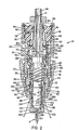
- FIG. 1 and 2 show an arc plasma welding torch 10 with a body part 12 aligned coaxially to an axis A, that a coaxially arranged nozzle element, an electrode and has an arrangement for electrode displacement, the following will be described in detail.
- the information “below” and “above” are accordingly the vertical orientation of the welding torch 10 in FIG. 1 and 2 used.
- the body part 12 has a lower, provided with an internal thread 14 and an external thread 16 The End.
- a swirl ring construction arranged, a sleeve 18 made of insulating material and has a mounting sleeve 20 and with one arranged on the sleeve 18 External thread 22 in the internal thread 16 on the body part 12 is screwed in.
- the insulating sleeve 18 is on its inner wall with a plurality of radial passage openings 24 and with an o-ring seal 26 provided in an extending on the circumference of the sleeve Ring groove is added.
- the mounting sleeve 20 has at its lower end an end face 28 transverse to axis A.
- a nozzle element 34 is mounted at the lower end of the body part 12 at the lower end of the body part 12 at the lower end of the body part 12 is by means of a mounting sleeve or a shield sleeve 36.
- the shield sleeve 36 has an internal thread at its upper section 38, which cooperates with the external thread 14 on the body part 12.
- the nozzle element 34 which will be described in more detail below has an intermediate section with a mounting flange located between the upper and lower ends 40 on that between the end face 28 of the mounting sleeve 20 and one formed at the lower end of the end sleeve 36 by a flange 42 and shoulder extending radially into the sleeve 41 is clamped. As can best be seen in FIG.
- the inside of the shielding sleeve 36 has a conical surface 44, which extends from the shoulder 41 to the internal thread 38 and that radially from the cone wall portion 30 and the ribs 32 the mounting sleeve 20 is spaced and thus a cavity 46 forms, the meaning of which will be explained below.
- Supported electrode 48 which is relative to the nozzle element 34 is displaceable.
- the electrode 48 has an outer cylindrical one Working tip 50 received in the nozzle member 34 and is at the bottom near her End face 52 an insert 54 made of hafnium, zirconium, tungsten or some other suitable material that is used together with the nozzle element when operating the welding torch generate a plasma arc, as is the case with plasma torches is known.
- the electrode 48 is above the working tip 50 with a Provided gas swirl section, the helical swirl grooves 56th has and received in the sleeve 18 of the swirl ring construction is that the grooves 56 together with the sleeve wall are preferred form closed channels.
- the top end of the electrode 48 is provided with a head 58.
- the one between the swirl grooves 56 and the sleeve 18 formed, helical channels Inlet gaps located below and near head 58 the passage openings 24 are arranged in the sleeve 18.
- the the lower outlet gaps of the channels are above the working tip 50 and are close to each other End faces of the nozzle element 34 and sleeve 18 are arranged.
- the welding torch 10 also has a piston-cylinder arrangement , with the help of the electrode 48 relative to the welding torch body 12 and thus also axially displaceable to the nozzle element 34 is.
- This is at the upper end of the welding torch body 12 a cylinder element 6.0 with a head part 62 on the top End of the body 12 and provided with a sleeve part 64, the extends downward from the headboard 62 and with its lower one End the sleeve 18 of the swirl ring construction outside in Axial direction overlapped a bit.
- the head part 62 bumps with its lower end on a shoulder 66 in the welding torch body 12 and is at the top with a locking ring 68 in Welding torch body 12 held.
- the outer surface of the sleeve section 64 of the cylinder element 60 is with several axially extending Provide recesses 70 which are distributed over the circumference are spaced from each other. Also in the sleeve section a plurality of passage openings 73 are provided, the radially starting from some or all of the recesses 72 extend through the sleeve portion 64.
- ventilation openings 74 are arranged, which open into an annular channel through an opening 78 in the welding torch body 12 in connection with ambient air is.
- the ventilation openings are between two 0-rings 80 arranged in associated, in the outer circumference of the head section 62 trained grooves sit and the head section against seal the inside surface of the torch body 12 if the cylinder element is mounted in this.
- the piston-cylinder arrangement of the welding torch 10 also has a piston element 82 with a head 84, the one has annular sealing ring 86.
- the lower end 88 of the piston member 82 faces the head 58 of the electrode while it is at the top in Form a tube 90 protrudes from the burner.
- the piston 82 is received in the cylinder element 60 and axially in this reciprocable; for this purpose the head 84 of the piston is in the sleeve section 64 of the cylinder element 60 added, the lower piston end 88 abuts the upper end 58 of the electrode.
- the piston 82 is supported by a compression spring 92 from that shown in FIG. 2 Biased position down. The piston 82 is in the position shown in Fig.
- Plasma gas used as cooling and working gas is therefore in the welding torch body 12 supplied through the inlet 94, which as radial opening is formed in the welding torch body and itself near the upper ends of the recesses 70 in the sleeve portion 64 of the cylinder element 60 is located.
- the nozzle element 34 approximately tubular and forms a coaxial to the axis A aligned cylinder bore 100 which at the upper end 101 of the Nozzle element 34 is open and so is the working tip 50 of the lead electrode 48 can accommodate.
- the lower end of the cylinder bore is bounded by an end wall 102 arranged transversely to the axis A, in which a plasma arc outlet opening 104 is also coaxial to axis A is provided.
- the mounting flange 40 has one upper and a lower flange side 106 and 108 and one Outside edge and is on with the circumference at regular intervals distributed, V-shaped recesses 110 provided are open to the outside edge.
- first cylindrical section 112 Below the lower one Flange side 108 of flange 40 has nozzle element 34 first cylindrical section 112, an adjoining, flared portion 114 and a second cylindrical section 116, which has a larger diameter has as the first cylindrical portion 112, so that the conical section of the smaller diameter of the first cylinder section to the larger diameter of the second cylinder section expanded accordingly.
- Each of the recesses 110 on the flange 40 has one opposite first cylinder section 112 radially further outward inner surface 118, i.e. that of the inner surfaces of the recesses 110 defined diameter is larger than the diameter of the first Cylinder section.
- the upper end of the nozzle element 34 is in the Area between the upper flange side 106 and the upper end 101 of the nozzle element is provided with a plurality of axial grooves 120.
- the Number of axial grooves 120 corresponds to the number of recesses 110, wherein each groove 120 is assigned a recess 110 and Groove and associated recess are arranged so that each other the groove base 122 of each groove is coplanar with the radially inner one Surface 118 of the associated recess 110 is.
- the cylinder space 100 of the nozzle element 34 is on its circumference through which from the upper end 101 of the nozzle element to End wall 102 extending cylinder surface 124 delimited.
- the End wall 102 has an inner top surface 126 that is approximately orthogonal to axis A and in the embodiment shown between peripheral surface 124 and outlet opening 104 slightly is inclined.
- the peripheral surface 124 goes under one Radius in the top 126 of the end wall 102.
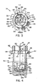
- On the Top side 126 of end wall 102 is a plurality of swirl ribs 130 provided at an even distance around axis A. are arranged and approximately spiral from the peripheral surface 124 extend radially inward towards the outlet opening 104. In the illustrated embodiment, there are six of them Swirl ribs provided. As can be seen particularly clearly from FIG.
- each of these ribs has an outer and an inner curved Side wall 132 and 134, which are approximately parallel and in Are spaced from each other, the radial thickness of a Rib sets.
- the arrangement is such that the side walls 132 and 134 a radius of curvature R1 or R2 by one have reference point 136 to the side of axis A.
- the reference point 136 lies on a first reference line 137, with a second, orthogonal reference line 139 intersects at a point that is opposite to the axis A.
- Piece is radially offset.
- the reference lines 137, 139 and reference points 136 as centers of curvature for the radii R1 and R2 of adjacent ribs evenly distributed and have an angular distance that is 360 °, divided by the number of ribs. Accordingly would be the reference lines (not shown) and the reference point for the dot-dash line 130 shown in FIG. 5 60 ° clockwise from reference line 137 and the Reference point 136 is offset, which is shown in Fig. 5 for the solid shown (left) rib are shown.
- the radius of curvature corresponds the outer ends 140 of the ribs the inner radius of the cylinder wall 124 of the cylinder bore 100.
- FIG. 6 shows that the ribs 130 have an upper side, the radially outer-res, a bit above the top 126 of the end wall 102 End has an arc section 144 that has a harmonic Forms transition to the inner wall 124 of the cylinder opening 100.
- the Thickness of the ribs in the axial direction to the radially inner end back which in turn has a second arc section 146, which has a practically stepless transition to the top 126 the end wall ensures.
- the top 142 is preferred between their radially inner and radially outer ends convexly curved, which creates a particularly good contact between Electrode and top of the fins when starting the welding torch is achieved.
- the channels are designed so that the gas on their Eject outlet openings in directions that are approximately tangent to Outlet opening 104 run.
- the trained between the ribs Channels ensure through their special design that the gas not only swirls when entering the outlet opening 104, but is also constricted radially, making a special straight (linear) plasma jet emerges from the welding torch.
- the inner diameter the cylinder opening 100 of the nozzle element 34 is approximately 8.636 mm and the inside top 126 of the end wall is about 15 ° inclined to a plane orthogonal to axis A.
- the diameter of the outlet opening 104 is in the exemplary embodiment shown about 1.07 mm, while the radii of curvature R1 and R2 at 3.175 and 2.54 mm, respectively, and the radii R3 and R4 at 1.78 or 4.32 mm.
- the reference point 136 is at a distance from Intersection of lines 137 and 139 of 1.93 mm, the Intersection of these two lines in turn by 0.1016 mm from the Axis A is spaced.
- the radius of curvature of the arcuate Sections 128, 144 and 146 between the inner and end faces, respectively 124, 126 of the nozzle and the outer and inner ends of the ribs 130 is 0.635 mm.
- Each rib is with a radius of 3.175 mm convexly curved on its upper side around a center of curvature, which is 5.26 mm from the axis to the side and 16.33 mm from the top 106 of the flange is removed.
- the electrode is shown in its working position, in which the working tip 50 is at a distance above the end wall 102 of the nozzle element 34 is located.
- electrode and nozzle element are arranged in a manner known per se, that they are connected to each other via a power source, so that a pilot arc was struck between these two components becomes and burns when the electrode is shown in Fig. 2 Position down in contact with the nozzle element 34 or its Swirl ribs 130 brought and then back into their in Fig. 2 shown position is withdrawn.
- the starting process is between the lower end face 52 of the working tip 50 of the electrode and the axially inner top 126 of the end wall 102 of the nozzle element 34 is a plasma gas space 150 formed, the one running around its outer edge, has annular inlet 152 which passes through the annular gap between the inner wall 124 of the nozzle element and the peripheral surface the working tip 50 of the electrode 48 is fixed.
- the end face 52 of the Working tip 50 of the electrode 48 due to the compression spring 92 applied force on the ribs 130.
- a plasma gas is then passed through inlet 94 into the welding torch body 12 initiated and flows through the annular Gap between the body 12 and the cylinder sleeve 64 and axially along the recesses 70 through the passage openings 24 in the sleeve 18 of the swirl ring construction.
- After flowing through the Gas through the radial passage openings 24 acts on the gas pressure onto the underside of the head 58 of the electrode 48 and lifts it so against the bias of the spring 29 upwards in the in Fig. 2nd shown location.
- the gas continues to flow down along the top of the electrode and further through the swirl channels 56 to the lower end of the sleeve 18, where part of the gas with swirl into the annular passage between the inner wall 124 of the nozzle element and outside of the working tip 50 of the electrode flows and from there via an edge entry 152 into the gas space 50 arrives.
- the plasma gas then continues to flow approximately in a spiral inwards in the formed between adjacent ribs 130 Channels, from which it is approximately tangential to the outlet ends Edge of the outlet opening 104 emerges.
- the gas leaves the opening 104 thereby with a twist.
- the gas flows at his Entry 152 into the gas space 150 and radially through it to the outlet opening 104 and in its passage through the between the ribs 130 formed channels 148 and through the curved Sections 144 and 128 near entrance 152 due to the smooth transitions and radii practically without turbulence and there will be a particularly good flow transition between the axial-helical course along the working tip 50 the electrode 48 and the spiral, radially inward Flow in channels 148 along ribs 130 in Direction towards the outlet opening 104 reached.
- the design of the transition flow also has a special one Advantage that the direction of the swirl flow around the working tip 52 of the electrode around in the flow direction before Chamber 150 of the direction of flow of gas through channels 148 between the ribs, which also leads to the fact that a transition flow with very little or no flow Turbulence is developing.
- the special design of the nozzle element 34 has during operation the welding torch also has special advantages in direction control of the partial flow of the plasma gas provided for cooling.
- Another part of the plasma gas flowing through the grooves 120 passes radially outward from the recesses 110 into the annular gap between the surfaces 30 and 44 of the mounting ring or the shield sleeve 36 and the cooling fins 32 into the cavity 46, causing the components of the welding torch in this area be chilled well.
- the invention is not based on that shown and described Embodiment limited, but there are many Changes and additions without going beyond the scope of the invention leave.
- the invention is also possible to be used in such a welding torch where the nozzle and Electrode not slidably arranged to each other, but are stationary, in which case the burner is not moved the electrode in the nozzle element is started, but one appropriate electrical (radio frequency) circuit use place.
- the swirl of the gas can also be at its own Flow generated over the end face of the nozzle element be without the previously taken in the direction of flow of the gas Arrangement provided with the helical channels becomes.
- This swirl of the gas upstream can also be generated differently be, for example, that the gas is not through one radial, but one or more tangentially arranged Inlet openings 94 is supplied.
Landscapes
- Physics & Mathematics (AREA)
- Engineering & Computer Science (AREA)
- Plasma & Fusion (AREA)
- Spectroscopy & Molecular Physics (AREA)
- Geometry (AREA)
- Plasma Technology (AREA)
- Arc Welding In General (AREA)
Priority Applications (1)
| Application Number | Priority Date | Filing Date | Title |
|---|---|---|---|
| EP02014132A EP1248500A3 (fr) | 1998-05-26 | 1998-05-26 | Torche de soudage |
Applications Claiming Priority (2)
| Application Number | Priority Date | Filing Date | Title |
|---|---|---|---|
| EP98109489A EP0961527A1 (fr) | 1998-05-26 | 1998-05-26 | Torche de soudage |
| EP02014132A EP1248500A3 (fr) | 1998-05-26 | 1998-05-26 | Torche de soudage |
Related Parent Applications (2)
| Application Number | Title | Priority Date | Filing Date |
|---|---|---|---|
| EP98109489A Division EP0961527A1 (fr) | 1998-05-26 | 1998-05-26 | Torche de soudage |
| EP98109489.9 Division | 1998-05-26 |
Publications (2)
| Publication Number | Publication Date |
|---|---|
| EP1248500A2 true EP1248500A2 (fr) | 2002-10-09 |
| EP1248500A3 EP1248500A3 (fr) | 2004-04-21 |
Family
ID=8232000
Family Applications (2)
| Application Number | Title | Priority Date | Filing Date |
|---|---|---|---|
| EP02014132A Withdrawn EP1248500A3 (fr) | 1998-05-26 | 1998-05-26 | Torche de soudage |
| EP98109489A Withdrawn EP0961527A1 (fr) | 1998-05-26 | 1998-05-26 | Torche de soudage |
Family Applications After (1)
| Application Number | Title | Priority Date | Filing Date |
|---|---|---|---|
| EP98109489A Withdrawn EP0961527A1 (fr) | 1998-05-26 | 1998-05-26 | Torche de soudage |
Country Status (1)
| Country | Link |
|---|---|
| EP (2) | EP1248500A3 (fr) |
Cited By (2)
| Publication number | Priority date | Publication date | Assignee | Title |
|---|---|---|---|---|
| DE102009004968A1 (de) * | 2009-01-14 | 2010-07-29 | Reinhausen Plasma Gmbh | Srahlgeneator zur Erzeugung eines gebündelten Plasmastrahls |
| DE102009015510B4 (de) * | 2009-04-02 | 2012-09-27 | Reinhausen Plasma Gmbh | Verfahren und Strahlgenerator zur Erzeugung eines gebündelten Plasmastrahls |
Families Citing this family (4)
| Publication number | Priority date | Publication date | Assignee | Title |
|---|---|---|---|---|
| AT411972B (de) * | 2002-09-18 | 2004-08-26 | Fronius Int Gmbh | Brennerkopf für schweissbrenner sowie gasdüse, kontaktdüse und isolierhülse für einen solchen brennerkopf |
| US8350181B2 (en) | 2009-08-24 | 2013-01-08 | General Electric Company | Gas distribution ring assembly for plasma spray system |
| WO2018119389A1 (fr) * | 2016-12-23 | 2018-06-28 | Hypertherm, Inc. | Anneau à turbulence pour chalumeau à arc de plasma |
| US12159768B2 (en) * | 2019-03-25 | 2024-12-03 | Recarbon, Inc. | Controlling exhaust gas pressure of a plasma reactor for plasma stability |
Family Cites Families (8)
| Publication number | Priority date | Publication date | Assignee | Title |
|---|---|---|---|---|
| DE1271855B (de) * | 1967-08-26 | 1968-07-04 | Messer Griesheim Gmbh | Einrichtung zum Schneiden von Werkstuecken mittels eines Plasmastrahls |
| US3534388A (en) * | 1968-03-13 | 1970-10-13 | Hitachi Ltd | Plasma jet cutting process |
| US3813510A (en) * | 1972-02-04 | 1974-05-28 | Thermal Dynamics Corp | Electric arc torches |
| DD282349A7 (de) * | 1988-03-10 | 1990-09-12 | Finsterwalde Schweisstechnik | Plasmaschmelzschneidbrenner zum schneiden metallischer werkstoffe unter wasser |
| US5208448A (en) * | 1992-04-03 | 1993-05-04 | Esab Welding Products, Inc. | Plasma torch nozzle with improved cooling gas flow |
| US5451739A (en) * | 1994-08-19 | 1995-09-19 | Esab Group, Inc. | Electrode for plasma arc torch having channels to extend service life |
| US5726415A (en) * | 1996-04-16 | 1998-03-10 | The Lincoln Electric Company | Gas cooled plasma torch |
| US5951771A (en) * | 1996-09-30 | 1999-09-14 | Celestech, Inc. | Plasma jet system |
-
1998
- 1998-05-26 EP EP02014132A patent/EP1248500A3/fr not_active Withdrawn
- 1998-05-26 EP EP98109489A patent/EP0961527A1/fr not_active Withdrawn
Cited By (3)
| Publication number | Priority date | Publication date | Assignee | Title |
|---|---|---|---|---|
| DE102009004968A1 (de) * | 2009-01-14 | 2010-07-29 | Reinhausen Plasma Gmbh | Srahlgeneator zur Erzeugung eines gebündelten Plasmastrahls |
| DE102009004968B4 (de) * | 2009-01-14 | 2012-09-06 | Reinhausen Plasma Gmbh | Strahlgenerator zur Erzeugung eines gebündelten Plasmastrahls |
| DE102009015510B4 (de) * | 2009-04-02 | 2012-09-27 | Reinhausen Plasma Gmbh | Verfahren und Strahlgenerator zur Erzeugung eines gebündelten Plasmastrahls |
Also Published As
| Publication number | Publication date |
|---|---|
| EP0961527A1 (fr) | 1999-12-01 |
| EP1248500A3 (fr) | 2004-04-21 |
Similar Documents
| Publication | Publication Date | Title |
|---|---|---|
| DE69020885T2 (de) | Plasmabogenbrenner mit langer Düse. | |
| EP0741627B1 (fr) | Ensemble buse pour le decoupage au laser | |
| DE68907891T2 (de) | Vorrichtung und verfahren zur kühlung eines plasmabogens. | |
| DE69603673T2 (de) | Lichtbogenplasmabrenner mit Wassereinspritzung-Düsenanordnung | |
| DE69733783T2 (de) | Schweisselektrode | |
| DE69502836T2 (de) | Elektrodenstruktur für einen plasmabrenner | |
| DE212015000227U1 (de) | Plasmaschneidbrenner, Düse und Abschirmkappe | |
| DE102017202258B3 (de) | Düse zum Ausblasen von Druckluft | |
| EP4065309B1 (fr) | Buse pour dispositif d'usinage au laser et dispositif d'usinage au laser comprenant celle-ci | |
| EP3639631B1 (fr) | Électrodes pour torches à plasma refroidies par gaz et liquide, agencements desdites électrodes et d'un tube de refroidissement, et torche à plasma avec ces électrodes | |
| DE112015005926B4 (de) | Bearbeitungsdüse und Laserstrahl-Bearbeitungsvorrichtung | |
| DE102023108555A1 (de) | Düse für eine laserschneideinrichtung sowie verfahren zum laserschneiden eines werkstücks | |
| EP2625463B1 (fr) | Buse de découpe puissante pour la découpe en particulier de pièces d' uvre en acier | |
| EP3051928A1 (fr) | Torche à plasma | |
| EP1248500A2 (fr) | Torche de soudage | |
| EP2531320B1 (fr) | Buse pour un chalumeau de decoupe plasma, munie de rainures pour le refroidissement par liquide | |
| EP2457681A1 (fr) | Torche pour le soudage au gaz inerte et électrode tungstène et électrode destinée à être utilisée dans une telle torche | |
| CH648153A5 (de) | Druckgasschalter. | |
| DE2544402A1 (de) | Plasma-schneidbrenner | |
| EP2979030B1 (fr) | Buse de coupe de matériaux d'acier | |
| EP2723908B1 (fr) | Tête de lance d'une lance à oxygène | |
| DE3425633A1 (de) | Druckgasschalter | |
| EP0817228B1 (fr) | Sectionneur de puissance | |
| DE102019103659B4 (de) | Gasführung, Laserschneidkopf und Laserschneidmaschine | |
| EP2396799A1 (fr) | Appareillage de coupure |
Legal Events
| Date | Code | Title | Description |
|---|---|---|---|
| PUAI | Public reference made under article 153(3) epc to a published international application that has entered the european phase |
Free format text: ORIGINAL CODE: 0009012 |
|
| AC | Divisional application: reference to earlier application |
Ref document number: 961527 Country of ref document: EP |
|
| AK | Designated contracting states |
Kind code of ref document: A2 Designated state(s): AT BE DE DK ES FI FR GB IT NL SE |
|
| PUAL | Search report despatched |
Free format text: ORIGINAL CODE: 0009013 |
|
| AK | Designated contracting states |
Kind code of ref document: A3 Designated state(s): AT BE DE DK ES FI FR GB IT NL SE |
|
| 17P | Request for examination filed |
Effective date: 20040402 |
|
| AKX | Designation fees paid |
Designated state(s): AT BE DE DK ES FI FR GB IT NL SE |
|
| 17Q | First examination report despatched |
Effective date: 20060914 |
|
| GRAP | Despatch of communication of intention to grant a patent |
Free format text: ORIGINAL CODE: EPIDOSNIGR1 |
|
| RBV | Designated contracting states (corrected) |
Designated state(s): AT BE CH CY DE DK ES FI FR GB GR IE IT LI LU MC NL PT SE |
|
| STAA | Information on the status of an ep patent application or granted ep patent |
Free format text: STATUS: THE APPLICATION IS DEEMED TO BE WITHDRAWN |
|
| 18D | Application deemed to be withdrawn |
Effective date: 20080808 |