EP1248708B1 - Flurförderzeug zum heben und transportieren von mindestens einem fahrzeugrad - Google Patents
Flurförderzeug zum heben und transportieren von mindestens einem fahrzeugrad Download PDFInfo
- Publication number
- EP1248708B1 EP1248708B1 EP01903928A EP01903928A EP1248708B1 EP 1248708 B1 EP1248708 B1 EP 1248708B1 EP 01903928 A EP01903928 A EP 01903928A EP 01903928 A EP01903928 A EP 01903928A EP 1248708 B1 EP1248708 B1 EP 1248708B1
- Authority
- EP
- European Patent Office
- Prior art keywords
- attached
- cross
- telescopic
- members
- section
- Prior art date
- Legal status (The legal status is an assumption and is not a legal conclusion. Google has not performed a legal analysis and makes no representation as to the accuracy of the status listed.)
- Expired - Lifetime
Links
- 230000000712 assembly Effects 0.000 claims abstract description 19
- 238000000429 assembly Methods 0.000 claims abstract description 19
- 235000004443 Ricinus communis Nutrition 0.000 claims abstract description 8
- 240000000528 Ricinus communis Species 0.000 claims 1
- 238000005007 materials handling Methods 0.000 claims 1
- XEEYBQQBJWHFJM-UHFFFAOYSA-N Iron Chemical compound [Fe] XEEYBQQBJWHFJM-UHFFFAOYSA-N 0.000 description 6
- 238000006073 displacement reaction Methods 0.000 description 5
- 230000008878 coupling Effects 0.000 description 4
- 238000010168 coupling process Methods 0.000 description 4
- 238000005859 coupling reaction Methods 0.000 description 4
- 238000004519 manufacturing process Methods 0.000 description 4
- 229910052742 iron Inorganic materials 0.000 description 3
- 230000002457 bidirectional effect Effects 0.000 description 1
- 230000000903 blocking effect Effects 0.000 description 1
- 238000009434 installation Methods 0.000 description 1
- 238000011084 recovery Methods 0.000 description 1
- 238000003466 welding Methods 0.000 description 1
Images


Classifications
-
- B—PERFORMING OPERATIONS; TRANSPORTING
- B60—VEHICLES IN GENERAL
- B60B—VEHICLE WHEELS; CASTORS; AXLES FOR WHEELS OR CASTORS; INCREASING WHEEL ADHESION
- B60B29/00—Apparatus or tools for mounting or dismounting wheels
- B60B29/002—Apparatus or tools for mounting or dismounting wheels provided with a dolly
Definitions
- the field of the invention is that of handling vehicles mounted on wheels, such as in particular but not exclusively automobiles.
- handling involves moving a vehicle indoors or near a garage, a workshop (bodywork, mechanics, ...), an exhibition hall, parking, etc.
- a workshop bodywork, mechanics, ...), an exhibition hall, parking, etc.
- the invention relates to a handling trolley, of the type for lifting and supporting at least one wheel of a vehicle.
- a structure of handling trolley comprising two support assemblies, mounted on casters, and means for displacement of the two support assemblies relative to each other.
- Each of the support assemblies includes a telescopic element cooperating with the element telescopic from the other support assembly, and a cross member, attached (generally substantially perpendicular) on a free end of the element telescopic, and supporting at least one roller.
- a cart having such a structure may in particular take a rest position and a lifting position. In the rest position, the two telescopic elements are spaced from each other, so that the carriage can be placed under the wheel to be lifted, with the rollers positioned on the side on either side of the wheel. In the lifting position, the two telescopic elements are close together, so that the wheel is lifted and supported by the rollers.
- each cross member comprises a main body having a fold defining a flat part and an inclined part.
- the main body is fixed, by one of the ends of its flat part, at the free end of one of the telescopic elements.
- a swivel castor is mounted under each of the two ends of the flat part.
- support legs extend from both ends of the inclined portion so as to support an axis (substantially perpendicular to the telescopic elements) around which is rotatably mounted at least one roller.
- the means of displacement, of the two support assemblies with respect to each other include a ratchet tensioner acting on a strap, one end of which is fixed to a support (or axis) itself directly fixed to one of the two telescopic elements.
- each cross member comprises a linear central section having two ends from each of which extends a tapered end section.
- a swivel castor is mounted under each rung end section.
- the section linear center like the rung end sections, are portions of iron dish.
- One (so-called first) of the stepped end sections is welded on top from the free end of one of the two telescopic elements.
- the other (called second) stepped end section is removably attached to one end of the linear central section, via a coupling element.
- a roller is rotatably mounted around the linear central section, thanks to two rotation rings attached to both ends of this linear central section.
- the means of displacement, of the two support assemblies with respect to each other comprise a bidirectional rack, pedal operated.
- each cross member included in the first known carriage is relatively complex, and therefore quite difficult to manufacture and assemble. Indeed, we reminds that each cross member includes a main body (with its part plane and its inclined part), as well as two support legs of an axis on which a roller is rotatably mounted.
- the cross members included in the second known carriage are simpler. Indeed, the rollers are mounted in rotation directly around the central sections linear. However, with these cross members, the mounting of the rollers is not easy because it requires the prior disassembly of one of the two end sections in rung (ie that which is not attached to one of the telescopic elements). We recalls that the rung end section to be removed is removably attached to one end of the linear central section, via a coupling.
- the assembly of the rollers also requires the installation of two rings of rotation, at the two ends of each linear central section.
- each roller on two rotation rings causes a rapid wear of the internal wall of the roller, and especially of the two rings, and therefore results in more frequent changes to these items.
- the cross members are welded to the telescopic elements.
- the carriage therefore has a general "U" shape, which does not facilitate its storage, nor its transport.
- the invention particularly aims to overcome these various drawbacks of the state of the art.
- one of the objectives of the present invention is to provide a handling trolley, having the above structure, but not having the disadvantages of the cross member elements of the first and second known carriages described above.
- the invention also aims to provide such a handling trolley whose cross members are not very complex, simple to manufacture and assemble, and little expensive.
- Another object of the invention is to provide such a handling trolley allowing easy assembly / disassembly of the rollers.
- Another object of the invention is to provide such a handling cart, the cross members have good resistance to forces.
- Yet another object of the invention is to provide such a cart handling can be stored and transported in a compact form.
- An additional objective of the invention is to provide such a carriage handling to limit wear on the rollers.
- a handling trolley of the type allowing lift and support at least one wheel of a vehicle, said carriage comprising two support assemblies, mounted on casters, and means for moving both support assemblies relative to each other, said carriage being able to take in particular a rest position and a lifting position, each of said support assemblies comprising a telescopic element, cooperating with the telescopic element of the other support assembly, and a cross member, fixed substantially perpendicularly on a free end of said telescopic element, and supporting at least one roller.
- each of said cross members comprises a section linear unit with a first free end and a second end at from which extends a stepped end section, at least one wheel being mounted under said stepped end section, at least one roller capable of being rotatably mounted around said linear central section.
- each of said transom elements is fixed to the free end of one of the telescopic elements by said first free end of said central linear section. At least one roulette is mounted under the free end of each of the telescopic elements.
- the general principle of the invention therefore consists in simplifying the structure of transom elements (direct mounting of the rollers on the linear central sections, but with only one end section in step for each cross member) and at fix some casters directly on the telescopic elements.
- said section from end to step is fixed with non-removable fixing means to the second end of said central linear section.
- the structure of the cross member does not include any coupling (unlike the case of the second known carriage).
- Each of said cross members is fixed with means removable fixing at the free end of one of the telescopic elements, by the first end of said central linear section.
- the trolley according to the invention can be stored and transported easily, under a compact shape (disassembled cross member, for example stored parallel to the telescopic elements).
- said removable fixing means comprise a sleeve and an associated locking element.
- the sleeves offer the advantage of have good resistance to stresses, while being simple in design and of use (especially during assembly / disassembly of the rollers).
- said removable fixing means are located under the free end of one of the telescopic elements.
- the telescopic elements of the trolley according to the invention can be further from the ground than those of the second known carriage.
- the rollers of the carriage according to the invention remain in revenge as close to the ground as those of the second known carriage.
- said linear central section of each of said cross members is a substantially cylindrical bar portion. So we avoid the use of rotation rings, and the wear of the inner wall of the rollers is limited (thanks to a rotation on an axis of suitable shape).
- said means for displacement of the two support assemblies relative to each other include a lifting strap and means of action on said lifting strap, so as to induce the passage of said carriage from the rest position to the lifting position.
- Said means of action on the lifting strap are fixed to one of said telescopic elements.
- said lifting strap has a first end fixed to said means of action on the lifting strap, and a second end fixed to an end support element, secured to one of said cross members.
- the end support member is not fixed directly to one of the telescopic elements, but is integral with one of the cross-member elements.
- said end support element is integral with that of said cross member which is not fixed to the telescopic member to which are fixed said means of action on the lifting strap.
- This first variant applies in particular to the production of a quick-lift trolley with a limited load.
- said end support element is integral with that of said cross members which is fixed to the telescopic element to which are fixed said means of action on the lifting strap.
- said strap has a haulage passing through an intermediate support element, integral with that of said cross member which is not attached to the telescopic member to which are attached said means of action on the lifting strap.
- the tension of the strap is therefore here indirect, by hauling, which allows halve the effort.
- This second variant applies in particular to the production of a slower lifting carriage but with a higher load.
- the intermediate support element is only present in the second variant (hauling). It will also be noted that in the case of this second variant, the end support element and the intermediate support element (located each in one of the two support sets) are not necessarily the same type. In other words, one can be a free end of linear central section, while the other can be a support piece.
- said means of action on said lifting strap include a ratchet tensioner. It is important to note that the ratchet tensioner is used not only to tension the lifting strap, but also to lift the wheel.
- the invention therefore relates to a handling trolley, of the type enabling lift and support at least one wheel of a vehicle.
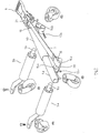
- the handling trolley comprises two support assemblies 1a, 1b, mounted on swivel casters 2a, 3a, 2b, 3b.
- a ratchet tensioner 6 and a strap 7 allow the displacement of the two support assemblies relative to each other (see explanation detailed below).
- Each of the support assemblies 1a, 1b comprises a telescopic element 4a, 4b, (fitting with the telescopic element of the other support assembly), and a cross member 5a, 5b fixed on a free end of the telescopic member (perpendicular to the latter).
- Each of the cross members 5a, 5b comprises a linear central section 8a, 8b having a first free end 9a, 9b and a second end 10a, 10b to which a section is fixed in a non-removable manner (for example by welding) from end to step 11a, 11b.
- Each of the cross members 5a, 5b is fixed by removably at the free end 13a, 13b of one of the telescopic elements 4a, 4b, by the first free end 9a, 9b of the central linear section 8a, 8b.
- This fixation removable, for example by blocking (using locking elements such as bolts 17a, 17b, pins, ...) of the first free end 9a, 9b of the section central linear 8a, 8b in a cylindrical sheath 14a, 14b integral (via two legs 15a, 16a, 15b, 16b) of the telescopic element concerned 4a, 4b, and located under the latter.
- a roller 12a, 12b is rotatably mounted around the linear central section 8a, 8b, the latter being a portion of a cylindrical bar (or axis).
- the left roller 12a is shown mounted, while right roller 12b is shown dismounted.
- the aforementioned removable fixing means 14a, 17a, 14b, 17b therefore make it possible to easily assemble and disassemble the rollers.
- a caster 2a, 2b is mounted under the flat part of each end section in step 11a, 11b.
- a caster 3a, 3b is mounted under the free end 13a, 13b of each of the telescopic elements 4a, 4b.
- the ratchet tensioner 6 is fixed to one of the telescopic elements 4b.
- the strap 7 has a first end 18 fixed to the ratchet tensioner 6, and a second end 19 fixed on an end support element 20.
- the latter 20 is integral, via a lug 15a (cf. below), of the cross member 5a "on the left" (that is to say one which is not fixed to the telescopic element 4b to which the ratchet tensioner 6) is fixed.
- the end support element 20 is an axis (or "part support ", such as a bolt) fixed on one of the legs 15a allowing itself to fix one of the cylindrical sleeves 14a under the free end 13a of one of the elements telescopic 4a.
- the end support element 20 can be the free end 9a of the linear central section 8a of the cross member 5a "of left".
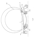
- Carriage is first placed in a rest position, so that it can be positioned under the wheel to be lifted, with the rollers touching the ground and positioned on either side of the wheel. Then, by operating the ratchet tensioner 6, the operator tightens the lifting strap 7, so as to bring the two telescopic elements 4a, 4b (which fit one into the other), until the rollers 12a, 12b are in contact with the wheel, and other of it. The carriage then arrives in the intermediate position. Finally, always in operating the ratchet tensioner 6, the operator reduces the length of the lifting strap 7 between the end support member 20 and the ratchet tensioner 6.
- the lifting strap 7 is wound around the axis forming the mandrel 21. This brings about an approximation (always by even larger) of the two telescopic elements 4a, 4b and therefore the horizontal approximation of the rollers. Note that the lifting is done with friction minimal due to the rotation of the two rollers on the cylindrical bars 8a, 8b. The carriage then arrives in the lifting position (see FIG. 4), in which the wheel 22 is raised and supported by the rollers 12a, 12b.
- the second embodiment differs from the first presented above essentially in that the tension of the strap 7 is not made directly, but indirectly. Indeed, we carry out a hauling of the strap consisting in making pass the strap around an intermediate support element 23, and fix the second end 19 of the strap on an end support element 24.
- the support element intermediate 23 optionally cooperates on the one hand with a rotation ring (not illustrated), preventing friction of the strap on the intermediate support element 23, and on the other hand with a strap 25 retaining bracket.
- the intermediate support element 23 is integral with the cross member 5a "left" (that is to say the one which is not fixed to the telescopic element 4b to which the ratchet tensioner 6) is fixed, while the end support element 24 is integral with the cross member 5b "on the right” (i.e. the one which is fixed to the telescopic element 4b to which the tensioner is fixed pawl 6).
- the intermediate support element 23 and the element of end support 24 are the free ends 9a, 9b of the linear central sections 8a, 8b of the cross member 5a "left” and 5b "right” respectively.
- these two support elements 23, 24 can be pins (or “support pieces”, such as bolts) each attached to one of lugs 15a, 15b allowing itself to fix one of the cylindrical sleeves 14a, 14b under the free end 13a, 13b of one of the telescopic elements 4a, 4b.
- a certain type for example, a support piece
- the other support element 24 or 23 is of another type (for example, one end free of a linear central section).
Landscapes
- Engineering & Computer Science (AREA)
- Mechanical Engineering (AREA)
- Handcart (AREA)
- Vehicle Body Suspensions (AREA)
- Forklifts And Lifting Vehicles (AREA)
Claims (10)
- Handhabungswagen zum Anheben und Tragen von mindestens einem Rad eines Fahrzeugs, wobei der Wagen zwei auf Rollen (2a, 3a, 2b, 3b) montierte Tragevorrichtungen (1a, 1b) sowie Mittel zum Verschieben der zwei Tragevorrichtungen gegeneinander aufweist und wobei der Wagen insbesondere eine Ruhestellung und eine Hebestellung einnehmen kann, wobei jede der Tragevorrichtungen über ein Teleskopelement (4a, 4b) verfügt, das jeweils mit dem Teleskopelement der anderen Tragevorrichtung zusammenwirkt sowie über ein Querelement (5a, 5b), das in etwa rechtwinklig an einem freien Ende des Teleskopelementes befestigt ist und mindestens eine Rolle trägt,
wobei jedes Querelement einen geraden mittleren Abschnitt (8a, 8b) aufweist, der jeweils ein erstes Ende und ein zweites Ende aufweist, ab welchem sich ein abgestufter Endabschnitt (11a, 11b) erstreckt, wobei unter jedem dieser abgestuften Endabschnitte mindestens eine Rolle angebracht ist und wobei eine Rolle (12a, 12b) drehbar um den geraden mittleren Abschnitt angebracht werden kann,
wobei jedes Querelement an das freie Ende eines der Teleskopelemente über das erste Ende des geraden mittleren Abschnittes befestigt ist,
dadurch gekennzeichnet, dass das erste Ende des geraden mittleren Abschnittes frei ist, dass unter dem freien Ende eines jeden der Teleskopelemente mindestens eine Rolle angebracht ist und dass jedes der Querelemente mittels abnehmbarer Befestigungsmittel (14a, 17a, 14b, 17b) an das freie Ende eines der Teleskopelemente über das erste freie Ende des geraden mittleren Abschnittes befestigt ist. - Wagen nach Anspruch 1, dadurch gekennzeichnet, dass für jedes Querelement das abgestufte Ende mit Hilfe von nicht entfernbaren Befestigungsmitteln an das zweite Ende des geraden mittleren Abschnittes befestigt ist.
- Wagen nach Anspruch 2, dadurch gekennzeichnet, dass die entfernbaren Befestigungsmittel eine Manschette (14a, 14b) und ein jeweils zugeordnetes Verriegelungselement (17a, 17b) aufweisen.
- Wagen nach einem der Ansprüche 2 oder 3, dadurch gekennzeichnet, dass die entfernbaren Befestigungsmittel unter dem freien Ende eines der Teleskopelemente untergebracht sind.
- Wagen nach einem der Ansprüche 1 bis 4, dadurch gekennzeichnet, dass der gerade mittlere Abschnitt (8a, 8b) eines jeden der Querelemente ein in etwa zylindrischer Stangenabschnitt ist.
- Wagen nach einem der Ansprüche 1 bis 5, dadurch gekennzeichnet, dass die Mittel zum Bewegen der zwei Tragevorrichtungen gegeneinander einen Heberiemen (7) sowie Mittel (6) zum Einwirken auf diesen Heberiemen aufweisen, um den Übergang des Wagens aus der Ruhestellung in die Hebestellung zu bewirken,
dass die Mittel zum Einwirken auf den Heberiemen an einem der Teleskopelemente (4b) befestigt sind und,
dass der Heberiemen ein erstes freies Ende (18) aufweist, das an die Mittel zum Einwirken auf die Heberiemen befestigt ist, sowie ein zweites Ende (19), welches an ein als Teil eines der Querelemente ausgebildetes Endstützelement (20; 24) befestigt ist. - Wagen nach Anspruch 6, dadurch gekennzeichnet, dass das Endstützelement (20) als Teil des Querelementes ausgebildet ist, welches nicht mit dem Teleskopelement verbunden ist, an welchem die Mittel zum Einwirken auf den Heberiemen befestigt sind.
- Wagen nach Anspruch 6, dadurch gekennzeichnet, dass das Endstützelement (24) als Teil des Querelementes ausgebildet ist, welches mit dem Teleskopelement verbunden ist, an welchem die Mittel zum Einwirken auf den Heberiemen befestigt sind und,
dass der Riemen eine Umkehrung aufweist, die über ein zwischenliegendes Stützelement (23) läuft, welches als Teil des Querelementes ausgebildet ist, das nicht mit dem Teleskopelement verbunden ist, an dem die Mittel zum Einwirken auf den Heberiemen befestigt sind. - Wagen nach einem der Ansprüche 6 bis 8, dadurch gekennzeichnet, dass das Endstützelement und/oder das zwischen liegende Stützelement der Gruppe angehört (angehören), die folgendes umfasst:das freie Ende des geraden mittleren Abschnitts eines der Querelemente;ein Stützteil, das mindestens an einer Lasche befestigt ist, welche zu den Befestigungsmitteln eines der Querelemente an das freie Ende eines der Teleskopelemente gehört.
- Wagen nach einem der Ansprüche 6 bis 9, dadurch gekennzeichnet, dass die Mittel zum Einwirken auf den Heberiemen einen Ratschenspanner (6) umfassen.
Applications Claiming Priority (3)
| Application Number | Priority Date | Filing Date | Title |
|---|---|---|---|
| FR0000552A FR2803799B1 (fr) | 2000-01-17 | 2000-01-17 | Chariot de manutention, du type permettant de lever et supporter au moins une roue de vehicule |
| FR0000552 | 2000-01-17 | ||
| PCT/FR2001/000092 WO2001053118A1 (fr) | 2000-01-17 | 2001-01-11 | Chariot de manutention, du type permettant de lever et supporter au moins une roue d'un vehicule |
Publications (2)
| Publication Number | Publication Date |
|---|---|
| EP1248708A1 EP1248708A1 (de) | 2002-10-16 |
| EP1248708B1 true EP1248708B1 (de) | 2003-11-12 |
Family
ID=8845992
Family Applications (1)
| Application Number | Title | Priority Date | Filing Date |
|---|---|---|---|
| EP01903928A Expired - Lifetime EP1248708B1 (de) | 2000-01-17 | 2001-01-11 | Flurförderzeug zum heben und transportieren von mindestens einem fahrzeugrad |
Country Status (10)
| Country | Link |
|---|---|
| US (1) | US6789994B2 (de) |
| EP (1) | EP1248708B1 (de) |
| JP (1) | JP2003520154A (de) |
| AT (1) | ATE254045T1 (de) |
| AU (1) | AU2001231883A1 (de) |
| CA (1) | CA2397392A1 (de) |
| DE (1) | DE60101208T2 (de) |
| ES (1) | ES2210125T3 (de) |
| FR (1) | FR2803799B1 (de) |
| WO (1) | WO2001053118A1 (de) |
Cited By (2)
| Publication number | Priority date | Publication date | Assignee | Title |
|---|---|---|---|---|
| DE102012110814A1 (de) * | 2012-11-12 | 2014-05-15 | Dr. Ing. H.C. F. Porsche Aktiengesellschaft | Transportwagen mit einer Anbindung an ein Flurfördersystem |
| EP4706978A1 (de) * | 2024-09-05 | 2026-03-11 | Albert V. Coccaro | Radwagen |
Families Citing this family (39)
| Publication number | Priority date | Publication date | Assignee | Title |
|---|---|---|---|---|
| US7014198B2 (en) * | 2002-05-20 | 2006-03-21 | Paragon Technologies, Inc. | Low profile cart and automatic unloading system |
| US20040146384A1 (en) * | 2002-07-24 | 2004-07-29 | Whelan Patrick J. | Method and apparatus for moving a vehicle |
| US7097406B1 (en) * | 2002-11-16 | 2006-08-29 | Wang Gang | Wheel skate |
| US20060045683A1 (en) * | 2004-08-30 | 2006-03-02 | Wang Huiming | Hydraulic vehicle lift dolly |
| USD532575S1 (en) * | 2004-10-04 | 2006-11-21 | Bac Industries | Combined wheel dolly and jack |
| US20070085254A1 (en) * | 2005-10-13 | 2007-04-19 | David Kaleel | Wheel removal aid |
| US20070286713A1 (en) * | 2006-06-08 | 2007-12-13 | Trid Industries, Inc. | Tire dolly assembly |
| US7597524B2 (en) | 2006-10-31 | 2009-10-06 | Alltrade Tools Llc | Automobile jack and wheel dolly |
| USD592375S1 (en) * | 2006-12-14 | 2009-05-12 | Jensen Gary F | Axle hub support apparatus |
| US20080273954A1 (en) * | 2007-05-02 | 2008-11-06 | Jacobus Jozef Kroeg | Apparatus for lifting, lowering, positioning, supporting and transporting a tire |
| US8454037B2 (en) * | 2007-06-15 | 2013-06-04 | Crown Equipment Corporation | Outrigger assembly with quick change load wheel assembly |
| US7845657B2 (en) * | 2007-06-15 | 2010-12-07 | Crown Equipment Corporation | Quick change load wheel assembly |
| US7815201B2 (en) * | 2008-04-03 | 2010-10-19 | Inventive Llc | Dolly assembly |
| US8016303B1 (en) * | 2008-06-10 | 2011-09-13 | The United States Of America As Represented By The Secretary Of The Navy | Wheeled-vehicle dolly |
| US20110203091A1 (en) * | 2010-02-22 | 2011-08-25 | Claudio Silvestri | Tire changing device |
| USD668014S1 (en) * | 2011-12-19 | 2012-09-25 | Jan Manak | Portable bench wheel dolly |
| US10780532B2 (en) * | 2012-04-28 | 2020-09-22 | Allen Cagle | Dolly device |
| US9108463B2 (en) | 2012-08-03 | 2015-08-18 | Mason Jess Winters | Wheel dolly for small aircraft |
| US9102344B2 (en) * | 2012-10-26 | 2015-08-11 | Richard N. Heinz | Jack and dolly assembly and system |
| CA2895084C (en) | 2015-01-14 | 2017-01-17 | Tire Lift Caddy Inc. | Tire lift caddy |
| USD817586S1 (en) * | 2016-04-26 | 2018-05-08 | Marco Moreira Romao | Wheel carrier |
| US20180057325A1 (en) * | 2016-09-01 | 2018-03-01 | Richard Anthony Olson | Rolling Motorcycle Stand |
| USD824132S1 (en) * | 2017-01-20 | 2018-07-24 | Zhejiang Zhongxing Machinery Manufacturing Co., Ltd. | Automobile lifting jack |
| USD863713S1 (en) * | 2018-02-13 | 2019-10-15 | Vis, Llc | Transmission jack |
| USD893121S1 (en) * | 2018-02-13 | 2020-08-11 | Vis, Llc | Transmission jack base |
| USD880099S1 (en) * | 2018-02-13 | 2020-03-31 | Vis, Llc | Transmission jack |
| DE102018103484B3 (de) * | 2018-02-16 | 2019-05-23 | Dr. Ing. H.C. F. Porsche Aktiengesellschaft | Transportwagen zum Transport einer Rohkarosse |
| US10279827B1 (en) * | 2018-05-23 | 2019-05-07 | Paul Mason | Angle bar self-loading dolly |
| USD889764S1 (en) * | 2018-06-14 | 2020-07-07 | Billy Terry | Wheel lifting apparatus |
| USD920620S1 (en) * | 2018-09-26 | 2021-05-25 | Albert V. Coccaro | Wheel dolly |
| JP7106420B2 (ja) * | 2018-10-11 | 2022-07-26 | 株式会社クボタ | 管搬送台車 |
| USD897065S1 (en) * | 2019-05-06 | 2020-09-22 | Daniel B. Goetsch | Wheel dolly |
| US10632787B1 (en) * | 2019-05-06 | 2020-04-28 | Daniel B Goetsch | Wheel dolly |
| USD947480S1 (en) * | 2019-09-11 | 2022-03-29 | Mvp (H.K.) Industries Limited | Creeper mechanic seat with wheel lift |
| US10926972B1 (en) | 2019-11-01 | 2021-02-23 | Trinity Bay Equipment Holdings, LLC | Mobile cradle frame for pipe reel |
| DE202020004518U1 (de) | 2020-10-28 | 2021-06-18 | André Ludwig | Mobile Radwechselhilfe für unterstützendes Reifenhandling bei Nutz- und Kraftfahrzeugen |
| US11673594B2 (en) | 2021-04-22 | 2023-06-13 | Daniel B. Goetsch | Swing caster dolly |
| DE102021213992A1 (de) | 2021-12-08 | 2023-06-15 | Psa Automobiles Sa | Hebe- und Transportvorrichtung |
| DE102023004480A1 (de) | 2022-12-20 | 2024-06-20 | Sew-Eurodrive Gmbh & Co Kg | Transportvorrichtung zum Transportieren von Gegenständen |
Family Cites Families (8)
| Publication number | Priority date | Publication date | Assignee | Title |
|---|---|---|---|---|
| US3145859A (en) * | 1961-07-18 | 1964-08-25 | Walker Mfg Co | Jack |
| US4690605A (en) * | 1985-08-30 | 1987-09-01 | Coccaro Albert V | Apparatus for jacking and dollying an affixed vehicle wheel assembly |
| US4692082A (en) * | 1985-12-17 | 1987-09-08 | Smith Otis O | Adjustable dual-wheel caddy |
| US4854803A (en) | 1987-11-16 | 1989-08-08 | Coccaro Albert V | Apparatus and method for jacking and dollying an affixed vehicle wheel assembly |
| US5505578A (en) * | 1995-05-15 | 1996-04-09 | Fuller; Keith L. | Transportable hoist for lifting large vehicle wheels |
| US5732960A (en) * | 1995-06-29 | 1998-03-31 | Elam; Eric | Wheel dolly |
| FR2769909B1 (fr) * | 1997-10-16 | 2000-03-17 | Christian Tortellier | Chariot de remorquage et/ou de manutention pour le depannage d'un vehicule monte sur roues |
| US5893571A (en) * | 1998-08-04 | 1999-04-13 | Joseph Fanucchi | Wheeled automobile jack |
-
2000
- 2000-01-17 FR FR0000552A patent/FR2803799B1/fr not_active Expired - Fee Related
-
2001
- 2001-01-11 JP JP2001553143A patent/JP2003520154A/ja active Pending
- 2001-01-11 WO PCT/FR2001/000092 patent/WO2001053118A1/fr not_active Ceased
- 2001-01-11 EP EP01903928A patent/EP1248708B1/de not_active Expired - Lifetime
- 2001-01-11 AT AT01903928T patent/ATE254045T1/de not_active IP Right Cessation
- 2001-01-11 CA CA002397392A patent/CA2397392A1/en not_active Abandoned
- 2001-01-11 ES ES01903928T patent/ES2210125T3/es not_active Expired - Lifetime
- 2001-01-11 AU AU2001231883A patent/AU2001231883A1/en not_active Abandoned
- 2001-01-11 DE DE60101208T patent/DE60101208T2/de not_active Expired - Fee Related
- 2001-01-11 US US10/181,602 patent/US6789994B2/en not_active Expired - Fee Related
Cited By (2)
| Publication number | Priority date | Publication date | Assignee | Title |
|---|---|---|---|---|
| DE102012110814A1 (de) * | 2012-11-12 | 2014-05-15 | Dr. Ing. H.C. F. Porsche Aktiengesellschaft | Transportwagen mit einer Anbindung an ein Flurfördersystem |
| EP4706978A1 (de) * | 2024-09-05 | 2026-03-11 | Albert V. Coccaro | Radwagen |
Also Published As
| Publication number | Publication date |
|---|---|
| WO2001053118A1 (fr) | 2001-07-26 |
| DE60101208D1 (de) | 2003-12-18 |
| ATE254045T1 (de) | 2003-11-15 |
| JP2003520154A (ja) | 2003-07-02 |
| ES2210125T3 (es) | 2004-07-01 |
| FR2803799B1 (fr) | 2002-03-15 |
| EP1248708A1 (de) | 2002-10-16 |
| CA2397392A1 (en) | 2001-07-26 |
| DE60101208T2 (de) | 2004-09-09 |
| FR2803799A1 (fr) | 2001-07-20 |
| US20030091416A1 (en) | 2003-05-15 |
| AU2001231883A1 (en) | 2001-07-31 |
| US6789994B2 (en) | 2004-09-14 |
Similar Documents
| Publication | Publication Date | Title |
|---|---|---|
| EP1248708B1 (de) | Flurförderzeug zum heben und transportieren von mindestens einem fahrzeugrad | |
| EP2174860B1 (de) | Klappbarer Roller | |
| WO1999043532A1 (fr) | Vehicule de deplacement pour enfant en bas age | |
| EP1747138B1 (de) | Mit einem kinder-sportwagen verbindbare rollen-plattenform | |
| FR3031716A1 (fr) | Chariot pour transporter une bicyclette | |
| EP0909664B1 (de) | Hubwagen zum Abschleppen oder Handhaben für das Bergen von Fahrzeugen mit Rädern | |
| EP2483140B1 (de) | In ein einkaufswagen umwandelbares klapprad | |
| FR2822675A1 (fr) | Chariot-portoir pour brancard | |
| FR2979609A1 (fr) | Remorque destinee au transport d'une pluralite de chariots equipes de roulettes, et dispositif de transport comprenant cette remorque | |
| EP1381524B1 (de) | Vorrichtung zur verbesserung der manövrierfähigkeit eines transportwagens | |
| FR2770455A1 (fr) | Chariot a roulettes orientables | |
| FR2516022A1 (fr) | Chariot a trois roues | |
| EP1700768B1 (de) | Kinderwagen mit faltbarem Rahmen | |
| FR2731250A1 (fr) | Ensemble avec nacelle et plate-forme de travail en hauteur, a entrainement multi-directionnel | |
| EP2664251B1 (de) | Gelenkmechanismus für Klapptischchen | |
| FR2850932A1 (fr) | Voiture d'enfant a chassis pliant, integrant des moyens d'aide au pliage | |
| EP2247489A1 (de) | Lagerung für eine hilfsrolle eines flurförderzeugs und mit einer solchen lagerung ausgestattetes flurförderzeug | |
| FR2948089A1 (fr) | Dispositif d'accouplement et de desaccouplement de la direction d'un cycle ou analogue | |
| FR2753674A1 (fr) | Porteur de charge supplementaire destine a un chariot a provisions | |
| FR2594398A1 (fr) | Chariot transporteur de bagages deplacable a la main, pouvant emprunter un escalier roulant | |
| FR2766149A1 (fr) | Chariot d'achat a pivot deverrouillable | |
| EP4477518A1 (de) | Verfahren zum umrüsten eines fahrradanhängers, eines fahrradanhängermodus in einen wagenmodus und fahrradanhänger mit verwendung davon | |
| FR2769908A1 (fr) | Chariot de remorquage et/ou de manutention pour le depannage d'un vehicule monte sur roues | |
| EP1065129A1 (de) | Haltevorrichtung aus Draht für Becher auf stapelbare Wagen und Wagen mit solcher Becherhaltevorrichtung | |
| FR2781746A1 (fr) | Chariot de transport en deux parties assemblables |
Legal Events
| Date | Code | Title | Description |
|---|---|---|---|
| PUAI | Public reference made under article 153(3) epc to a published international application that has entered the european phase |
Free format text: ORIGINAL CODE: 0009012 |
|
| 17P | Request for examination filed |
Effective date: 20020715 |
|
| AK | Designated contracting states |
Kind code of ref document: A1 Designated state(s): AT BE CH CY DE DK ES FI FR GB GR IE IT LI LU MC NL PT SE TR |
|
| AX | Request for extension of the european patent |
Free format text: AL;LT;LV;MK;RO;SI |
|
| GRAH | Despatch of communication of intention to grant a patent |
Free format text: ORIGINAL CODE: EPIDOS IGRA |
|
| GRAS | Grant fee paid |
Free format text: ORIGINAL CODE: EPIDOSNIGR3 |
|
| GRAA | (expected) grant |
Free format text: ORIGINAL CODE: 0009210 |
|
| AK | Designated contracting states |
Kind code of ref document: B1 Designated state(s): AT BE CH CY DE DK ES FI FR GB GR IE IT LI LU MC NL PT SE TR |
|
| PG25 | Lapsed in a contracting state [announced via postgrant information from national office to epo] |
Ref country code: TR Free format text: LAPSE BECAUSE OF FAILURE TO SUBMIT A TRANSLATION OF THE DESCRIPTION OR TO PAY THE FEE WITHIN THE PRESCRIBED TIME-LIMIT Effective date: 20031112 Ref country code: NL Free format text: LAPSE BECAUSE OF FAILURE TO SUBMIT A TRANSLATION OF THE DESCRIPTION OR TO PAY THE FEE WITHIN THE PRESCRIBED TIME-LIMIT Effective date: 20031112 Ref country code: IE Free format text: LAPSE BECAUSE OF FAILURE TO SUBMIT A TRANSLATION OF THE DESCRIPTION OR TO PAY THE FEE WITHIN THE PRESCRIBED TIME-LIMIT Effective date: 20031112 Ref country code: FI Free format text: LAPSE BECAUSE OF FAILURE TO SUBMIT A TRANSLATION OF THE DESCRIPTION OR TO PAY THE FEE WITHIN THE PRESCRIBED TIME-LIMIT Effective date: 20031112 Ref country code: CY Free format text: LAPSE BECAUSE OF FAILURE TO SUBMIT A TRANSLATION OF THE DESCRIPTION OR TO PAY THE FEE WITHIN THE PRESCRIBED TIME-LIMIT Effective date: 20031112 Ref country code: AT Free format text: LAPSE BECAUSE OF FAILURE TO SUBMIT A TRANSLATION OF THE DESCRIPTION OR TO PAY THE FEE WITHIN THE PRESCRIBED TIME-LIMIT Effective date: 20031112 |
|
| REG | Reference to a national code |
Ref country code: GB Ref legal event code: FG4D Free format text: NOT ENGLISH |
|
| REG | Reference to a national code |
Ref country code: CH Ref legal event code: EP |
|
| REF | Corresponds to: |
Ref document number: 60101208 Country of ref document: DE Date of ref document: 20031218 Kind code of ref document: P |
|
| PG25 | Lapsed in a contracting state [announced via postgrant information from national office to epo] |
Ref country code: LU Free format text: LAPSE BECAUSE OF NON-PAYMENT OF DUE FEES Effective date: 20040111 |
|
| REG | Reference to a national code |
Ref country code: IE Ref legal event code: FG4D Free format text: FRENCH |
|
| PG25 | Lapsed in a contracting state [announced via postgrant information from national office to epo] |
Ref country code: MC Free format text: LAPSE BECAUSE OF NON-PAYMENT OF DUE FEES Effective date: 20040131 Ref country code: BE Free format text: LAPSE BECAUSE OF NON-PAYMENT OF DUE FEES Effective date: 20040131 |
|
| PG25 | Lapsed in a contracting state [announced via postgrant information from national office to epo] |
Ref country code: SE Free format text: LAPSE BECAUSE OF FAILURE TO SUBMIT A TRANSLATION OF THE DESCRIPTION OR TO PAY THE FEE WITHIN THE PRESCRIBED TIME-LIMIT Effective date: 20040212 Ref country code: GR Free format text: LAPSE BECAUSE OF FAILURE TO SUBMIT A TRANSLATION OF THE DESCRIPTION OR TO PAY THE FEE WITHIN THE PRESCRIBED TIME-LIMIT Effective date: 20040212 Ref country code: DK Free format text: LAPSE BECAUSE OF FAILURE TO SUBMIT A TRANSLATION OF THE DESCRIPTION OR TO PAY THE FEE WITHIN THE PRESCRIBED TIME-LIMIT Effective date: 20040212 |
|
| GBT | Gb: translation of ep patent filed (gb section 77(6)(a)/1977) |
Effective date: 20040223 |
|
| LTIE | Lt: invalidation of european patent or patent extension |
Effective date: 20031112 |
|
| NLV1 | Nl: lapsed or annulled due to failure to fulfill the requirements of art. 29p and 29m of the patents act | ||
| REG | Reference to a national code |
Ref country code: IE Ref legal event code: FD4D |
|
| REG | Reference to a national code |
Ref country code: ES Ref legal event code: FG2A Ref document number: 2210125 Country of ref document: ES Kind code of ref document: T3 |
|
| BERE | Be: lapsed |
Owner name: *TORTELLIER CHRISTIAN Effective date: 20040131 |
|
| PLBE | No opposition filed within time limit |
Free format text: ORIGINAL CODE: 0009261 |
|
| STAA | Information on the status of an ep patent application or granted ep patent |
Free format text: STATUS: NO OPPOSITION FILED WITHIN TIME LIMIT |
|
| 26N | No opposition filed |
Effective date: 20040813 |
|
| PGFP | Annual fee paid to national office [announced via postgrant information from national office to epo] |
Ref country code: ES Payment date: 20050111 Year of fee payment: 5 |
|
| PGFP | Annual fee paid to national office [announced via postgrant information from national office to epo] |
Ref country code: GB Payment date: 20050112 Year of fee payment: 5 |
|
| PGFP | Annual fee paid to national office [announced via postgrant information from national office to epo] |
Ref country code: FR Payment date: 20050128 Year of fee payment: 5 |
|
| PG25 | Lapsed in a contracting state [announced via postgrant information from national office to epo] |
Ref country code: LI Free format text: LAPSE BECAUSE OF NON-PAYMENT OF DUE FEES Effective date: 20050131 Ref country code: CH Free format text: LAPSE BECAUSE OF NON-PAYMENT OF DUE FEES Effective date: 20050131 |
|
| PGFP | Annual fee paid to national office [announced via postgrant information from national office to epo] |
Ref country code: DE Payment date: 20050203 Year of fee payment: 5 |
|
| REG | Reference to a national code |
Ref country code: CH Ref legal event code: PL |
|
| PG25 | Lapsed in a contracting state [announced via postgrant information from national office to epo] |
Ref country code: GB Free format text: LAPSE BECAUSE OF NON-PAYMENT OF DUE FEES Effective date: 20060111 |
|
| PG25 | Lapsed in a contracting state [announced via postgrant information from national office to epo] |
Ref country code: ES Free format text: LAPSE BECAUSE OF NON-PAYMENT OF DUE FEES Effective date: 20060112 |
|
| PG25 | Lapsed in a contracting state [announced via postgrant information from national office to epo] |
Ref country code: FR Free format text: LAPSE BECAUSE OF NON-PAYMENT OF DUE FEES Effective date: 20060131 |
|
| PGFP | Annual fee paid to national office [announced via postgrant information from national office to epo] |
Ref country code: IT Payment date: 20060131 Year of fee payment: 6 |
|
| PG25 | Lapsed in a contracting state [announced via postgrant information from national office to epo] |
Ref country code: DE Free format text: LAPSE BECAUSE OF NON-PAYMENT OF DUE FEES Effective date: 20060801 |
|
| GBPC | Gb: european patent ceased through non-payment of renewal fee |
Effective date: 20060111 |
|
| REG | Reference to a national code |
Ref country code: FR Ref legal event code: ST Effective date: 20060929 |
|
| REG | Reference to a national code |
Ref country code: ES Ref legal event code: FD2A Effective date: 20060112 |
|
| PG25 | Lapsed in a contracting state [announced via postgrant information from national office to epo] |
Ref country code: PT Free format text: LAPSE BECAUSE OF NON-PAYMENT OF DUE FEES Effective date: 20040412 |
|
| PG25 | Lapsed in a contracting state [announced via postgrant information from national office to epo] |
Ref country code: IT Free format text: LAPSE BECAUSE OF NON-PAYMENT OF DUE FEES Effective date: 20070111 |