EP1249191A2 - Schliesseinrichtung für selbstschliessende Schubladen - Google Patents
Schliesseinrichtung für selbstschliessende Schubladen Download PDFInfo
- Publication number
- EP1249191A2 EP1249191A2 EP02380071A EP02380071A EP1249191A2 EP 1249191 A2 EP1249191 A2 EP 1249191A2 EP 02380071 A EP02380071 A EP 02380071A EP 02380071 A EP02380071 A EP 02380071A EP 1249191 A2 EP1249191 A2 EP 1249191A2
- Authority
- EP
- European Patent Office
- Prior art keywords
- drawer
- projection
- latch
- spring
- chassis
- Prior art date
- Legal status (The legal status is an assumption and is not a legal conclusion. Google has not performed a legal analysis and makes no representation as to the accuracy of the status listed.)
- Withdrawn
Links
- 238000006073 displacement reaction Methods 0.000 claims description 7
- 230000008719 thickening Effects 0.000 claims description 3
- 238000010276 construction Methods 0.000 description 2
- 238000004873 anchoring Methods 0.000 description 1
- 230000005484 gravity Effects 0.000 description 1
- 230000014759 maintenance of location Effects 0.000 description 1
- 230000002093 peripheral effect Effects 0.000 description 1
- 230000000284 resting effect Effects 0.000 description 1
- 230000000452 restraining effect Effects 0.000 description 1
Images


Classifications
-
- A—HUMAN NECESSITIES
- A47—FURNITURE; DOMESTIC ARTICLES OR APPLIANCES; COFFEE MILLS; SPICE MILLS; SUCTION CLEANERS IN GENERAL
- A47B—TABLES; DESKS; OFFICE FURNITURE; CABINETS; DRAWERS; GENERAL DETAILS OF FURNITURE
- A47B88/00—Drawers for tables, cabinets or like furniture; Guides for drawers
- A47B88/40—Sliding drawers; Slides or guides therefor
- A47B88/453—Actuated drawers
- A47B88/46—Actuated drawers operated by mechanically-stored energy, e.g. by springs
- A47B88/467—Actuated drawers operated by mechanically-stored energy, e.g. by springs self-closing
Definitions
- the present invention relates to a securing mechanism for closing drawers of those that are incorporated in the guides of the drawer in order to exercise a pushing action on the drawer to complete the closure.
- This mechanism is characterised in the presence of a casing with a means of guidance and support that contains a spring working in tension for retracting a mobile piece with a double-action latch.
- Means for the retraction of drawers exist that are based on guides that increase the gradient in their end section so that the closing of the drawer is assured by gravity.
- the Spanish Patent with publication number ES2139476 is known wherein a mechanism is described based on a double rocking latch that though it carries out the same function, has a limitation in the interval of action resulting from the radius of rotation of the latch whose dimensions are limited by the height of the drawer guide.
- the present invention consists of a securing mechanism for closing that incorporates a smaller number of piece parts and offers a much greater interval of retention than the known systems.
- the invention proposed herein consists of a mechanism intended to assure the closing of drawers by means of a double-acting latch that rests on a small plate starting from a point near to the closed position and exercises a force that retracts the drawer into its final position.
- This mechanism consists of a chassis formed basically by a rectangular small plate with peripheral projections so that when resting on the internal surface of the drawer guide on which it is installed, a housing is defined in which its components are lodged and where the projections are the side walls of this chassis.
- This mechanism presents two symmetrical constructions, one for the right-hand drawer guide and another for the left-hand guide both constructions being the same invention.
- the chassis has three points of fastening on the drawer guide, an upper one for anchoring in a hooked projection constituted on the drawer guide, and two ends that are secured in slots also present in the guide, one fixed and another on a flexible small plate to be fixed by clip-fitting.
- the spring is fastened at one end on a projection and housed in a semi-cylindrical recess of length somewhat greater than the dimension it reaches when extended to the maximum.
- the spring is anchored to an upper projection of the latch exercising in any of its positions a pulling force.
- This double-acting latch is a mainly flat body, with a transversal pivot that penetrates a guiding slot parallel to the semi-cylindrical recess.
- a lower thickening that covers almost the whole of the latch allows the latter to abut upon the flat surface of the chassis on one side and on the flat surface of the chassis on the other side which together with the guiding slot constitute the means of support and guidance.
- This guiding slot restricts the movement of the latch to two degrees of freedom, one associated with the movement of rectilinear displacement parallel to the longitudinal axis of the chassis, and another of rotation about the pivot.
- the tension spring locates its support above the transversal axis defined by the pivot so that the pull establishes a turning couple that is impeded by an upper projection that abuts upon the upper wall of the chassis.
- the lower part of the latch presents a horizontal flat surface, under which is lodged the small plate joined to the drawer, flanked by projections that are those which allow the double action of the latch on this small plate.
- the projection opposite the spring is that which exercises the tensioning support to assure the closing of the drawer, and also, when the drawer is closed, is pulled upon to achieve the opening.
- This configuration is outstanding in the amplitude of the interval over which the push on the drawer is established.
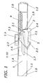
- Figure 1 shows the mechanism in elevation when the drawer is closed and likewise shows a cross-section of the small plate joined to the drawer secured by the latch.
- Figure 2 shows the same elevation with the spring extended after having opened the drawer.
- Figure 3 is an elevation and plan view of the latch.
- the present invention relates to a mechanism for securing the closure of drawers.
- Figure 1 represents an elevation of an embodiment of the mechanism.
- This mechanism is formed by a chassis (1) that consists mainly of a small plate and projections that cover the sides, closing the guide assembly of the drawer that is not shown for access to the interior of the mechanism.
- the means of fastening the chassis (1) to the drawer guide are three, an upper one (1.3) that houses a hooked projection of the drawer guide and two lateral ones (1.1, 1.2) with side projections at the ends that are lodged in slots also present in the drawer guide, one (1.1) of them being configured in a flexible small plate to allow clip-fitting.
- a projection (1.6) that allows the fastening of an end of a spring (4) that works in tension.
- This spring (4) is lodged in a semi-cylindrical recess (1.5) that covers a great part of the length of the chassis (1) to allow its extension.
- the other end of the spring (4) is secured to a projection (2.3) of the latch (2) that is shown in form of an opposing hook.
- this projection (2.3) has, to prevent the spring (4) from escaping, a small projection (2.3.2) facing another (2.3.1) both of smaller width.
- This latch has a pivot (2.1) that is lodged in a slot (1.7) that serves as guide and that allows a longitudinal displacement parallel to the displacement of the drawer.
- the pull of the spring (4) produces a turning couple that is impeded by the support of an upper projection (2.2) on the upper wall (1.10) during the full travel except when the spring (4) is completely extended, since it is opposite a hole (1.4) in which it is lodged, restraining the pull of the spring (4) and impeding thereby that the latch (2) retracts.
- the latch (2) presents on the underside a horizontal surface (2.5) parallel to the small plate (3) joined to the drawer and on both sides of said surface (2.5) opposing projections (2.3) and (2.4) that allow the double action of the latch (2).
- the latch (2) is flanked by two flat surfaces that guide it, one that of the chassis (1) and the other that of the drawer guide upon which it abuts by means of a thickening (2.6) that occupies great part of its area.
- the travel of the latch (2) is likewise limited by a lower projection (1.8) present on the chassis (1).
- the other lower projection (2.4) remains standing out waiting for the drawer to be closed and the small plate (3) to come up against it so that it releases the upper projection (2.2) and the lower projection (2.3) abutting in turn that had been retracted.
- the spring (4) will restore the drawer to its complete closure, the latch being on this side limited in its displacement by a support (1.9) prolongation of the side face toward the interior.
Landscapes
- Engineering & Computer Science (AREA)
- Mechanical Engineering (AREA)
- Drawers Of Furniture (AREA)
- Portable Nailing Machines And Staplers (AREA)
Applications Claiming Priority (2)
| Application Number | Priority Date | Filing Date | Title |
|---|---|---|---|
| ES200100932U ES1048667Y (es) | 2001-04-11 | 2001-04-11 | Mecanismo de seguridad para cierre de cajones |
| ES200100932U | 2001-04-11 |
Publications (2)
| Publication Number | Publication Date |
|---|---|
| EP1249191A2 true EP1249191A2 (de) | 2002-10-16 |
| EP1249191A3 EP1249191A3 (de) | 2004-01-02 |
Family
ID=8497505
Family Applications (1)
| Application Number | Title | Priority Date | Filing Date |
|---|---|---|---|
| EP02380071A Withdrawn EP1249191A3 (de) | 2001-04-11 | 2002-04-01 | Schliesseinrichtung für selbstschliessende Schubladen |
Country Status (2)
| Country | Link |
|---|---|
| EP (1) | EP1249191A3 (de) |
| ES (1) | ES1048667Y (de) |
Cited By (3)
| Publication number | Priority date | Publication date | Assignee | Title |
|---|---|---|---|---|
| EP1491676A2 (de) | 2003-06-28 | 2004-12-29 | LG Electronics Inc. | Gestell für Haushaltsgerät |
| WO2006058351A1 (de) * | 2004-12-03 | 2006-06-08 | Julius Blum Gmbh | Antriebsvorrichtung für ein bewegbar gelagertes möbelteil |
| US20180209659A1 (en) * | 2017-01-26 | 2018-07-26 | Samsung Electronics Co., Ltd | Cooking apparatus |
Citations (1)
| Publication number | Priority date | Publication date | Assignee | Title |
|---|---|---|---|---|
| ES2139476A1 (es) | 1995-02-02 | 2000-02-01 | Ind Ragi S A | Mecanismo de seguridad para cierre de cajones. |
Family Cites Families (3)
| Publication number | Priority date | Publication date | Assignee | Title |
|---|---|---|---|---|
| AT400219B (de) * | 1991-12-24 | 1995-11-27 | Blum Gmbh Julius | Schliessvorrichtung für schubladen |
| AT407602B (de) * | 1994-08-31 | 2001-05-25 | Alfit Ag | Einzugsvorrichtung für schubladen |
| DE9420920U1 (de) * | 1994-12-30 | 1995-02-09 | Klaus Brummernhenrich Kunststoffverarbeitung, Werkzeugbau, Spritzgießerei, 32108 Bad Salzuflen | Schubkasten-Einziehbeschlag |
-
2001
- 2001-04-11 ES ES200100932U patent/ES1048667Y/es not_active Expired - Fee Related
-
2002
- 2002-04-01 EP EP02380071A patent/EP1249191A3/de not_active Withdrawn
Patent Citations (1)
| Publication number | Priority date | Publication date | Assignee | Title |
|---|---|---|---|---|
| ES2139476A1 (es) | 1995-02-02 | 2000-02-01 | Ind Ragi S A | Mecanismo de seguridad para cierre de cajones. |
Cited By (7)
| Publication number | Priority date | Publication date | Assignee | Title |
|---|---|---|---|---|
| EP1491676A2 (de) | 2003-06-28 | 2004-12-29 | LG Electronics Inc. | Gestell für Haushaltsgerät |
| WO2006058351A1 (de) * | 2004-12-03 | 2006-06-08 | Julius Blum Gmbh | Antriebsvorrichtung für ein bewegbar gelagertes möbelteil |
| JP2008521517A (ja) * | 2004-12-03 | 2008-06-26 | ジュリウス ブルム ゲゼルシャフト エム.ビー.エイチ. | 変位可能なように取り付けた家具部品用の駆動器具 |
| US7748799B2 (en) | 2004-12-03 | 2010-07-06 | Julius Blum Gmbh | Drive device for a movably mounted furniture part |
| CN101068487B (zh) * | 2004-12-03 | 2011-04-13 | 尤利乌斯·布卢姆有限公司 | 用于可移动地安置的抽屉的拉出导向装置 |
| US20180209659A1 (en) * | 2017-01-26 | 2018-07-26 | Samsung Electronics Co., Ltd | Cooking apparatus |
| US10746411B2 (en) * | 2017-01-26 | 2020-08-18 | Samsung Electronics Co., Ltd. | Cooking apparatus |
Also Published As
| Publication number | Publication date |
|---|---|
| ES1048667U (es) | 2001-09-01 |
| EP1249191A3 (de) | 2004-01-02 |
| ES1048667Y (es) | 2002-02-01 |
Similar Documents
| Publication | Publication Date | Title |
|---|---|---|
| US5302016A (en) | Automatic pull-in mechanism for drawer guides | |
| KR101223810B1 (ko) | 드로어 활주부를 위한 자동 폐쇄 기구 | |
| US6666306B2 (en) | Damping device for movable furniture parts | |
| CN100413434C (zh) | 用于抽屉的牵引装置 | |
| ES2248188T3 (es) | Dispositivo de desaceleracion de cierre para porciones deslizantes de piezas de muebles. | |
| US9648952B2 (en) | Pressure release slide latch mechanism | |
| US10512328B2 (en) | Retraction device and pull-out guide | |
| KR101143569B1 (ko) | 닫힘조절장치 | |
| KR20000057405A (ko) | 간단하게 작동하는 롤러 커버 | |
| KR100573084B1 (ko) | 슬라이드용 자동폐쇄장치 | |
| JPH0432971Y2 (de) | ||
| TW201225883A (en) | Automatic retraction apparatus for a movable furniture part | |
| EP1249191A2 (de) | Schliesseinrichtung für selbstschliessende Schubladen | |
| US20130287324A1 (en) | Pressure Release Slide Latch Mechanism | |
| KR100537017B1 (ko) | 자동폐쇄장치가 부착된 슬라이드 | |
| JP4847209B2 (ja) | 開き戸の緩衝装置 | |
| CN207270140U (zh) | 一种扣接式自锁滑轨 | |
| CN107198375A (zh) | 缩回装置及拉出导引装置 | |
| ES2868194T3 (es) | Sistema de láminas y mueble de caja | |
| KR20100071366A (ko) | 슬라이딩 도어 시스템 | |
| KR101763393B1 (ko) | 슬라이딩 도어 정위치장치 | |
| JPH1029783A (ja) | エレベーターの敷居装置 | |
| JPH1029784A (ja) | エレベーターの敷居装置 | |
| KR200483169Y1 (ko) | 축사용 도어 잠금장치 | |
| JP2010070990A (ja) | ロック機構付き支柱固定具 |
Legal Events
| Date | Code | Title | Description |
|---|---|---|---|
| PUAI | Public reference made under article 153(3) epc to a published international application that has entered the european phase |
Free format text: ORIGINAL CODE: 0009012 |
|
| AK | Designated contracting states |
Kind code of ref document: A2 Designated state(s): AT BE CH CY DE DK ES FI FR GB GR IE IT LI LU MC NL PT SE TR |
|
| AX | Request for extension of the european patent |
Free format text: AL;LT;LV;MK;RO;SI |
|
| PUAL | Search report despatched |
Free format text: ORIGINAL CODE: 0009013 |
|
| AK | Designated contracting states |
Kind code of ref document: A3 Designated state(s): AT BE CH CY DE DK ES FI FR GB GR IE IT LI LU MC NL PT SE TR |
|
| AX | Request for extension of the european patent |
Extension state: AL LT LV MK RO SI |
|
| STAA | Information on the status of an ep patent application or granted ep patent |
Free format text: STATUS: THE APPLICATION HAS BEEN WITHDRAWN |
|
| 18W | Application withdrawn |
Effective date: 20040212 |