EP1249201B1 - Reinigungsgerät mit Wasserkreislauf - Google Patents
Reinigungsgerät mit Wasserkreislauf Download PDFInfo
- Publication number
- EP1249201B1 EP1249201B1 EP02000432A EP02000432A EP1249201B1 EP 1249201 B1 EP1249201 B1 EP 1249201B1 EP 02000432 A EP02000432 A EP 02000432A EP 02000432 A EP02000432 A EP 02000432A EP 1249201 B1 EP1249201 B1 EP 1249201B1
- Authority
- EP
- European Patent Office
- Prior art keywords
- cleaner
- cleaning water
- suction
- filter
- impeller
- Prior art date
- Legal status (The legal status is an assumption and is not a legal conclusion. Google has not performed a legal analysis and makes no representation as to the accuracy of the status listed.)
- Expired - Lifetime
Links
- XLYOFNOQVPJJNP-UHFFFAOYSA-N water Substances O XLYOFNOQVPJJNP-UHFFFAOYSA-N 0.000 title claims description 135
- 238000004140 cleaning Methods 0.000 claims description 148
- 239000000463 material Substances 0.000 claims description 55
- 239000000428 dust Substances 0.000 claims description 26
- 238000002347 injection Methods 0.000 claims description 23
- 239000007924 injection Substances 0.000 claims description 23
- 239000012530 fluid Substances 0.000 claims description 13
- 239000002245 particle Substances 0.000 claims description 8
- 238000007599 discharging Methods 0.000 claims description 4
- 238000001914 filtration Methods 0.000 claims description 4
- 238000007789 sealing Methods 0.000 claims description 3
- 230000008878 coupling Effects 0.000 description 7
- 238000010168 coupling process Methods 0.000 description 7
- 238000005859 coupling reaction Methods 0.000 description 7
- 239000000356 contaminant Substances 0.000 description 4
- 239000000203 mixture Substances 0.000 description 4
- 238000000034 method Methods 0.000 description 3
- 230000004308 accommodation Effects 0.000 description 2
- 238000003780 insertion Methods 0.000 description 2
- 230000037431 insertion Effects 0.000 description 2
- 239000004745 nonwoven fabric Substances 0.000 description 2
- 238000005086 pumping Methods 0.000 description 2
- 229920000742 Cotton Polymers 0.000 description 1
- 230000009471 action Effects 0.000 description 1
- 230000008901 benefit Effects 0.000 description 1
- 238000011109 contamination Methods 0.000 description 1
- 230000001419 dependent effect Effects 0.000 description 1
- 239000003599 detergent Substances 0.000 description 1
- 230000000694 effects Effects 0.000 description 1
- 239000004744 fabric Substances 0.000 description 1
- 230000005484 gravity Effects 0.000 description 1
- 230000008569 process Effects 0.000 description 1
- 230000003134 recirculating effect Effects 0.000 description 1
- 238000007670 refining Methods 0.000 description 1
- 229920003002 synthetic resin Polymers 0.000 description 1
- 239000000057 synthetic resin Substances 0.000 description 1
Images



Classifications
-
- A—HUMAN NECESSITIES
- A47—FURNITURE; DOMESTIC ARTICLES OR APPLIANCES; COFFEE MILLS; SPICE MILLS; SUCTION CLEANERS IN GENERAL
- A47L—DOMESTIC WASHING OR CLEANING; SUCTION CLEANERS IN GENERAL
- A47L5/00—Structural features of suction cleaners
- A47L5/12—Structural features of suction cleaners with power-driven air-pumps or air-compressors, e.g. driven by motor vehicle engine vacuum
- A47L5/22—Structural features of suction cleaners with power-driven air-pumps or air-compressors, e.g. driven by motor vehicle engine vacuum with rotary fans
-
- A—HUMAN NECESSITIES
- A47—FURNITURE; DOMESTIC ARTICLES OR APPLIANCES; COFFEE MILLS; SPICE MILLS; SUCTION CLEANERS IN GENERAL
- A47L—DOMESTIC WASHING OR CLEANING; SUCTION CLEANERS IN GENERAL
- A47L11/00—Machines for cleaning floors, carpets, furniture, walls, or wall coverings
- A47L11/34—Machines for treating carpets in position by liquid, foam, or vapour, e.g. by steam
-
- A—HUMAN NECESSITIES
- A47—FURNITURE; DOMESTIC ARTICLES OR APPLIANCES; COFFEE MILLS; SPICE MILLS; SUCTION CLEANERS IN GENERAL
- A47L—DOMESTIC WASHING OR CLEANING; SUCTION CLEANERS IN GENERAL
- A47L11/00—Machines for cleaning floors, carpets, furniture, walls, or wall coverings
- A47L11/40—Parts or details of machines not provided for in groups A47L11/02 - A47L11/38, or not restricted to one of these groups, e.g. handles, arrangements of switches, skirts, buffers, levers
- A47L11/4036—Parts or details of the surface treating tools
- A47L11/4044—Vacuuming or pick-up tools; Squeegees
-
- A—HUMAN NECESSITIES
- A47—FURNITURE; DOMESTIC ARTICLES OR APPLIANCES; COFFEE MILLS; SPICE MILLS; SUCTION CLEANERS IN GENERAL
- A47L—DOMESTIC WASHING OR CLEANING; SUCTION CLEANERS IN GENERAL
- A47L11/00—Machines for cleaning floors, carpets, furniture, walls, or wall coverings
- A47L11/40—Parts or details of machines not provided for in groups A47L11/02 - A47L11/38, or not restricted to one of these groups, e.g. handles, arrangements of switches, skirts, buffers, levers
- A47L11/408—Means for supplying cleaning or surface treating agents
- A47L11/4088—Supply pumps; Spraying devices; Supply conduits
-
- A—HUMAN NECESSITIES
- A47—FURNITURE; DOMESTIC ARTICLES OR APPLIANCES; COFFEE MILLS; SPICE MILLS; SUCTION CLEANERS IN GENERAL
- A47L—DOMESTIC WASHING OR CLEANING; SUCTION CLEANERS IN GENERAL
- A47L7/00—Suction cleaners adapted for additional purposes; Tables with suction openings for cleaning purposes; Containers for cleaning articles by suction; Suction cleaners adapted to cleaning of brushes; Suction cleaners adapted to taking-up liquids
- A47L7/0004—Suction cleaners adapted to take up liquids, e.g. wet or dry vacuum cleaners
- A47L7/0009—Suction cleaners adapted to take up liquids, e.g. wet or dry vacuum cleaners with means mounted on the nozzle; nozzles specially adapted for the recovery of liquid
-
- A—HUMAN NECESSITIES
- A47—FURNITURE; DOMESTIC ARTICLES OR APPLIANCES; COFFEE MILLS; SPICE MILLS; SUCTION CLEANERS IN GENERAL
- A47L—DOMESTIC WASHING OR CLEANING; SUCTION CLEANERS IN GENERAL
- A47L7/00—Suction cleaners adapted for additional purposes; Tables with suction openings for cleaning purposes; Containers for cleaning articles by suction; Suction cleaners adapted to cleaning of brushes; Suction cleaners adapted to taking-up liquids
- A47L7/0004—Suction cleaners adapted to take up liquids, e.g. wet or dry vacuum cleaners
- A47L7/0042—Gaskets; Sealing means
-
- A—HUMAN NECESSITIES
- A47—FURNITURE; DOMESTIC ARTICLES OR APPLIANCES; COFFEE MILLS; SPICE MILLS; SUCTION CLEANERS IN GENERAL
- A47L—DOMESTIC WASHING OR CLEANING; SUCTION CLEANERS IN GENERAL
- A47L9/00—Details or accessories of suction cleaners, e.g. mechanical means for controlling the suction or for effecting pulsating action; Storing devices specially adapted to suction cleaners or parts thereof; Carrying-vehicles specially adapted for suction cleaners
- A47L9/10—Filters; Dust separators; Dust removal; Automatic exchange of filters
- A47L9/16—Arrangement or disposition of cyclones or other devices with centrifugal action
- A47L9/1608—Cyclonic chamber constructions
-
- A—HUMAN NECESSITIES
- A47—FURNITURE; DOMESTIC ARTICLES OR APPLIANCES; COFFEE MILLS; SPICE MILLS; SUCTION CLEANERS IN GENERAL
- A47L—DOMESTIC WASHING OR CLEANING; SUCTION CLEANERS IN GENERAL
- A47L9/00—Details or accessories of suction cleaners, e.g. mechanical means for controlling the suction or for effecting pulsating action; Storing devices specially adapted to suction cleaners or parts thereof; Carrying-vehicles specially adapted for suction cleaners
- A47L9/10—Filters; Dust separators; Dust removal; Automatic exchange of filters
- A47L9/16—Arrangement or disposition of cyclones or other devices with centrifugal action
- A47L9/165—Construction of inlets
-
- A—HUMAN NECESSITIES
- A47—FURNITURE; DOMESTIC ARTICLES OR APPLIANCES; COFFEE MILLS; SPICE MILLS; SUCTION CLEANERS IN GENERAL
- A47L—DOMESTIC WASHING OR CLEANING; SUCTION CLEANERS IN GENERAL
- A47L9/00—Details or accessories of suction cleaners, e.g. mechanical means for controlling the suction or for effecting pulsating action; Storing devices specially adapted to suction cleaners or parts thereof; Carrying-vehicles specially adapted for suction cleaners
- A47L9/10—Filters; Dust separators; Dust removal; Automatic exchange of filters
- A47L9/16—Arrangement or disposition of cyclones or other devices with centrifugal action
- A47L9/1658—Construction of outlets
- A47L9/1666—Construction of outlets with filtering means
Definitions
- the present invention relates to a vacuum cleaner and particularly, to a water circulation cleaner capable of removing contaminants on a cleaning object by enabling water cleaning.
- a vacuum cleaner is a cleaning instrument for sucking and removing foreign materials existing on cleaning objects by a suction force generated of a fan motor assembly installed in a main body.
- vacuum cleaners are composed so that it can suck and remove foreign materials by a suction force, it can remove foreign materials such as dusts and the like existing on the surface or in the vicinity of the cleaning object but it is difficult to remove foreign materials on the cleaning object or contaminants or spots on the cleaning object.
- cleaners having a brush or duster or wet duster in a suction head of a cleaner are developed to remove foreign materials which are attached to the cleaning object and not easily separated or spots formed on the cleaning object.
- the vacuum cleaners having a brush or duster is limited in completely separating foreign materials abutting the brush or duster on the cleaning object and accordingly cleaning efficiency is insufficient.
- the above vacuum cleaner also has the disadvantage that its use is inconvenient since the duster must be often shaken and replaced.
- a water circulation cleaner having the features of the preamble of claim 1 is known ( US-A-5,432,975 ), which, however, requires two pumping means, one for creating the vacuum necessary for the sucking action and one for developing high pressure in order to expel clean water from the injection nozzle.
- the object of the present invention is to solve the above problems of conventional art cleaners and to provide an improved water circulation cleaner capable to easily remove foreign materials such as spots and the like as well as dusts existing on a cleaning object by sucking foreign materials from the cleaning object after ejecting cleaning water onto the cleaning object using only one pumping means.
- Such water circulation cleaner offers the advantage that it needs only one pump for creating the necessary vacuum for sucking dirt water from the surface to be cleaned and for ejecting the recycled clean water onto the same surface.
- a water circulation cleaner including a main case, a suction head combined to the lower side of the main case, having a suction port to suck foreign materials and fluid existing on a cleaning object surface, an impeller assembly installed at one side of the main case, for generating suction force, a filter means positioned in the suction passage between the suction head and the impeller assembly, for separating foreign materials contained in suction fluid, a cleaning water tank connected to the discharging port of the impeller assembly in the main case, for storing cleaning water inside and an ejection nozzle positioned in the suction head, for ejecting the cleaning water supplied from the cleaning water tank to the cleaning object surface.
- Rollers are installed at the front and rear sides of the lower surface of the suction head to ease moving of the cleaner.
- the suction can have on the lower surface either a brush member or a duster member to remove foreign materials being abutted to the cleaning object.
- the brush member and the duster member are composed to remove foreign materials from the cleaning object.
- the suction head can have a blade for preventing outflow of the cleaning water ejected from the injection nozzle in the outer area of the suction port.
- the blade can have a trapezoid structure that it is connected to the lower surface of the suction head.
- the suction head having on the lower surface either a brush member or duster member to remove foreign materials being abutted to the cleaning object has a suction port at the upper and rear side of the portion where the brush member and the duster are installed.
- the injection nozzle is positioned between the suction port positioned at the front and the brush member or the duster member.
- the blade can have an elliptic structure that is connected to the lower surface of the suction head.
- the suction port has an oval shape in the internal area of the blade and at least one of the brush member or the duster member is installed at the inner side area of the suction port.
- the pluralities of injection nozzles are formed between the suction port and the brush member or the duster member.
- the blade has a blade end abutted to the bottom surface formed sloped inward where the suction port is positioned.
- the suction pipe forming a suction passage between the suction head and the filter means is provided and includes a non-return valve for preventing a backward flow so that the cleaning water does not move backwardly.
- the suction pipe can have an expansion pipe expanded in the direction of the radius in the middle of itself.
- the filter means is preferrably combined with the impeller assembly outside the main case.
- the filter means can be of hydro-cyclone dust collection structure according to the other embodiment of the present invention.
- the filter means can have a dust collection case having a radius narrowed along from the upper area to the lower area to form a cyclone dust collection structure by gyration movement of fluid.
- the dust collection case can have a protrusion port for sucking the cleaning water containing foreign materials on the upper side surface and an impeller suction tube vertically extending from the impeller assembly at the upper central portion
- the protrusion port protrudes in the direction of tangent line of the dust collection case from a flat surface and the protrusion port is formed sloped downward in the direction to the inner side of the dust collecting case.
- the filter means can have a filter member in a filter case and accordingly when cleaning water sucked to the filter case passes the filter member, foreign material is filtered.
- the filter means can include a filter case having a protrusion port on the side surface to suck cleaning water, a cap where an impeller suction pipe of the impeller assembly passes being combined at the upper portion of the filter case separably and a filter member for filtering foreign materials.
- the filter member can include a first filter member positioned at the inner lower portion of the filter case, having a relatively small number of meshes to filter foreign materials with large particles and a second filter member positioned at the side of the impeller suction pipe having a relatively large number of meshes than the first filtering member to filter foreign materials with small particles.
- the impeller assembly includes an impeller housing fixed to the main case, an impeller for generating a force for flowing cleaning water containing foreign materials which passed through the filter means at the lower inner portion of the impeller housing and a driving motor installed at the upper inner portion of the impeller housing, for rotary operating the impeller.
- the impeller assembly can further include a sealing means positioned between the impeller and the driving motor, for preventing inflow of the cleaning water to the driving motor.
- the cleaning water tank can be formed in a cylindrical shape extending in the vertical direction, being connected with an inflow tube connected to the impeller assembly and an outflow tube connected to the injection nozzle.
- the inflow tube can have a pressure drawing means for lowering pressure by being opened when pressure between the exhaust side area of the impeller assembly and the cleaning water tank reaches a certain level.
- the pressure drawing means can include a pressure drawing tube diverged from the inflow tube and connected to the outside of the main case and a pressure valve installed in the pressure drawing tube, being opened when the pressure reaches a certain level.
- An open/close valve for opening and closing the tank can be installed in the outflow tube to prevent outflow of the cleaning water stored in the cleaning water tank.
- a supply tube communicating with the outside of the main case can be connected to the cleaning water tank to fill the tank with cleaning water and a cap is installed at the inlet portion of the supply tube to close the closing water tank.
- the water circulation cleaner in accordance with the present invention can clean indoor areas as well as concrete floor such as bathroom and the like more cleanly by enabling water cleaning injecting cleaning water in the cleaning object area.
- Figures 1 to 7 show a water circulation cleaner according to an embodiment of the present invention.
- the water circulation cleaner includes a main case 11 where an accommodation space is formed, a suction head 21 positioned at the lower side of the main case 11 as a single body movably, an impeller assembly 30 installed in the main case 11, for generating suction force, a filter unit 51 positioned in the suction passage between the suction head 21 and the impeller assembly 30, for separating foreign materials contained in suction fluid, a cleaning water tank 41 connected to the discharging port 31A of the impeller assembly 30 in the main case for storing cleaning water inside, and an injection nozzle 61 positioned in the suction head 21, for injecting the cleaning water supplied from the cleaning water tank 41 to the cleaning object surface.
- an accommodation space is formed lengthened in the vertical direction and a handle 12 is installed at the upper end portion so that the user can use the cleaner.
- rollers 15 are installed at the front and rear sides of the bottom surface of the suction head to ease moving of the cleaner and coupling portions 27 and 28 formed as a groove shape, for installing a brush member 65 for removing foreign materials being abutted to a cleaning object and a duster member 71 detachably are formed at the center portion of the bottom.
- the brush member 65 includes a plurality of brushes 67 installed on the lower surface of a brush case 66 and an insertion portion 68 combined to the suction head 21 being protruded on the upper surface of the brush case 66 and inserted in the coupling portion 27.
- the duster member 71 includes a duster case 72 composed of synthetic resin member, a duster 74 composed of nonwoven fabric, cotton fabrics, sponge and the like to wipe foreign materials being abutted on the cleaning object and fixed on the bottom surface of the duster case 72 and an insertion portion 75 protruded on the upper surface of the duster case 72 and inserted in and combined to the coupling portion 28 of the suction head 21.
- the brush member 65 is installed at the front and the duster member 71 is installed at the rear. Accordingly, the foreign materials separated from the cleaning object by the brush member 65 are wiped by the duster member 71 and completely removed.
- a blade 63 is installed to form a square edge shape on the external area of the coupling portions 27 and 28 where the brush member 65 and the duster member 71 are installed.
- the blade 63 is composed of rubber member and the like being abutted to the bottom surface elastically so that the cleaning water can be easily sucked under the condition that the cleaning water is positioned at the inner side of the blade square area and the cleaning water injected from the injection nozzle 61 is not flown to the outside of the area at the same time.
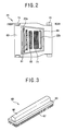
- the blade 63 has an trapezoid shape as shown in Figure 2 , that is, the front portion of the suction head 21 is longer than the rear portion and the side portions are formed sloped to the moving direction of the cleaner.
- the blade 63 has an end blade 63 formed sloped inwardly and it is to flow foreign material to the internal area of the blade easily and prevent outflow of the foreign material or cleaning water in the internal area of the blade to the external area of the blade.
- a pair of suction ports 22A and 22B are formed at the front and rear sides centering around the coupling portions 27 and 28 where the brush member 65 and the duster member 71 are formed so that the cleaning water and foreign material are sucked to the internal area of the blade.
- a plurality of injection nozzles 61 are installed between the suction port 22A positioned at the front side and the coupling portion 27 where the brush member 65 is installed to inject the cleaning water on the bottom surface of the cleaning object.
- a suction pipe 23 vertically connected from the main case 11 is installed between the suction port 22 of the suction head 21 and the filter unit 51.
- the suction pipe 23 is joined by tubes connected to the suction ports 22A and 22B and a second pipe 23B is connected to the filter unit 51.
- An expansion pipe 24 expanded in the radius direction is formed between the first pipe 23A and the second pipe 23B.
- a check valve 25 which is a backward-flow-preventing-valve for preventing backward flow of the sucked cleaning water is installed at the inlet portion of the expansion pipe 24.
- a plurality of stoppers 26 are protruded to restrict upward flow of the check valve 25 when the cleaning water is sucked.
- the filter unit 51 connected between the suction pipe 23 and the impeller assembly 30, for separating foreign material included in the sucked cleaning water is installed at the front side of the main case 11.
- the filter unit 51 is composed of the hydro-cyclone dust collection structure.
- Such filter unit 51 is composed of a dust collection case 52 having a handle 52B and it is installed at the lower side of the impeller assembly 30 separably.
- the dust collection case 52 is formed as a cylindrical structure which is narrowed along from the upper area to the lower area to have a cyclone dust collection structure by gyration movement of fluid
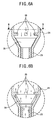
- the dust collection case 52 has an opened upper portion and is combined to the impeller assembly 30. At the center portion of the case, an impeller suction tube 32 expanded vertically from the impeller assembly 30 is positioned. At the upper side surface of the dust collecting case 52, a protrusion port 52A combined with the second pipe 23B of the suction pipe 23 is formed to suck the cleaning water including foreign materials.
- the second pipe 23B of the suction tube 23 and the mutual connection portion of the protrusion port 52A are combined in the direction of the tangent line of the dust collection case 52 as shown in Figure 7 at the view of a flat surface and are formed sloped downwardly in the direction of the inner side of the dust collection case as shown in Figure 1 .
- the impeller assembly 30 is installed at the upper portion of the main case 11 and a part of the impeller assembly 30 is installed exposed to the front side of the main case 11.
- the impeller assembly 30 includes an impeller housing 37 fixed to the main case, an impeller 31 positioned at the lower inner portion of the impeller housing 37, for generating suction force so that the cleaning water including foreign materials is sucked to the suction head 21 and the filter unit 51 and a driving motor 35 installed at the upper inner portion of the impeller housing 37, for rotary operating the impeller 31.
- a sealing portion 36 having a mechanical seal or oil seal is positioned between the impeller 31 and the driving motor 35 to block the inflow of the cleaning water flown to the inner portion of the impeller 31 and transmit the driving force of the driving motor 35.
- the cleaning water tank 41 is installed to supply the cleaning water to the injection nozzle 61 under the condition that the cleaning water is stored.
- the cleaning water tank 41 is formed as a cylindrical shape lengthened in the upper and lower direction and an inflow tube 42 connected with the outlet port 31A of the impeller 31 is combined with the upper side of the tank.
- An outflow tube 44 connected to the injection nozzle 61, for injecting the cleaning water on the bottom surface is combined to the lower side.
- a supply tube 43 communicated from the upper portion of the main case 11 is connected to the cleaning water tank 41 to be filled with the cleaning water and a cap 43A is installed at the inlet portion of the supply tube 43 to close the cleaning water tank 41.
- a pressure drawing tube is connected to the outside of the main case 11 and a pressure valve 34 opened when the pressure is higher than a certain level is installed in the pressure drawing tube 33 so that the pressure between the impeller which is a outlet side area and the cleaning water tank 41 can be drawn when it is higher than a certain level.
- a filter member and the like can be installed at the front and rear sides of the pressure valve 34 to block moisture including the cleaning water and exhaust only air.
- An open/close valve 45 is installed in the outflow tube 44 so that the cleaning water stored in the cleaning water tank does not outflow when the cleaner is not in use. It is desirable that a solenoid valve operated according to signals of a controlling part (not shown) for controlling various operations of the cleaner is applied as the open/close valve 45 and a manual valve which a user can open and close at need can be used.
- the brush member 65 can be used being combined with the duster member 71.
- the cleaning water stored in the cleaning water tank 41 flows along the outflow tube 44 and is injected to the bottom surface through the respective injection nozzles 61 positioned at the lower portion of the suction head 21.
- the blade installed in the suction head 21 prevents the cleaning water injected through the injection nozzle 61 from being leaked to the outside of the suction head 21 and restricts the flow of the cleaning water in the inner side area of the blade 63, thus to suck the cleaning water injected from the injection nozzle 61 through the suction ports 22A and 22B easily.
- the cleaning water sucked through the respective suction ports 22A and 22B flows upward along the suction pipe 23 and then the cleaning water flown the inside of the dust collection case 52 flows downwards gyration along the inside diameter surface of the dust collection case 52.
- the cleaning water exhausted from the impeller 31 is flown to the inside of the cleaning water tank 41 again and flows to the injection nozzle 61 along the outflow tube 44.
- the cleaner can operate water cleaning performance circulating the cleaning water along the above process.
- cleaning can be performed efficiently as described above after inserting and combining only duster member 71 in the coupling portion 28 formed on the lower surface of the suction head 21 and supplying proper amount of cleaning water in the cleaning water tank 41.
- the brush member can be used combined with the duster member 71 as described above.
- the cleaning efficiency can be improved if cleaning is performed again after exchanging the cleaning water inside the cleaning water tank 41 into clean water after performing cleaning circulating the cleaning water and supplying a proper amount of cleansing agent through the supply tube 43.
- the dust collection case 52 is separated from the impeller housing 37 and the suction pipe 23 and the cleaning operation is easily completed by removing the foreign materials in the inside the case.
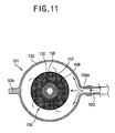
- FIGS 8 to 11 are views showing the water circulation cleaner according to the other embodiment of the present invention.
- the water circulation cleaner includes a main case 111, a suction head 121 combined at the lower side of the main case 111 as a single body, an impeller assembly 130 positioned in the main case 111 for generating a suction force, a filter unit 151 positioned in the suction passage between the suction head 121 and the impeller assembly 130, for separating foreign materials included in the suction fluid, a cleaning water tank 141 installed in the main case 111 and connected to the discharging port of the impeller assembly 130, for storing the cleaning water inside, and injection nozzles 161 positioned on the bottom surface of the suction head 121 for injecting the cleaning water supplied from the cleaning water tank 141 on the bottom surface which is the cleaning object.
- Such water circulation cleaner according to the other embodiment of the present invention basically has the same or similar composition to that of the formerly described embodiment except the composition of the suction head 121 and the filter unit 151. Therefore, the composition will be described centering around the different parts from the above-described embodiment.
- rollers 115 are installed at the front, back, right and left sides of the suction head 121, and a blade 163 for preventing leakage of cleaning water is installed on the lower surface.
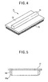
- the blade 163 is installed having an elliptic shape on the bottom surface of the suction head 121.
- a suction port 122 also having an elliptic shape is formed and a duster member 171 having an elliptic shape is combined at the inner side of the suction port 122 separably.
- a brush member can be used being combined instead of the duster member 171.
- a plurality of injection nozzles 161 are installed between the suction port 122 and the duster member 171 to inject the cleaning water supplied from the cleaning water tank 141 to the bottom surface.
- the blade 163, suction port 122, duster member 171 and the like are installed in the suction head 121 according to the other embodiment of the present invention to have an elliptic structure.
- the filter unit 151 of the above described embodiment employs the cyclone dust collection method and on the other hand, a filter member 155 of refining method is used in the other embodiment.
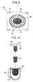
- filter members 155 having a 'U' shape double filter structure are installed inside a filter cap 153 and filter case 152 combined each other.
- a protrusion port 152A connected to a suction pipe 123 is formed at the side surface and an impeller suction pipe 132 composing the suction side of an impeller 131 passes through the center portion of the filter cap 153.
- the filter member 155 includes a first filter member 156 positioned at the inner lower portion of the filter case 152 having a relatively small number of meshes to filter large particles, a second filter member 157 positioned at the side of the impeller suction pipe 132 having a relatively large number of meshes to filter small particles.
- the first filter member 156 having the conventional mesh screen structure separates foreign materials included in the suction fluid and the second filter member 157 is composed of filter materials such as nonwoven fabric and the like covered on the circumference of a supporting screen 158 which is fixed to the filter cap 153.
- the second filter member 157 can be composed using filter materials which are conventionally used as an oil filter of a car.
- the brush member or duster member is disclosed as combined on the lower surface of the suction head separably but the cleaner can wipe out foreign materials by having a duster member of a roller shape rotating the duster member centering on the rotation shaft.
- the brush member as a rotatable roller type electric brush, the foreign materials existing in the cleaning object can be removed rotary operating the brush member.
- the water circulation cleaner in accordance with the present invention is composed capable of removing foreign materials recirculating the cleaning water after injecting the water on the cleaning object surface, the foreign materials such as contaminants and the like on the bottom surface can be efficiently removed and floors of bathrooms or concrete floors can be cleaned easily.
Landscapes
- Engineering & Computer Science (AREA)
- Mechanical Engineering (AREA)
- Nozzles For Electric Vacuum Cleaners (AREA)
- Cleaning In General (AREA)
- Cleaning By Liquid Or Steam (AREA)
Claims (31)
- Reinigungsgerät mit Wasserkreislauf mit:einem Hauptgehäuse (11; 111)einem Saugkopf (21; 121), der mit der unteren Seite des Hauptgehäuses verbunden ist, und der eine Saugöffnung (22a, 22b; 122) aufweist, um Fremdstoffe und Fluid aufzusaugen, die auf der Oberfläche eines Reinigungsobjektes vorhanden sind;einer an einer Seite des Hauptgehäuses (11; 111) installierten Laufradanordnung (30; 130), um Saugkraft zu erzeugen;einer Filtervorrichtung (51; 151) zum Abtrennen von in dem Saugfluid enthaltenen Fremdstoffen;einem Reinigungswasserbehälter (41; 141), der mit der Ablauföffnung (31 a) der Laufradanordnung (30; 130) in dem Hauptgehäuse (11; 111) verbunden ist, um im Inneren Reinigungswasser zu speichern; undeiner Einspritzdüse (61; 161), die in dem Saugkopf (21; 121) positioniert ist, um das Reinigungswasser einzuspritzen, das von dem Reinigungswasserbehälter zur Oberfläche des Reinigungsobjektes transportiert wird,dadurch gekennzeichnet, dass
die Filtervorrichtung (51; 151) zum Abtrennen von in dem Saugfluid enthaltenen Fremdstoffen in dem Saugdurchgang zwischen dem Saugkopf (21; 121) und der Laufradanordnung (30; 130) angeordnet ist, und dass das Laufrad (31; 131) schmutziges Fluid von der Oberfläche des Reinigungsobjektes absaugt und recyceltes Reinigungswasser auf die gleiche Oberfläche mit dem erforderlichen Hochdruck spritzt. - Reinigungsgerät gemäß Anspruch 1, wobei Rollen an der Vorder- und Hinterseite der Unterseite des Saugkopfes (21; 121) angebracht sind, um die Bewegung des Reinigungsgerätes zu erleichtern.
- Reinigungsgerät gemäß Anspruch 1, wobei der Saugkopf (21; 121) entweder ein Bürstenelement (65) oder ein Stäuberelement (71; 171) aufweist, um Fremdstoffe zu entfernen, die an der Unterseite des Reinigungsobjektes fest hängen.
- Reinigungsgerät gemäß Anspruch 3, wobei das Bürstenelement (65) und das Stäuberelement (71; 171) dafür vorgesehen sind, Fremdstoffe von dem Reinigungsobjekt zu entfernen.
- Reinigungsgerät gemäß Anspruch 1, wobei der Saugkopf (21; 121) ein Abschirmblatt (63; 163) aufweist, um das Auslaufen des von der Einspritzdüse (61; 161) eingespritzten Reinigungswassers in den Außenbereich der Saugöffnung (221, 22b; 122) zu verhindern.
- Reinigungsgerät gemäß Anspruch 5, wobei das Abschirmblatt (63; 163) einen trapezförmigen Aufbau aufweist und mit der Unterseite des Saugkopfes (21; 121) verbunden ist.
- Reinigungsgerät gemäß Anspruch 6, wobei der Saugkopf (21; 121) entweder ein Bürstenelement (65) oder ein Stäuberelement (71; 171) aufweist, um Fremdstoffe zu entfernen, die an der Unterseite des Reinigungsobjektes anhaften, und wobei die Saugöffnung (22a, 22b; 122) an der Ober- und Rückseite des Bereiches ausgebildet ist, in dem das Bürstenelement und der Stäuber installiert sind.
- Reinigungsgerät gemäß Anspruch 7, wobei die Einspritzdüse (61; 161) zwischen der an der Vorderseite angeordneten Saugöffnung (22a, 22b; 122) und dem Bürstenelement (65) oder dem Stäuberelement (71; 171) positioniert ist.
- Reinigungsgerät gemäß Anspruch 5, wobei das Abschirmblatt (163) einen ovalen Aufbau aufweist und mit der Unterseite des Saugkopfes (121) verbunden ist.
- Reinigungsgerät gemäß Anspruch 9, wobei die Saugöffnung (122) als ovale Form in dem Innenbereich des Abschirmblattes (163) ausgebildet ist.
- Reinigungsgerät gemäß Anspruch 10, wobei zumindest eines des Bürstenelementes (65) oder des Stäuberelementes (71; 171) an dem Innenseitenbereich der Saugöffnung (22a, 22b; 122) angebracht ist.
- Reinigungsgerät gemäß Anspruch 10, wobei die Vielzahl von Einspritzdüsen (61; 161) zwischen der Saugöffnung (22a, 22b; 122) und dem Bürstenelement (65) oder dem Stäuberelement (71; 171) ausgebildet sind.
- Reinigungsgerät gemäß Anspruch 5, wobei das Abschirmblatt (63) ein Endblatt (63a) aufweist, das an die Unterseite anliegt, welche dort, wo die Saugöffnung (22a, 22b) positioniert ist, nach innen geneigt ausgebildet ist.
- Reinigungsgerät gemäß Anspruch 1, wobei ein Saugrohr (23; 123) zum Ausbilden eines Saugdurchgangs zwischen dem Saugkopf (21; 121) und der Filtervorrichtung (51; 151) und ein Rücklaufschutzventil zum Verhindern eines Rückflusses vorgesehen sind, so dass das Reinigungswasser nicht zurück fließt.
- Reinigungsgerät gemäß Anspruch 14, wobei das Saugrohr (23; 123) ein Aufweitungsrohr aufweist, das sich in seiner Mitte in die Richtung des Radius aufweitet.
- Reinigungsgerät gemäß Anspruch 1, wobei die Filtervorrichtung (51; 151) mit der Laufradanordnung (30; 130) außerhalb des Hauptgehäuses (11; 111) verbunden ist.
- Reinigungsgerät gemäß Anspruch 1, wobei die Filtervorrichtung (51; 151) eine Staubsammelstruktur mit Waschzyklon aufweist.
- Reinigungsgerät gemäß Anspruch 17, wobei die Filtervorrichtung (51; 151) aus einem Staubsammelgehäuse (52; 152) mit einem Radius besteht, der sich von dem oberen Bereich bis zum unteren Bereich hin verengt, um eine Zyklonstaubsammelstruktur unter Kreisdrehungsbewegung des Fluids zu bilden.
- Reinigungsgerät gemäß Anspruch 18, wobei das Staubsammelgehäuse (52; 152) eine vorstehende Öffnung (52a; 152a) aufweist, um das Fremdstoffe enthaltende Reinigungswasser auf der Oberfläche der Oberseite aufzusaugen, und ein Laufradsaugrohr (32; 132), das sich vertikal von der Laufradanordnung (30; 130) an dem oberen Mittelbereich ausdehnt.
- Reinigungsgerät gemäß Anspruch 19, wobei die vorstehende Öffnung (52a; 152a) von einer flachen Fläche in die Richtung der Tangente mit dem Staubsammelgehäuse (52; 152) vorsteht.
- Reinigungsgerät gemäß Anspruch 19, wobei die vorstehende Öffnung (52a; 152a) nach unten in Richtung der Innenseite des Staubsammelgehäuses (52; 152) geneigt ausgebildet ist.
- Reinigungsgerät gemäß Anspruch 1, wobei die Filtervorrichtung (51; 151) ein Filterelement (155) in einem Filtergehäuse (152) aufweist und dementsprechend werden, wenn in das Filtergehäuse gesaugtes Reinigungswasser das Filterelement durchfließt, Fremdstoffe gefiltert.
- Reinigungsgerät gemäß Anspruch 22, wobei die Filtervorrichtung (151) aufweist:ein Filtergehäuse (152) mit einer vorstehenden Öffnung (152a) auf der Seitenfläche zum Ansaugen von Reinigungswasser;eine Abdeckung (153), durch welche ein Laufradsaugrohr (132) der Laufradanordnung (130) läuft, und welche an dem oberen Bereich des Filtergehäuses getrennt befestigt ist; undein Filterelement (155) zum Filtern von Fremdstoffen.
- Reinigungsgerät gemäß Anspruch 22, wobei das Filterelement (155) aufweist:ein erstes Filterelement (156), das in dem unteren Innenbereich des Filtergehäuses (152) angeordnet ist und eine relativ kleine Anzahl von Maschen aufweist, um Fremdstoffe mit großen Partikeln zu filtern; undein zweites Filterelement (157), das an der Seite des Laufradsaugrohrs (132) angeordnet ist und eine verhältnismäßig größere Anzahl von Maschen aufweist als das erste Filterelement, um Fremdstoffe mit kleinen Partikeln zu filtern.
- Reinigungsgerät gemäß Anspruch 1, wobei die Laufradanordnung (30; 130) aufweist:ein Laufradgehäuse (37; 137), das an dem Hauptgehäuse (11; 111) befestigt ist;ein Laufrad (31; 131) zur Erzeugung einer Kraft, um Fremdstoffe enthaltendes Reinigungswasser, das durch die Filtervorrichtung (51; 155) in dem unteren Innenbereich des Laufradgehäuses geflossen ist, fließen zu lassen; undeinen Antriebsmotor (35), der in dem oberen Innenbereich des Laufradgehäuses angebracht ist zur Drehbetätigung des Laufrades.
- Reinigungsgerät gemäß Anspruch 25, wobei die Laufradanordnung (30; 130) ferner aufweist:eine Dichtungsvorrichtung (36), die zwischen dem Laufrad (31; 131) und dem Antriebsmotor (35) angeordnet ist, um das Einfließen von Reinigungswasser in den Antriebsmotor zu verhindern.
- Reinigungsgerät gemäß Anspruch 1, wobei der Reinigungswasserbehälter (41; 141) mit einer zylindrischen Form ausgebildet ist, die sich in vertikaler Richtung verlängert, und er mit einem Einflussrohr (42) in die Laufradanordnung (30; 130) und einem mit der Einspritzdüse (61; 161) verbundenen Ausflussrohr (40) verbunden ist.
- Reinigungsgerät gemäß Anspruch 27, wobei das Einflussrohr (42) eine Druckabzugsvorrichtung (33, 34) aufweist, um durch Öffnung den Druck abzusenken, wenn der Druck zwischen dem Auslassseitenbereich (31 a) der Laufradanordnung (30; 130) und dem Reinigungswasserbehälter (41; 141) eine bestimmte Höhe erreicht.
- Reinigungsgerät gemäß Anspruch 28, wobei die Druckabzugsvorrichtung aufweist:ein Druckabzugsrohr (33), das von dem Einflussrohr (42) abgezweigt und mit der Außenseite des Hauptgehäuses (11; 111) verbunden ist; undein Druckventil (34), das in dem Druckabzugsrohr installiert ist und geöffnet wird, wenn der Druck eine bestimmte Höhe erreicht.
- Reinigungsgerät gemäß einem der Ansprüche 27 bis 29, wobei ein Öffnungs/Schließventil (45) zum Öffnen und Schließen des Behälters (41; 141) in dem Ausflussrohr (44) installiert ist, um den Ausfluss des in dem Reinigungswasserbehälter gespeicherten Reinigungswassers zu verhindern.
- Reinigungsgerät gemäß einem der Ansprüche 27 bis 30, wobei ein Versorgungsrohr (43), das mit der Außenseite des Hauptgehäuses (11; 111) in Verbindung steht, mit dem Reinigungswasserbehälter (41; 141) verbunden ist, um den Behälter mit Reinigungswasser zu füllen, und wobei eine Abdeckung (43a) in dem Einlassbereich des Versorgungsrohres (43) angebracht ist, um den Reinigungswasserbehälter zu schließen.
Applications Claiming Priority (2)
| Application Number | Priority Date | Filing Date | Title |
|---|---|---|---|
| KR10-2001-0019884A KR100404113B1 (ko) | 2001-04-13 | 2001-04-13 | 세척수 순환식 진공청소기 |
| KR2001019884 | 2001-04-13 |
Publications (3)
| Publication Number | Publication Date |
|---|---|
| EP1249201A2 EP1249201A2 (de) | 2002-10-16 |
| EP1249201A3 EP1249201A3 (de) | 2004-12-29 |
| EP1249201B1 true EP1249201B1 (de) | 2008-03-26 |
Family
ID=19708221
Family Applications (1)
| Application Number | Title | Priority Date | Filing Date |
|---|---|---|---|
| EP02000432A Expired - Lifetime EP1249201B1 (de) | 2001-04-13 | 2002-01-08 | Reinigungsgerät mit Wasserkreislauf |
Country Status (6)
| Country | Link |
|---|---|
| US (1) | US6748622B2 (de) |
| EP (1) | EP1249201B1 (de) |
| KR (1) | KR100404113B1 (de) |
| CN (1) | CN1270663C (de) |
| DE (1) | DE60225748T2 (de) |
| RU (1) | RU2223025C2 (de) |
Families Citing this family (33)
| Publication number | Priority date | Publication date | Assignee | Title |
|---|---|---|---|---|
| KR100417428B1 (ko) * | 2001-09-25 | 2004-02-05 | 엘지전자 주식회사 | 물청소 가능한 중앙집진식 진공청소기 |
| PL1653838T3 (pl) * | 2003-08-04 | 2012-12-31 | Koninl Philips Electronics Nv | Odpylacz cyklonowy do oddzielania cząsteczek od strumienia powietrza oraz odkurzacz zawierający taki odpylacz |
| EP1658003B1 (de) * | 2003-08-22 | 2011-07-13 | Bissell Homecare, Inc. | Reinigungsvorrichtung zur nass-/trockenreinigung von freiliegenden fussböden |
| CA2510660A1 (en) * | 2004-06-25 | 2005-12-25 | The Hoover Company | Handle assembly for a cleaning apparatus |
| KR100619755B1 (ko) * | 2004-11-03 | 2006-09-06 | 엘지전자 주식회사 | 습식 업라이트 청소기의 집수통 |
| KR100619754B1 (ko) * | 2004-11-03 | 2006-09-06 | 엘지전자 주식회사 | 건습식 복합형 업라이트 청소기 |
| WO2006091509A2 (en) * | 2005-02-22 | 2006-08-31 | Royal Appliance Mfg. Co. | High pressure extractor |
| KR100662642B1 (ko) * | 2005-06-22 | 2007-01-02 | 삼성광주전자 주식회사 | 물청소 기능을 갖는 진공청소기 |
| US20070163075A1 (en) * | 2006-01-17 | 2007-07-19 | Butler Dennis C | Stair cleaning vacuum cleaner |
| KR100841444B1 (ko) * | 2007-01-24 | 2008-06-25 | 삼성광주전자 주식회사 | 진공청소기의 브러시 및 걸레 겸용 흡입노즐 |
| CN101467856B (zh) * | 2007-12-28 | 2011-02-09 | 朱晓义 | 一种清洁机 |
| JP5209374B2 (ja) | 2008-05-29 | 2013-06-12 | 株式会社マキタ | ダストボックス及び電動工具 |
| CN102244434B (zh) * | 2010-05-11 | 2016-04-06 | 德昌电机(深圳)有限公司 | 电机组件 |
| GB2489408B (en) * | 2011-03-23 | 2015-08-05 | Techtronic Floor Care Tech Ltd | Suction cleaner |
| DE102011121196B4 (de) | 2011-12-16 | 2023-10-05 | Krahnen Gmbh | Nass-Trocken-Kombinationsreinigungsvorrichtung |
| AU2014100145A4 (en) | 2013-03-01 | 2014-03-13 | Bissell Inc. | Surface cleaning apparatus |
| RU2640706C2 (ru) | 2013-07-02 | 2018-01-11 | Альфред Кэрхер Гмбх Унд Ко. Кг | Очистительный всасывающий аппарат |
| CN103330535B (zh) * | 2013-07-03 | 2015-12-09 | 江苏大学 | 一种水射流吸尘器 |
| WO2015039706A1 (de) * | 2013-09-23 | 2015-03-26 | Alfred Kärcher Gmbh & Co. Kg | Saugdüsenvorrichtung für ein reinigungsgerät und reinigungsgerät |
| CN103720436B (zh) * | 2014-01-08 | 2017-01-18 | 中山市众智电器有限公司 | 便携式液体抽汲装置 |
| CN104433948B (zh) * | 2014-12-16 | 2017-04-05 | 中山市金舜家庭用品有限公司 | 抽吸清洁器 |
| CN106308683A (zh) * | 2015-06-18 | 2017-01-11 | 宝时得机械(张家港)有限公司 | 便携式抽吸设备及擦窗机 |
| CN105054863A (zh) * | 2015-08-03 | 2015-11-18 | 吴江市元通纺织品有限公司 | 一种纺织用清洁装置 |
| CN110192804A (zh) * | 2018-02-26 | 2019-09-03 | 江苏美的清洁电器股份有限公司 | 立式吸尘器 |
| CN113520219A (zh) * | 2018-02-26 | 2021-10-22 | 江苏美的清洁电器股份有限公司 | 立式吸尘器 |
| CN108378777B (zh) * | 2018-03-07 | 2020-09-29 | 添可电器有限公司 | 回收桶及其吸尘器 |
| CN108284822A (zh) * | 2018-03-23 | 2018-07-17 | 周波 | 一种清洗、风干一体机 |
| CN109528106B (zh) * | 2018-12-19 | 2024-01-30 | 浙江东亿磁业有限公司 | 家用多功能喷抽吸尘吸水机 |
| CN113367607A (zh) * | 2020-03-10 | 2021-09-10 | 苏州宝时得电动工具有限公司 | 吸尘器的吸水组件及吸尘器 |
| CN113384199B (zh) * | 2020-03-13 | 2022-05-31 | 添可智能科技有限公司 | 地刷及清洁设备 |
| CN114224250B (zh) * | 2021-12-29 | 2023-07-14 | 尚科宁家(中国)科技有限公司 | 一种表面清洁装置的清洁方法 |
| CN114890096B (zh) * | 2022-05-25 | 2024-02-02 | 湖北中烟工业有限责任公司 | 一种输送带清洗机 |
| CN121533657A (zh) * | 2023-04-24 | 2026-02-17 | 帝舍智能科技(武汉)有限公司 | 开放式清洗通道及清洁器 |
Family Cites Families (26)
| Publication number | Priority date | Publication date | Assignee | Title |
|---|---|---|---|---|
| US3235090A (en) * | 1961-12-15 | 1966-02-15 | Univ Oklahoma State | Hydroclones |
| US3594849A (en) * | 1967-10-13 | 1971-07-27 | Chester L Coshow | Cleaning apparatus |
| DE1911990C3 (de) * | 1969-03-10 | 1978-12-07 | Horst 4000 Duesseldorf Kauffeldt | Vorrichtung zum Reinigen von großflächigen Textilauflagen, insbesondere Teppichen oder Teppichboden |
| US3699607A (en) * | 1970-07-07 | 1972-10-24 | Town & Country Cleaners Franch | Carpet cleaning apparatus |
| GB1432557A (en) * | 1973-02-20 | 1976-04-22 | Dynaclean Ltd | Apparatus for cleaning a substantially -non-porous- surface such as a floor or wall |
| FR2321259A1 (fr) * | 1975-08-21 | 1977-03-18 | Warwick Pump And Engineering | Machine a laver les sols |
| GB2030040A (en) * | 1978-09-13 | 1980-04-02 | Elan Pressure Clean Ltd | Floor cleaning unit |
| US4348783A (en) * | 1980-11-10 | 1982-09-14 | Tennant Company | Scrubbing machine with selective recycle |
| US4466155A (en) * | 1982-11-22 | 1984-08-21 | Grave Dale L | Recycling cleaning apparatus |
| US4462137A (en) * | 1983-01-03 | 1984-07-31 | Shop-Vac Corporation | Electric vacuum cleaner |
| DE3518545C1 (de) * | 1985-05-23 | 1986-12-18 | Alfred Kärcher GmbH & Co, 7057 Winnenden | Naßreinigungsgerät für Bodenbeläge |
| US4930178A (en) * | 1985-07-17 | 1990-06-05 | Monson Clifford L | Compact self-contained recycling extraction cleaner |
| DE3540783A1 (de) * | 1985-11-16 | 1987-05-21 | Hako Gmbh & Co | Fahrbare nassreinigungsmaschine |
| ATE101792T1 (de) * | 1989-12-01 | 1994-03-15 | William Hendrick Williams | Nass- und trockensauger. |
| US5299608A (en) * | 1992-03-16 | 1994-04-05 | The Hoover Company | Sealed coupling for a fluid container |
| US5331713A (en) * | 1992-07-13 | 1994-07-26 | White Consolidated Industries, Inc. | Floor scrubber with recycled cleaning solution |
| US5354347A (en) * | 1993-03-29 | 1994-10-11 | E. B. S. Equipment Broker Services, Inc. | Vacuum cleaner utilizing water to capture dirt and debris |
| CA2123740C (en) * | 1993-05-19 | 2002-12-17 | Hee-Gwon Chae | Electric vacuum cleaner |
| US5432975A (en) * | 1993-11-04 | 1995-07-18 | Cfr Corporation | Self-contained continuous flow recycling apparatus |
| US5589080A (en) * | 1995-04-04 | 1996-12-31 | Cfr Corporation | Liquid recycling system with moving concentrated counterflow for filter clearance |
| JP3295285B2 (ja) * | 1995-09-29 | 2002-06-24 | アマノ株式会社 | 洗浄水のリサイクル機能を備えた床面洗浄機 |
| US6055699A (en) * | 1996-10-16 | 2000-05-02 | Cfr Corporation | Cleaning tool head with multi-filament seal |
| JP3498826B2 (ja) * | 1997-06-20 | 2004-02-23 | 象印マホービン株式会社 | 吸引掃除機 |
| US5943730A (en) * | 1997-11-24 | 1999-08-31 | Tennant Company | Scrubber vac-fan seal |
| US6195835B1 (en) * | 1998-12-02 | 2001-03-06 | Samsung Kwangju Electronics Co., Ltd. | Vacuum cleaner having a cyclone dust collecting device |
| JP3568837B2 (ja) * | 1999-09-30 | 2004-09-22 | アマノ株式会社 | 床面洗浄清掃機 |
-
2001
- 2001-04-13 KR KR10-2001-0019884A patent/KR100404113B1/ko not_active Expired - Fee Related
-
2002
- 2002-01-04 RU RU2002100705/12A patent/RU2223025C2/ru not_active IP Right Cessation
- 2002-01-08 EP EP02000432A patent/EP1249201B1/de not_active Expired - Lifetime
- 2002-01-08 DE DE60225748T patent/DE60225748T2/de not_active Expired - Lifetime
- 2002-01-11 US US10/042,151 patent/US6748622B2/en not_active Expired - Fee Related
- 2002-01-14 CN CNB021016569A patent/CN1270663C/zh not_active Expired - Fee Related
Also Published As
| Publication number | Publication date |
|---|---|
| US6748622B2 (en) | 2004-06-15 |
| EP1249201A2 (de) | 2002-10-16 |
| KR100404113B1 (ko) | 2003-11-03 |
| RU2223025C2 (ru) | 2004-02-10 |
| CN1270663C (zh) | 2006-08-23 |
| DE60225748D1 (de) | 2008-05-08 |
| DE60225748T2 (de) | 2009-04-09 |
| US20020148071A1 (en) | 2002-10-17 |
| KR20020079164A (ko) | 2002-10-19 |
| EP1249201A3 (de) | 2004-12-29 |
| CN1381218A (zh) | 2002-11-27 |
Similar Documents
| Publication | Publication Date | Title |
|---|---|---|
| US6748622B2 (en) | Water circulation cleaner | |
| KR920004231B1 (ko) | 건식진공청소기를 습식으로 전환하여 사용하기 위한 진공청소기용 부대장치 | |
| CN214073161U (zh) | 多功能服务站、扫地机器人系统 | |
| KR100565262B1 (ko) | 건습식 복합형 업라이트 청소기 | |
| CN109700378B (zh) | 用于真空吸尘器的表面清洁头 | |
| KR100619754B1 (ko) | 건습식 복합형 업라이트 청소기 | |
| CN114424905A (zh) | 多功能服务站、扫地机器人系统及其控制方法 | |
| CN209808210U (zh) | 用于湿式地面清洁设备的地面吸嘴 | |
| KR100608666B1 (ko) | 건/습식 겸용 청소기 | |
| KR20060037185A (ko) | 건습식 복합형 업라이트 청소기 | |
| CN111743454A (zh) | 用于湿式地面清洁设备的地面吸嘴 | |
| EP4289321A1 (de) | Saugdüse für extraktionsreiniger | |
| CN218943225U (zh) | 一种清洗效果好的表面清洁装置 | |
| KR200381912Y1 (ko) | 로봇청소기 | |
| CN115413973A (zh) | 用于表面清洁设备的地刷组件 | |
| KR102368259B1 (ko) | 청소기 헤드 장치 및 이를 포함하는 청소기 | |
| KR100595576B1 (ko) | 습식 업라이트 청소기의 집수통 | |
| CN221153969U (zh) | 一种刷件和应用该刷件的地刷模块及清洁机 | |
| KR100613484B1 (ko) | 물걸레 청소기용 흡입구 헤드 | |
| KR920010681B1 (ko) | 건식청소와 물청소가 가능한 습건식 진공청소기 | |
| KR920010684B1 (ko) | 습건식 진공청소기의 회수세액 제거장치 | |
| CN222549114U (zh) | 吸尘器用手持式湿清洁刷头组件 | |
| KR102145880B1 (ko) | 다목적 청소장치 | |
| CN221383436U (zh) | 一种刷件和应用该刷件的地刷模块及清洁机 | |
| CN221153964U (zh) | 一种刷件和应用该刷件的地刷模块及清洁机 |
Legal Events
| Date | Code | Title | Description |
|---|---|---|---|
| PUAI | Public reference made under article 153(3) epc to a published international application that has entered the european phase |
Free format text: ORIGINAL CODE: 0009012 |
|
| AK | Designated contracting states |
Kind code of ref document: A2 Designated state(s): AT BE CH CY DE DK ES FI FR GB GR IE IT LI LU MC NL PT SE TR |
|
| AX | Request for extension of the european patent |
Free format text: AL;LT;LV;MK;RO;SI |
|
| PUAL | Search report despatched |
Free format text: ORIGINAL CODE: 0009013 |
|
| AK | Designated contracting states |
Kind code of ref document: A3 Designated state(s): AT BE CH CY DE DK ES FI FR GB GR IE IT LI LU MC NL PT SE TR |
|
| AX | Request for extension of the european patent |
Extension state: AL LT LV MK RO SI |
|
| 17P | Request for examination filed |
Effective date: 20050531 |
|
| AKX | Designation fees paid |
Designated state(s): DE FR GB |
|
| GRAP | Despatch of communication of intention to grant a patent |
Free format text: ORIGINAL CODE: EPIDOSNIGR1 |
|
| GRAS | Grant fee paid |
Free format text: ORIGINAL CODE: EPIDOSNIGR3 |
|
| GRAA | (expected) grant |
Free format text: ORIGINAL CODE: 0009210 |
|
| AK | Designated contracting states |
Kind code of ref document: B1 Designated state(s): DE FR GB |
|
| REG | Reference to a national code |
Ref country code: GB Ref legal event code: FG4D |
|
| REF | Corresponds to: |
Ref document number: 60225748 Country of ref document: DE Date of ref document: 20080508 Kind code of ref document: P |
|
| ET | Fr: translation filed | ||
| PLBE | No opposition filed within time limit |
Free format text: ORIGINAL CODE: 0009261 |
|
| STAA | Information on the status of an ep patent application or granted ep patent |
Free format text: STATUS: NO OPPOSITION FILED WITHIN TIME LIMIT |
|
| 26N | No opposition filed |
Effective date: 20081230 |
|
| PGFP | Annual fee paid to national office [announced via postgrant information from national office to epo] |
Ref country code: GB Payment date: 20121128 Year of fee payment: 12 |
|
| PGFP | Annual fee paid to national office [announced via postgrant information from national office to epo] |
Ref country code: FR Payment date: 20130104 Year of fee payment: 12 |
|
| PGFP | Annual fee paid to national office [announced via postgrant information from national office to epo] |
Ref country code: DE Payment date: 20121121 Year of fee payment: 12 |
|
| REG | Reference to a national code |
Ref country code: DE Ref legal event code: R119 Ref document number: 60225748 Country of ref document: DE |
|
| GBPC | Gb: european patent ceased through non-payment of renewal fee |
Effective date: 20140108 |
|
| REG | Reference to a national code |
Ref country code: DE Ref legal event code: R119 Ref document number: 60225748 Country of ref document: DE Effective date: 20140801 |
|
| PG25 | Lapsed in a contracting state [announced via postgrant information from national office to epo] |
Ref country code: DE Free format text: LAPSE BECAUSE OF NON-PAYMENT OF DUE FEES Effective date: 20140801 |
|
| REG | Reference to a national code |
Ref country code: FR Ref legal event code: ST Effective date: 20140930 |
|
| PG25 | Lapsed in a contracting state [announced via postgrant information from national office to epo] |
Ref country code: FR Free format text: LAPSE BECAUSE OF NON-PAYMENT OF DUE FEES Effective date: 20140131 Ref country code: GB Free format text: LAPSE BECAUSE OF NON-PAYMENT OF DUE FEES Effective date: 20140108 |