EP1249276A2 - Katalytisches Element zur Desinfektion von z. B. Kontaktlinsen - Google Patents
Katalytisches Element zur Desinfektion von z. B. Kontaktlinsen Download PDFInfo
- Publication number
- EP1249276A2 EP1249276A2 EP02010368A EP02010368A EP1249276A2 EP 1249276 A2 EP1249276 A2 EP 1249276A2 EP 02010368 A EP02010368 A EP 02010368A EP 02010368 A EP02010368 A EP 02010368A EP 1249276 A2 EP1249276 A2 EP 1249276A2
- Authority
- EP
- European Patent Office
- Prior art keywords
- catalytic element
- catalytic
- container
- cap
- retaining
- Prior art date
- Legal status (The legal status is an assumption and is not a legal conclusion. Google has not performed a legal analysis and makes no representation as to the accuracy of the status listed.)
- Withdrawn
Links
Images


Classifications
-
- A—HUMAN NECESSITIES
- A61—MEDICAL OR VETERINARY SCIENCE; HYGIENE
- A61L—METHODS OR APPARATUS FOR STERILISING MATERIALS OR OBJECTS IN GENERAL; DISINFECTION, STERILISATION OR DEODORISATION OF AIR; CHEMICAL ASPECTS OF BANDAGES, DRESSINGS, ABSORBENT PADS OR SURGICAL ARTICLES; MATERIALS FOR BANDAGES, DRESSINGS, ABSORBENT PADS OR SURGICAL ARTICLES
- A61L2/00—Disinfection or sterilisation of materials or objects, in general; Accessories therefor
- A61L2/16—Disinfection or sterilisation of materials or objects, in general; Accessories therefor using chemical substances
- A61L2/18—Liquid substances
- A61L2/186—Peroxide solutions
-
- A—HUMAN NECESSITIES
- A45—HAND OR TRAVELLING ARTICLES
- A45C—PURSES; LUGGAGE; HAND CARRIED BAGS
- A45C11/00—Receptacles for purposes not provided for in groups A45C1/00-A45C9/00
- A45C11/005—Contact lens cases
-
- A—HUMAN NECESSITIES
- A61—MEDICAL OR VETERINARY SCIENCE; HYGIENE
- A61L—METHODS OR APPARATUS FOR STERILISING MATERIALS OR OBJECTS IN GENERAL; DISINFECTION, STERILISATION OR DEODORISATION OF AIR; CHEMICAL ASPECTS OF BANDAGES, DRESSINGS, ABSORBENT PADS OR SURGICAL ARTICLES; MATERIALS FOR BANDAGES, DRESSINGS, ABSORBENT PADS OR SURGICAL ARTICLES
- A61L12/00—Methods or apparatus for disinfecting or sterilising contact lenses; Accessories therefor
- A61L12/02—Methods or apparatus for disinfecting or sterilising contact lenses; Accessories therefor using physical phenomena, e.g. electricity, ultrasound or ultrafiltration
-
- A—HUMAN NECESSITIES
- A61—MEDICAL OR VETERINARY SCIENCE; HYGIENE
- A61L—METHODS OR APPARATUS FOR STERILISING MATERIALS OR OBJECTS IN GENERAL; DISINFECTION, STERILISATION OR DEODORISATION OF AIR; CHEMICAL ASPECTS OF BANDAGES, DRESSINGS, ABSORBENT PADS OR SURGICAL ARTICLES; MATERIALS FOR BANDAGES, DRESSINGS, ABSORBENT PADS OR SURGICAL ARTICLES
- A61L12/00—Methods or apparatus for disinfecting or sterilising contact lenses; Accessories therefor
- A61L12/08—Methods or apparatus for disinfecting or sterilising contact lenses; Accessories therefor using chemical substances
- A61L12/086—Container, accessories or devices therefor
-
- A—HUMAN NECESSITIES
- A61—MEDICAL OR VETERINARY SCIENCE; HYGIENE
- A61L—METHODS OR APPARATUS FOR STERILISING MATERIALS OR OBJECTS IN GENERAL; DISINFECTION, STERILISATION OR DEODORISATION OF AIR; CHEMICAL ASPECTS OF BANDAGES, DRESSINGS, ABSORBENT PADS OR SURGICAL ARTICLES; MATERIALS FOR BANDAGES, DRESSINGS, ABSORBENT PADS OR SURGICAL ARTICLES
- A61L12/00—Methods or apparatus for disinfecting or sterilising contact lenses; Accessories therefor
- A61L12/08—Methods or apparatus for disinfecting or sterilising contact lenses; Accessories therefor using chemical substances
- A61L12/12—Non-macromolecular oxygen-containing compounds, e.g. hydrogen peroxide or ozone
- A61L12/124—Hydrogen peroxide; Peroxy compounds
- A61L12/128—Hydrogen peroxide; Peroxy compounds neutralised with catalysts
-
- A—HUMAN NECESSITIES
- A61—MEDICAL OR VETERINARY SCIENCE; HYGIENE
- A61L—METHODS OR APPARATUS FOR STERILISING MATERIALS OR OBJECTS IN GENERAL; DISINFECTION, STERILISATION OR DEODORISATION OF AIR; CHEMICAL ASPECTS OF BANDAGES, DRESSINGS, ABSORBENT PADS OR SURGICAL ARTICLES; MATERIALS FOR BANDAGES, DRESSINGS, ABSORBENT PADS OR SURGICAL ARTICLES
- A61L2/00—Disinfection or sterilisation of materials or objects, in general; Accessories therefor
- A61L2/26—Accessories
-
- B—PERFORMING OPERATIONS; TRANSPORTING
- B01—PHYSICAL OR CHEMICAL PROCESSES OR APPARATUS IN GENERAL
- B01J—CHEMICAL OR PHYSICAL PROCESSES, e.g. CATALYSIS OR COLLOID CHEMISTRY; THEIR RELEVANT APPARATUS
- B01J31/00—Catalysts comprising hydrides, coordination complexes or organic compounds
- B01J31/02—Catalysts comprising hydrides, coordination complexes or organic compounds containing organic compounds or metal hydrides
- B01J31/06—Catalysts comprising hydrides, coordination complexes or organic compounds containing organic compounds or metal hydrides containing polymers
-
- B—PERFORMING OPERATIONS; TRANSPORTING
- B01—PHYSICAL OR CHEMICAL PROCESSES OR APPARATUS IN GENERAL
- B01J—CHEMICAL OR PHYSICAL PROCESSES, e.g. CATALYSIS OR COLLOID CHEMISTRY; THEIR RELEVANT APPARATUS
- B01J35/00—Catalysts, in general, characterised by their form or physical properties
- B01J35/50—Catalysts, in general, characterised by their form or physical properties characterised by their shape or configuration
- B01J35/54—Bars or plates
-
- A—HUMAN NECESSITIES
- A61—MEDICAL OR VETERINARY SCIENCE; HYGIENE
- A61L—METHODS OR APPARATUS FOR STERILISING MATERIALS OR OBJECTS IN GENERAL; DISINFECTION, STERILISATION OR DEODORISATION OF AIR; CHEMICAL ASPECTS OF BANDAGES, DRESSINGS, ABSORBENT PADS OR SURGICAL ARTICLES; MATERIALS FOR BANDAGES, DRESSINGS, ABSORBENT PADS OR SURGICAL ARTICLES
- A61L2202/00—Aspects relating to methods or apparatus for disinfecting or sterilising materials or objects
- A61L2202/10—Apparatus features
- A61L2202/12—Apparatus for isolating biocidal substances from the environment
- A61L2202/122—Chambers for sterilisation
-
- B—PERFORMING OPERATIONS; TRANSPORTING
- B01—PHYSICAL OR CHEMICAL PROCESSES OR APPARATUS IN GENERAL
- B01J—CHEMICAL OR PHYSICAL PROCESSES, e.g. CATALYSIS OR COLLOID CHEMISTRY; THEIR RELEVANT APPARATUS
- B01J23/00—Catalysts comprising metals or metal oxides or hydroxides, not provided for in group B01J21/00
- B01J23/38—Catalysts comprising metals or metal oxides or hydroxides, not provided for in group B01J21/00 of noble metals
- B01J23/40—Catalysts comprising metals or metal oxides or hydroxides, not provided for in group B01J21/00 of noble metals of the platinum group metals
- B01J23/42—Platinum
-
- B—PERFORMING OPERATIONS; TRANSPORTING
- B01—PHYSICAL OR CHEMICAL PROCESSES OR APPARATUS IN GENERAL
- B01J—CHEMICAL OR PHYSICAL PROCESSES, e.g. CATALYSIS OR COLLOID CHEMISTRY; THEIR RELEVANT APPARATUS
- B01J37/00—Processes, in general, for preparing catalysts; Processes, in general, for activation of catalysts
- B01J37/02—Impregnation, coating or precipitation
- B01J37/0215—Coating
-
- Y—GENERAL TAGGING OF NEW TECHNOLOGICAL DEVELOPMENTS; GENERAL TAGGING OF CROSS-SECTIONAL TECHNOLOGIES SPANNING OVER SEVERAL SECTIONS OF THE IPC; TECHNICAL SUBJECTS COVERED BY FORMER USPC CROSS-REFERENCE ART COLLECTIONS [XRACs] AND DIGESTS
- Y10—TECHNICAL SUBJECTS COVERED BY FORMER USPC
- Y10S—TECHNICAL SUBJECTS COVERED BY FORMER USPC CROSS-REFERENCE ART COLLECTIONS [XRACs] AND DIGESTS
- Y10S134/00—Cleaning and liquid contact with solids
- Y10S134/901—Contact lens
Definitions
- This invention relates broadly to devices for disinfection.
- the invention relates to devices for disinfection of contact lenses.
- Contact lenses provide the consumer with an exceptionally convenient and comfortable alternative to conventional eyeglasses.
- proper maintenance of contact lenses involves periodic lens sterilization or disinfection to eliminate harmful bacteria and fungi, and cleaning to remove deposits such as proteins or lipids, which adhere to the lens.
- cleaning In order to clean and disinfect contact lenses, a wide variety of devices have been developed.
- a particularly efficacious method of disinfecting contact lenses is by a chemical treatment of the lenses with a hydrogen peroxide solution, as described in U.S. Patent No. 3,912,451, issued to Gaglia, Jr., Oct. 14, 1975.
- contact lenses are placed in hydrogen peroxide solution inside a container.
- the container is sealed (e.g., by threads on the container mating with threads on a cap) for a predetermined period of time to sufficiently disinfect the lenses, with the seal preventing liquid spillage resulting from container movement.
- hydrogen peroxide is highly effective in disinfecting contact lenses, hydrogen peroxide must be removed from lenses prior to placing the lenses in a patient's eye in order to avoid patient discomfort.
- One method of removing hydrogen peroxide involves contacting the hydrogen peroxide with a platinum catalyst, thereby rapidly decomposing the hydrogen peroxide into water and gaseous oxygen. Liberated gaseous oxygen resulting from the peroxide decomposition generates internal pressure in the disinfecting container which must be vented. In order to alleviate this pressure, a variety of venting means have been developed. Also, a number of catalytic elements and lens retaining assemblies have been developed. The catalytic elements disclosed in the art have primarily been some form of platinum-coated disk-shaped elements.
- U.S. Patent No. 4,011,941 issued to Parsons on Mar. 15, 1977, discloses a contact lens sterilization container, which includes a hollow cylindrical chamber having two opposing openings, which are sealed by two caps.
- One cap includes a convoluted catalytic reactor, which is friction-retained on the cap.
- the catalyst is essentially a disc-shaped element with protuberances extending therefrom.
- the other cap includes a stem with contact lens holders and a resealable venting means.
- the venting means is an O-ring positioned in an annular groove passageway from the interior of the container to the exterior surroundings. The O-ring acts as a pressure release valve when oxygen is produced by the decomposition of peroxide in the presence of the catalyst.
- U.S. Patent No. 4,637,919 issued to Ryder, et al., Jan. 20, 1987, discloses a contact lens cleaning container and mating cap, where the cap includes a filter assembly positioned in a vent passageway.
- the filter assembly includes a hydrophobic membrane, which continuously vents the gas generated within the container during the decomposition of peroxide.
- the pores in the hydrophobic membrane are sufficiently small to inhibit liquid leakage from the container.
- the catalyst used is the same or analogous to the catalyst disclosed in U.S. Patent No. 4,011,941.
- U.S. Patent No. 4,750,610 issued to Ryder, Jun. 14, 1988, discloses a disinfecting container which is affixed to a cap via loose threading.
- the cap includes a resiliently deflectable flange which acts as a check valve in conjunction with the container.
- the cap flange is typically in a closed position, i.e., the flange is positioned immediately adjacent a portion of the container, thereby preventing liquid leakage.
- the cap flange deflects, allowing gas to pass through the loosely threaded container-cap connection to the outside of the container.
- the catalyst used is the same or analogous to the catalyst disclosed in U.S. Patent No. 4,011,941.
- U.S. Patent No. 4,956,156 issued to Kanner, et al., Sep. 11, 1990, discloses a disinfecting system, which includes a cap having a bore. A post is positioned in the bore with a resiliently-deflectable diaphragm positioned around the post. The diaphragm-post seal prevents liquid leakage, while allowing gas to pass upon deflection of the diaphragm when sufficient internal pressure develops.
- U.S. Patent No. 4,996,027 issued to Kanner, Feb. 26, 1991, discloses a disinfecting system which includes a container and cap connected by threading.
- a self-reseating unitary gasket is positioned between the cap and container to provide a liquid-tight seal. Increased internal pressure causes the gasket to unseat, at least partially, allowing gas to pass between the cap and container connection to the environment.
- U.S. Patent No. 5,196,174 issued to Cerola, et al., on Mar. 23, 1993, discloses a structure for removably mounting a catalyst between the contact lenses holders.
- the catalyst is a disc which is defined as a generally flat, disc-like member with a pattern of recesses and ridges formed on either face or surface thereof.
- the advantage of the design is that the catalyst may be removed and replaced by a user as the catalytic agent becomes exhausted from use.
- the check valve includes a disc having a linear slit therethrough.
- the slit generally provides a liquid-impermeable barrier, but when internal pressure is generated, the slit opens to allow gas to pass to the environment.
- An object of the invention is to provide a disinfection device, which may be manufactured with less complexity than prior art devices.
- Another object of the invention is to provide a catalytic element, which has improved fluid flow profiles.
- a further object of the invention is to provide a catalytic element, which is less complex and less costly to manufacture than prior art catalytic elements.
- Yet another object of the invention is to provide an improved vent means for a disinfection device, which generates gas during operation.
- An additional object of the present invention is to provide a contact lens disinfection system having improved venting means, an improved catalytic element, and improved ease of manufacturing.
- the present invention is a catalytic element for a disinfection device.
- the catalytic element includes a catalyst substrate having a base portion, a side wall portion extending from the peripheral edge of the base portion, with the portions defining an inner concave surface and an outer convex surface, and a means for affixing the catalytic element to a catalytic element supporting member.
- the catalytic element further includes a coating of catalytic material deposited on at least a portion of a surface of the catalyst substrate, which catalytic material catalyzes the decomposition of a disinfectant species in solution.
- a preferred catalytic material is platinum and a preferred disinfectant is hydrogen peroxide.
- the sealing and venting component for a device which generates internal gas pressure during operation.
- the sealing and venting component provides a substantially liquid impermeable seal which vents internally generated gas at a certain pressure differential.
- the sealing and venting component includes a housing having an internal and an external surface, and at least two elongated rims extending outwardly from the external surface a distance which is sufficient for the rims to contact the internal surfaces of the cylindrical container to establish a sealed chamber with said container.
- the rims are sufficiently flexible to at least partially deform to allow gas to vent from said chamber.
- the rims are sufficiently resilient to return to a position of contact with the container after venting, thereby reestablishing said sealed chamber.
- a further embodiment of the present invention is an assembly for use in a disinfection container.
- the assembly is inexpensive and simple to manufacture and assemble, and may be easily recycled.
- the assembly includes (a) a cap including a means for affixing the cap to the container, (b) an elongated support member affixed to the cap, (c) sealing means affixed to the elongated support member, with the sealing means being capable of forming a substantially liquid impermeable chamber with said container, (d) lens-retaining means affixed to the elongated support member, (e) catalytic element-retaining means affixed to said elongated support member; and a catalytic element retained within the catalytic element-retaining means.
- the disinfection device includes (a) a container adapted to receive a disinfecting solution; (b) a cap adapted to be releasably affixed to the container at the open end; (c) an elongated support member extending into the container and being affixed to the cap; (d) an article-retaining means affixed to the elongated member; (e) a sealing mens affixed to said elongated member; and (f) a catalytic element affixed to the elongated member.
- the sealing means is at least partially deformable, such that internal gas generated within said container will vent to a point outside said container.
- Still another embodiment of the invention is a process for making a catalytic element.
- the process includes the steps of (a) feeding a continous sheet of substrate material into a vacuum forming chamber, (b) vacuum forming a desired cataltyic element shape in the substrate material, (c) feeding the continuous sheet into a coating chamber, (d) coating at least one surface of the shaped catalytic element substrate to form a catalytic element, and (e) removing a catalytic element from the sheet.
- the invention has utility in the disinfection of articles, such as ophthalmic lenses, which require routine disinfection procedures to be peformed by consumers.
- "Disinfection”, as used herein, refers broadly to deactivativating, killing, or removing microorganisms from an article, and is sometimes referred to as sterilization or cleaning.
- the disinfection processes which are useful in accordance with the present invention are those in which a gas is liberated during or after the disinfection process, for example, by decomposition of the disinfectant.
- the invention finds particular utility in the disinfection of contact lenses with peroxide, concurrently with or followed by catalytic decomposition of the peroxide into water and gaseous oxygen.
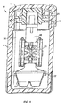
- FIG. 1 is a side sectional view of one embodiment of a disinfection apparatus of the present invention.
- Disinfection apparatus 10 includes container 12 which is adapted to receive a disinfecting solution.
- Container 12 has an end which includes a substantially circular periphery defining an opening which is adapted to receive a lens retaining means.
- Cap 14 is releasably affixed to the open end of container 12 via mating threading 16 on the cap and container.
- Cap 14 has elongated member 18 affixed thereto.
- Elongated member 18 supports article-retaining means 20, catalytic element-retaining means 22, and deformable sealing means 24.
- the catalyst element-retaining means holds catalytic element 26 beneath article-retaining means 20.
- Elongated member 18 extends into cavity 28 defined by container 12 when cap 14 is affixed to the container.
- the deformable sealing means is positioned between cap 14 and article-retaining means 20 to seal cavity 28 from the surroundings, and prevent liquid held within the cavity from leaking from the disinfection apparatus when the apparatus is tilted or turned upside down.
- the deformable sealing means provides a normally closed, substantially liquid-impermeable seal for liquid held within the container.
- the sealing means is at least partially deformable, such that internal gas generated within the container will vent to a point outside the container by at least partially deforming a portion of the sealing means, thereby forming a passageway between a point inside said container to a point outside said container.
- the passageway may include a path through a loosely threaded cup-container connection or openings, such as circular holes, directly through the cap.
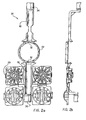
- FIGS. 2a and 2b are side sectional views of one embodiment of an unassembled, molded member which includes article-retaining means 20, catalytic element-retaining means 22, and elongated member 18.
- a catalytic element (not shown in FIGS. 2a and 2b) is inserted into catalytic element-retaining means.
- elongated member 18 is folded at flexible joints 32 so that end 34 is positioned immediately adjacent end 36.
- Ends 34 and 36 are permanently affixed to one another by any means known in the art, including without limitation thereto, use of adhesives, use of pressure affixation methods, use of interference fit designs of the ends, or use of heat sealing methods.
- FIG. 3 is a side sectional view of an alternative molded member to the embodiment shown in FIGS. 2a and 2b. While the embodiment of FIGS. 2a and 2b requires a step of affixing end 34 to end 36 subsequent to molding, the FIG. 3 embodiment is a molded member which does not require a subsequent affixation step to form end 43.
- article-retaining means 20 includes two holders, which are shaped to hold ophthalmic lenses, especially contact lenses.
- Lens holder 38 includes a concave portion 40 and a convex portion 42 connected by a flexible joint 44. In use, a contact lens may be placed in concave portion 40, while convex portion 42 is rotated to a position immediately adjacent concave portion 40.
- concave and convex portions are releasably affixed to one another, e.g., by interference fit or some form of snap fitting, to retain the lens during the disinfection cycle.
- Concave portion 40 and convex portion 42 include openings 46 and 48, respectively, to allow disinfecting solution to pass through to the lens retained therein.
- a catalytic element is inserted into opening 45 of the FIG. 3 embodiment and dropped onto catalytic element-retaining means 41.
- the peripheral rim of the catalytic element-retaining means (See FIG. 7b) rests on the peripheral support of catalytic element-retaining means 41.
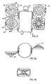
- FIGS. 4a and 4b are bottom views of the molded member of FIG 3.
- FIG. 4a illustrates the molded member with the contact lens holders in an open position, ready to receive contact lenses.
- FIG. 4b illustrates the molded member with contact lens holders releasably affixed to the molded member in a position, which minimizes the cross-sectional area, so that the molded member and contact lenses may be easily inserted into the disinfection container.
- the contact lens holders are affixed to one another by an interference between male affixation member 47 on one contact lens holder and female affixation member 49 on the other contact lens holder.
- the interference fit is preferably sufficiently secure to prevent the consumer from manually separating the contact lens holders, so that the consumer is encouraged to recycle the entire assembly, i.e., molded member and catalytic element, at one time.
- FIGS. 5a and 5b are side and top views of one embodiment of the cap, respectively.
- Cap 50 preferably includes grasping means such as ribs 52, as shown in FIG. 5a, which are raised from the surface of the cap an amount which promotes consumer convenience in grasping the cap.
- the cap also includes venting passageways which are openings extending through the cap.
- Cap 50 includes two substantially circular holes 54 extending through the cap, providing a passageway from a point inside the container to a point outside the container when the cap is affixed to the container.
- FIGS. 5c and 5d are bottom and side sectional views, respectively, of cap 50.
- Cap 50 includes a cylindrical-shaped affixation means 56 which extends substantially perpendicularly from the inside surface of cap 50.
- Affixation means 56 includes a peripheral lip 58 which extends inwardly from the end of the affixation means which is opposite the surface of cap 50.
- the sealing means is connected to the cap by affixation means 56.
- FIGS. 6a, 6b, and 6c are side sectional, top and side views of one embodiment of the sealing means of the present invention.
- Sealing means 60 includes cup-shaped housing 62 having a concave and a convex surface.
- the convex surface includes a substantially flat surface 63 which is adapted to mate with cap 50 and a substantially cylindrical wall 65.
- Two elongated rims 64 and 66 extend peripherally outward and substantially perpendicularly from the cylindrical wall of the convex surface of sealing means 60.
- Sealing means 60 further includes a lip 68 which extends peripherally outward from the cylindrical wall of the convex surface of sealing means 60, at a position between the flat surface 63 and rims 64 and 66.
- Sealing means 60 is formed from a resiliently flexible material so that rims 64 and 66 may be deformed by internal pressure to provide a vent passageway between the sealing means and the container wall for venting. Thus, the seal is not formed within the cap, but is formed by intimate contact between sealing rims 64 and 66 and the container walls. While sealing means 60 may be formed from a wide variety of materials, preferred materials include polypropylene and polyethylene.
- the sealing means of the present invention provides a substantially liquid impermeable seal with the interior of the container walls to form a sealed chamber for liquid retention.
- gas in the sealed chamber causes the internal pressure to reach a predetermined value in excess of the external ambient pressure, the sealing means rims flex or deform, at least partially, to allow gas to pass.
- the gas may then vent outside the apparatus through openings in the cap or through the mating threads of the cap-container connection.
- the sealing means of the present invention presents clear advantages over the prior art.
- One advantage is that the sealing means includes at least two rims, both of which provide protection from solution leakage or spills. If one of the rims becomes damaged (e.g., torn) or inadvertently held open (e.g., by debris on the container walls), the other rim still provides completely independent sealing and venting functions.
- Another advantage of the present sealing means is that the double rim design prevents any leakage from any solution which inadvertently passes the first rim. For example, if the apparatus is placed in a travel container and shaken during travel, increased disinfectant decomposition rates and foaming may result. Alternatively, if the apparatus is placed upside down during the disinfectant decomposition process, solution may conceivably be forced past the first rim. In either of these instances, the second sealing rim provides additional protection to keep the solution from leaking out of the disinfection apparatus.
- the catalytic element includes a thin molded substrate and a catalytic coating deposited on the substrate.
- the substrate is preferably an inexpensive plastic material, such as poly(ethylene terephthalate), also known as PET.
- the preferred catalytic coating is platinum or a platinum-containing alloy, because platinum catalyzes the decomposition of hydrogen peroxide into water and oxygen.
- the coating may be deposited by a number of methods known in the art, including dip coating and ion beam deposition methods.
- a preferred method of coating the substrate material is by ion beam-assisted deposition.
- a preferred catalytic element has a PET substrate, which is coated or impregnated with platinum metal.
- the catalytic element is preferably of a shape, which lends itself to inexpensive and efficient mass production by vacuum forming.
- the catalytic element preferably has a convex surface and a concave surface.
- the catalytic element should have a base portion and a side wall portion which extends from the peripheral edge of the base portion, with the side walls having either a cylindrical or conical shape.
- the catalytic element preferably has protrusions or extensions, which increase surface area without either substantially increasing the volume the element must occupy or substantially increasing the difficulty of manufacture.
- the catalytic element should also be shaped to promote good fluid flow and minimize "dead space" (i.e., areas of little or no flow) during the disinfectant decomposition process. Therefore, the catalytic element preferably includes a plurality of holes therethrough, with the holes being located to facilitate improved flow regimes. Finally, the catalytic element should have a means for affixing the catalytic element to the disinfection apparatus.
- the catalytic element has a truncated cone shape.
- the catalytic element has a circular flat surface with a conical wall extending outwardly from the edge of the circular flat surface.
- the angle which the conical wall extends from the flat surface has an impact on both the flow during the decomposition of the disinfectant and the catalytic metal deposition process. If the angle of the wall is too steep, deposition of metal (e.g., platinum) on the wall is very difficult. On the other hand, angles which are too large (i.e., approaching a flat sheet) tend to cause gas bubbles to remain adhered to the wall during the disinfection process. The adhered bubbles prevent disinfectant from efficiently contacting the catalyst, thereby slowing the decomposition process. Therefore, the angle between the conical portion and flat bottom portion of the catalyst is preferably about 30 to 60 degrees.
- the catalytic coating is preferably only deposited on the inner walls of the catalyst substrate material. Coating only the inner walls of the catalyst substrate ensures that gas from disinfectant decomposition is generated only on the concave interior portion of the catalytic element. A current is then generated as the gas bubbles are released from the interior of the catalytic element and move towards the top of the disinfectant container. Solution from beneath the catalytic element passes through the openings in the bottom of the catalytic element to replace the gas bubbles which are released from the inside. Thus, gas bubbles moving upward in the interior of the container cause an interior upward solution flow and a downward solution flow near the container walls.
- the catalytic element is preferably coated only on the interior surfaces in order to promote good mixing and minimize the time required to decompose the disinfectant.
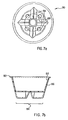
- FIGS. 7a and 7b are bottom and side sectional views of one embodiment of the catalytic element of the present invention.
- Catalytic element 80 has a interior concave surface 82 and an exterior which includes a base portion 84 and walls 86 extending in a conical fashion from bottom 84.
- Catalytic element 80 also includes a plurality of holes 88 through bottom surface 84.
- Bottom surface 84 includes raised portions 90 which add surface area to the catalytic element without adding substantially to the difficulty of manufacturing the catalytic element or to the volume required by the catalytic element when placed in the container.
- Catalytic element 80 also includes rim 92, which extends outwardly along the peripheral edge of the catalytic element. The catalytic element is retained within the assembled elongated member when rim 92 rests within catalytic element-retaining means 22 (See FIG.1).
- the substrate of the catalytic element is a flexible material, which has sufficient rigidity to give the catalytic element a definite shape.
- the substrate is formed in an efficient, inexpensive vacuum forming process.
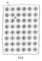
- FIG. 8 is a bottom view of a molded sheet of catalytic element substrates having the shape of the catalytic elements of FIGS. 7a and 7b.
- a plurality of catalytic element 100 are vacuum formed in a sheet of substrate material 102.
- the catalytic element substrates may then be punched out or cut out of the sheet 102.
- the catalytic elements are vacuum formed and coated with catalyst in a semi-batch or continuous process.
- the catalytic element formation process may include the steps of (a) feeding a continous sheet of substrate material into a vacuum forming chamber, (b) vacuum forming a desired cataltyic element shape in the substrate material, (c) feeding the continuous sheet into a coating chamber, (d) coating at least one surface of the shaped catalytic element substrate to form a catalytic element, and (e) removing a catalytic element from the sheet. While all surfaces of the catalytic element may be coated, it is preferably to have only the interior surface of the shaped catalytic element substrate coated with catalyst material.
- affixing components of the disinfecting apparatus to one another may be selected from a wide variety of affixation methods known in the art and described generally herein.
- releasably affixing one component to another refers to the affixing of components in a manner that allows the components to be separated from, and re-affixed to, one another many times without substantially damaging the components or the affixation means.
- Perfectly affixing one component to another refers to methods of affixing components such that separation of the components results in substantial damage to one or more of the components, likely to render the components or affixation means inoperable.
Landscapes
- Chemical & Material Sciences (AREA)
- Health & Medical Sciences (AREA)
- Chemical Kinetics & Catalysis (AREA)
- Animal Behavior & Ethology (AREA)
- Epidemiology (AREA)
- Life Sciences & Earth Sciences (AREA)
- General Health & Medical Sciences (AREA)
- Public Health (AREA)
- Veterinary Medicine (AREA)
- Organic Chemistry (AREA)
- General Chemical & Material Sciences (AREA)
- Materials Engineering (AREA)
- Engineering & Computer Science (AREA)
- Apparatus For Disinfection Or Sterilisation (AREA)
- Eyeglasses (AREA)
Applications Claiming Priority (3)
| Application Number | Priority Date | Filing Date | Title |
|---|---|---|---|
| US515782 | 1995-08-16 | ||
| US08/515,782 US5609837A (en) | 1995-08-16 | 1995-08-16 | Disinfection apparatus |
| EP96810520A EP0761238B1 (de) | 1995-08-16 | 1996-08-07 | Desinfektionsgerät |
Related Parent Applications (1)
| Application Number | Title | Priority Date | Filing Date |
|---|---|---|---|
| EP96810520A Division EP0761238B1 (de) | 1995-08-16 | 1996-08-07 | Desinfektionsgerät |
Publications (2)
| Publication Number | Publication Date |
|---|---|
| EP1249276A2 true EP1249276A2 (de) | 2002-10-16 |
| EP1249276A3 EP1249276A3 (de) | 2002-12-18 |
Family
ID=24052716
Family Applications (2)
| Application Number | Title | Priority Date | Filing Date |
|---|---|---|---|
| EP96810520A Expired - Lifetime EP0761238B1 (de) | 1995-08-16 | 1996-08-07 | Desinfektionsgerät |
| EP02010368A Withdrawn EP1249276A3 (de) | 1995-08-16 | 1996-08-07 | Katalytisches Element zur Desinfektion von z. B. Kontaktlinsen |
Family Applications Before (1)
| Application Number | Title | Priority Date | Filing Date |
|---|---|---|---|
| EP96810520A Expired - Lifetime EP0761238B1 (de) | 1995-08-16 | 1996-08-07 | Desinfektionsgerät |
Country Status (17)
| Country | Link |
|---|---|
| US (3) | US5609837A (de) |
| EP (2) | EP0761238B1 (de) |
| JP (1) | JP3862786B2 (de) |
| KR (1) | KR970009814A (de) |
| CN (1) | CN1128639C (de) |
| AR (1) | AR003295A1 (de) |
| AT (1) | ATE225190T1 (de) |
| AU (1) | AU728867B2 (de) |
| BR (1) | BR9603440A (de) |
| CA (1) | CA2183308C (de) |
| DE (1) | DE69624058T2 (de) |
| ES (1) | ES2185755T3 (de) |
| IL (1) | IL119039A0 (de) |
| NO (1) | NO963417L (de) |
| NZ (1) | NZ299167A (de) |
| TW (1) | TW373089B (de) |
| ZA (1) | ZA966924B (de) |
Families Citing this family (23)
| Publication number | Priority date | Publication date | Assignee | Title |
|---|---|---|---|---|
| US6132825A (en) * | 1996-07-12 | 2000-10-17 | Tetra Laval Holdings & Finance, Sa | Sterilant degrading polymeric material |
| NO304355B1 (no) * | 1997-02-20 | 1998-12-07 | Sinvent As | Multi-autoklav for metodisk, automatisert syntese av zeolitter og andre forbindelser |
| DE19757356C1 (de) * | 1997-12-22 | 1999-07-01 | Mdle Medical Device Lab Europ | Vorrichtung zur Pflege von Kontaktlinsen |
| US5950644A (en) * | 1998-02-05 | 1999-09-14 | Brewer; Edward N. | Denture cleanser |
| US6581761B1 (en) * | 1999-11-02 | 2003-06-24 | Bausch & Lomb Incorporated | Mesh tray assembly |
| US20040136864A1 (en) * | 2003-01-10 | 2004-07-15 | Barham William L. | Treatment of dentures at elevated pressure |
| JP4687860B2 (ja) * | 2003-06-27 | 2011-05-25 | 東洋製罐株式会社 | コンタクトレンズ洗浄容器及び容器キャップ |
| GB2405219A (en) * | 2003-08-18 | 2005-02-23 | Charles Ifejika | Cleaning device for contact lenses |
| BRPI0607719A2 (pt) * | 2005-02-17 | 2009-10-06 | Oxyband Technologies Inc | método e aparelho para suprir gás para uma área |
| US8353305B1 (en) | 2007-01-24 | 2013-01-15 | William L Barham | Pressure vessel for treating dentures |
| EP2114191B1 (de) * | 2007-02-07 | 2013-09-11 | Atrion Medical Products, Inc. | Verbessertes kontaktlinsengehäuse |
| US8141699B2 (en) * | 2008-02-07 | 2012-03-27 | Atrion Medical Products, Inc. | Contact lens case |
| US8329098B2 (en) * | 2009-03-16 | 2012-12-11 | Atrion Medical Products, Inc. | Additive effect enhanced hydrogen peroxide disinfection method and apparatus |
| US8038939B2 (en) * | 2009-06-09 | 2011-10-18 | Atrion Medical Products, Inc. | Method and devices for improved disinfection process |
| US20120085662A1 (en) * | 2009-07-10 | 2012-04-12 | Menicon Co., Ltd. | Case for sterilizing contact lenses |
| CA2775969C (en) * | 2009-11-17 | 2016-12-20 | Novartis Ag | A hydrogen peroxide solution and kit for disinfecting contact lenses |
| EP2544725A1 (de) * | 2010-03-08 | 2013-01-16 | Novartis AG | Aktives sauerstoffdesinfektionssystem und anwendung davon |
| CA2826776A1 (en) | 2011-02-23 | 2012-08-30 | Novabay Pharmaceuticals, Inc. | Contact lens cleaning system with monitor |
| JP2013042952A (ja) * | 2011-08-24 | 2013-03-04 | Jms Co Ltd | キャップおよびコネクターシステム |
| US10398799B2 (en) | 2014-04-03 | 2019-09-03 | Novartis Ag | System for disinfecting contact lenses |
| JP6273039B2 (ja) | 2014-04-03 | 2018-01-31 | ノバルティス アーゲー | コンタクトレンズを消毒および洗浄するための電気化学的システム |
| JP6710409B2 (ja) * | 2016-03-09 | 2020-06-17 | 国立大学法人大阪大学 | コンタクトレンズ消毒用過酸化水素の分解触媒およびその製造方法 |
| CN107741654B (zh) * | 2017-11-13 | 2019-10-11 | 枣庄市山亭区微乐园地瓜种植专业合作社 | 隐形眼镜清洗器 |
Family Cites Families (40)
| Publication number | Priority date | Publication date | Assignee | Title |
|---|---|---|---|---|
| US3005455A (en) * | 1955-06-24 | 1961-10-24 | Baxter Laboratories Inc | Container closure |
| GB893987A (en) * | 1958-11-07 | 1962-04-18 | Napier & Son Ltd | Catalysts for decomposing hydrogen peroxide |
| US3279995A (en) * | 1963-05-31 | 1966-10-18 | Allen F Reid | Shaped pellets |
| JPS4825495U (de) * | 1971-07-31 | 1973-03-26 | ||
| US3912451A (en) * | 1973-06-04 | 1975-10-14 | Warner Lambert Co | Method for removing hydrogen peroxide from soft contact lenses |
| US3910850A (en) * | 1973-12-19 | 1975-10-07 | Grace W R & Co | Contoured monolithic substrate |
| US4011941A (en) * | 1975-04-28 | 1977-03-15 | Warner-Lambert Company | Contact lens capsule |
| US4294801A (en) * | 1978-03-24 | 1981-10-13 | Nippon Soken, Inc. | Gas component detector |
| DE3109921A1 (de) * | 1981-03-14 | 1982-09-23 | Wella Ag, 6100 Darmstadt | Zwei-komponenten-verpackung fuer schuettbare medien |
| US4396583A (en) * | 1981-08-14 | 1983-08-02 | American Optical Corporation | Device for single solution contact lens sterilization |
| US4637919A (en) * | 1984-11-05 | 1987-01-20 | Ryder International Corporation | Lens disinfecting appliance with improved venting feature |
| US4750610A (en) * | 1986-12-29 | 1988-06-14 | Ryder International Corporation | Lens case with pressure sensitive venting system |
| US4807750A (en) * | 1987-10-28 | 1989-02-28 | Ryder International Corporation | Latching structure for contact lens holder |
| US4889693A (en) * | 1988-01-22 | 1989-12-26 | Ciba-Geigy Corporation | Apparatus for venting of gases from contact lens cases |
| US5059402A (en) * | 1988-08-12 | 1991-10-22 | Seamons Kenneth R | Contact lens disinfection unit |
| US4981657A (en) * | 1988-09-09 | 1991-01-01 | Ryder International Corporation | Contact lens case with raised, protective ribs |
| US4956156A (en) * | 1988-11-07 | 1990-09-11 | Ryder International Corporation | Pressure venting system for lens cases |
| US4996027A (en) * | 1989-04-07 | 1991-02-26 | Ciba Vision Corporation | Contact lens case having pressure venting gasket |
| US4890729A (en) * | 1989-04-25 | 1990-01-02 | Ryder International Corporation | Lens retaining apparatus |
| US5196174A (en) * | 1989-06-09 | 1993-03-23 | Ciba Vision Corporation | Apparatus for sterilizing contact lenses |
| JP2660453B2 (ja) * | 1989-06-09 | 1997-10-08 | シーバ ヴィジョン コーポレーション | コンタクトレンズの殺菌装置 |
| US5468448A (en) * | 1989-12-28 | 1995-11-21 | Ciba-Geigy Corporation | Peroxide disinfection method and devices therefor |
| ES2022020A6 (es) * | 1990-05-03 | 1991-11-16 | Dirygesa Sl | Procedimiento para desinfectar lentes de contacto. |
| US5077258A (en) * | 1990-06-15 | 1991-12-31 | Flex Products, Inc. | Vapor deposited metal catalytic film, process for making the same and liquid container with the film |
| US5089240A (en) * | 1990-08-22 | 1992-02-18 | Ciba Vision Corporation | Catalytic lens sterilizing system |
| DE4029749A1 (de) * | 1990-09-20 | 1992-03-26 | Schwaebische Huettenwerke Gmbh | Filter |
| US5250266A (en) * | 1990-11-30 | 1993-10-05 | Ciba Vision Corporation | Contact lens case venting system |
| WO1992009942A1 (en) * | 1990-11-30 | 1992-06-11 | Ciba Vision Corporation | Contact lens case venting system |
| US5143104A (en) * | 1990-12-07 | 1992-09-01 | Allergan, Inc. | Vented apparatus for storing and cleaning an element |
| AU1196692A (en) * | 1991-01-15 | 1992-08-27 | Ciba Vision Corporation | Improved method and apparatus for the sterilization of contact lenses |
| GB9104704D0 (en) * | 1991-03-06 | 1991-04-17 | Lawson Mardon M I Ltd | Cap,sealingly engageable with a container |
| US5275287A (en) * | 1991-04-10 | 1994-01-04 | Mcg Closures Ltd. | Closures |
| US5270002A (en) * | 1991-10-03 | 1993-12-14 | Allergan, Inc. | Apparatus and method useful in disinfecting contact lenses |
| EP0542686A1 (de) * | 1991-11-13 | 1993-05-19 | Ciba-Geigy Ag | Verfahren und Behälter für die Sterilisation und Desinfektion |
| US5346083A (en) * | 1992-06-02 | 1994-09-13 | The Board Of Regents Of The University Of Nebraska | Container and/or closure therefor |
| JPH067416A (ja) * | 1992-06-25 | 1994-01-18 | Matsushita Electric Works Ltd | 消臭剤 |
| US5388686A (en) * | 1993-02-02 | 1995-02-14 | Ryder International Corporation | Lens case for contact lens disinfecting system |
| US5340583A (en) * | 1993-05-06 | 1994-08-23 | Allergan, Inc. | Antimicrobial lenses and lens care systems |
| DK171504B1 (da) * | 1993-10-29 | 1996-12-02 | Bruun Jensen Joergen | Apparat til at desinficere kontaktlinser |
| KR980000475A (ko) * | 1996-06-04 | 1998-03-30 | 로트 베른하르트 엠. 발덱 베르너 | 개량된 배기 수단이 구비된 콘택트렌즈 소독 장치 |
-
1995
- 1995-08-16 US US08/515,782 patent/US5609837A/en not_active Expired - Lifetime
-
1996
- 1996-02-29 TW TW085102399A patent/TW373089B/zh active
- 1996-07-17 US US08/682,212 patent/US5609264A/en not_active Expired - Lifetime
- 1996-07-17 US US08/682,450 patent/US5958351A/en not_active Expired - Lifetime
- 1996-08-07 AT AT96810520T patent/ATE225190T1/de not_active IP Right Cessation
- 1996-08-07 DE DE69624058T patent/DE69624058T2/de not_active Expired - Lifetime
- 1996-08-07 ES ES96810520T patent/ES2185755T3/es not_active Expired - Lifetime
- 1996-08-07 EP EP96810520A patent/EP0761238B1/de not_active Expired - Lifetime
- 1996-08-07 EP EP02010368A patent/EP1249276A3/de not_active Withdrawn
- 1996-08-08 IL IL11903996A patent/IL119039A0/xx unknown
- 1996-08-08 JP JP20963796A patent/JP3862786B2/ja not_active Expired - Lifetime
- 1996-08-09 AU AU62005/96A patent/AU728867B2/en not_active Ceased
- 1996-08-09 KR KR1019960033116A patent/KR970009814A/ko not_active Ceased
- 1996-08-14 NZ NZ299167A patent/NZ299167A/en unknown
- 1996-08-14 CA CA002183308A patent/CA2183308C/en not_active Expired - Fee Related
- 1996-08-15 BR BR9603440A patent/BR9603440A/pt not_active Application Discontinuation
- 1996-08-15 ZA ZA966924A patent/ZA966924B/xx unknown
- 1996-08-15 CN CN96111840A patent/CN1128639C/zh not_active Expired - Fee Related
- 1996-08-15 NO NO963417A patent/NO963417L/no not_active Application Discontinuation
- 1996-08-16 AR ARP960104030A patent/AR003295A1/es unknown
Also Published As
| Publication number | Publication date |
|---|---|
| EP0761238A3 (de) | 1997-05-02 |
| MX9603438A (es) | 1997-07-31 |
| JP3862786B2 (ja) | 2006-12-27 |
| AU6200596A (en) | 1997-02-20 |
| NO963417L (no) | 1997-02-17 |
| NZ299167A (en) | 1998-11-25 |
| CA2183308C (en) | 2008-09-30 |
| AU728867B2 (en) | 2001-01-18 |
| JPH09103470A (ja) | 1997-04-22 |
| EP1249276A3 (de) | 2002-12-18 |
| IL119039A0 (en) | 1996-11-14 |
| US5609264A (en) | 1997-03-11 |
| EP0761238A2 (de) | 1997-03-12 |
| TW373089B (en) | 1999-11-01 |
| KR970009814A (ko) | 1997-03-27 |
| BR9603440A (pt) | 1998-05-12 |
| ATE225190T1 (de) | 2002-10-15 |
| ES2185755T3 (es) | 2003-05-01 |
| DE69624058D1 (de) | 2002-11-07 |
| ZA966924B (en) | 1997-05-16 |
| CA2183308A1 (en) | 1997-02-17 |
| CN1128639C (zh) | 2003-11-26 |
| US5958351A (en) | 1999-09-28 |
| CN1145256A (zh) | 1997-03-19 |
| AR003295A1 (es) | 1998-07-08 |
| DE69624058T2 (de) | 2003-11-20 |
| US5609837A (en) | 1997-03-11 |
| NO963417D0 (no) | 1996-08-15 |
| EP0761238B1 (de) | 2002-10-02 |
Similar Documents
| Publication | Publication Date | Title |
|---|---|---|
| CA2183308C (en) | A sealing and venting component for an apparatus which generates an internal gas | |
| US4750610A (en) | Lens case with pressure sensitive venting system | |
| US4637919A (en) | Lens disinfecting appliance with improved venting feature | |
| JP3942665B2 (ja) | 改良された排気手段を有するコンタクトレンズ消毒装置 | |
| US5972292A (en) | Sealing and venting system for oxidative disinfection of contact lenses | |
| US4956156A (en) | Pressure venting system for lens cases | |
| US8757367B2 (en) | Pressure-venting container for disinfection and storage of contact lenses | |
| JPH0226981B2 (de) | ||
| WO1992010110A1 (en) | Vented apparatus for storing and cleaning an element | |
| AU733486B2 (en) | Improved contact lens disinfecting device and disinfection system | |
| AU655955B2 (en) | Contact lens case venting system | |
| EP0800780B1 (de) | Vorrichtung und Verfahren zur Behandlung von Gegenständen in einer Lösung mit Brausetabletten | |
| JP6385594B2 (ja) | コンタクトレンズの消毒および保管のための圧力放出容器 | |
| MXPA96003438A (en) | Disinfection apparatus | |
| US9439990B2 (en) | Leak-proof contact lens container | |
| HK1019307B (en) | Contact lens disinfecting device | |
| WO2010111551A2 (en) | Methods and apparatus for improved cleaning and disinfecting of items |
Legal Events
| Date | Code | Title | Description |
|---|---|---|---|
| PUAI | Public reference made under article 153(3) epc to a published international application that has entered the european phase |
Free format text: ORIGINAL CODE: 0009012 |
|
| 17P | Request for examination filed |
Effective date: 20020507 |
|
| AC | Divisional application: reference to earlier application |
Ref document number: 761238 Country of ref document: EP |
|
| AK | Designated contracting states |
Kind code of ref document: A2 Designated state(s): AT BE CH DE DK ES FI FR GB GR IE IT LI LU NL PT SE |
|
| PUAL | Search report despatched |
Free format text: ORIGINAL CODE: 0009013 |
|
| AK | Designated contracting states |
Kind code of ref document: A3 Designated state(s): AT BE CH DE DK ES FI FR GB GR IE IT LI LU NL PT SE |
|
| RAP1 | Party data changed (applicant data changed or rights of an application transferred) |
Owner name: NOVARTIS PHARMA GMBH Owner name: NOVARTIS AG |
|
| RAP1 | Party data changed (applicant data changed or rights of an application transferred) |
Owner name: NOVARTIS PHARMA GMBH Owner name: NOVARTIS AG |
|
| 17Q | First examination report despatched |
Effective date: 20030718 |
|
| AKX | Designation fees paid |
Designated state(s): AT BE CH DE DK ES FI FR GB GR IE IT LI LU NL PT SE |
|
| STAA | Information on the status of an ep patent application or granted ep patent |
Free format text: STATUS: THE APPLICATION IS DEEMED TO BE WITHDRAWN |
|
| 18D | Application deemed to be withdrawn |
Effective date: 20040629 |