EP1249311A2 - Spannvorrichtung - Google Patents
Spannvorrichtung Download PDFInfo
- Publication number
- EP1249311A2 EP1249311A2 EP02007636A EP02007636A EP1249311A2 EP 1249311 A2 EP1249311 A2 EP 1249311A2 EP 02007636 A EP02007636 A EP 02007636A EP 02007636 A EP02007636 A EP 02007636A EP 1249311 A2 EP1249311 A2 EP 1249311A2
- Authority
- EP
- European Patent Office
- Prior art keywords
- teeth
- toothing
- gear
- bevel gear
- adjusting
- Prior art date
- Legal status (The legal status is an assumption and is not a legal conclusion. Google has not performed a legal analysis and makes no representation as to the accuracy of the status listed.)
- Withdrawn
Links
Images






Classifications
-
- B—PERFORMING OPERATIONS; TRANSPORTING
- B25—HAND TOOLS; PORTABLE POWER-DRIVEN TOOLS; MANIPULATORS
- B25B—TOOLS OR BENCH DEVICES NOT OTHERWISE PROVIDED FOR, FOR FASTENING, CONNECTING, DISENGAGING, OR HOLDING
- B25B5/00—Clamps
- B25B5/06—Arrangements for positively actuating jaws
Definitions
- the invention relates to a clamping device.
- a clamping device Such jigs are in industrial use in particular for the mutual bracing of two parts, for example two sheets, used.
- the two clamped parts can then together connected, for example welded.
- the clamping device a clamping lever, which can be pivoted around the housing of the clamping device can.
- the tensioning lever can be loaded from an open position a suitable torque of, for example, 100 to 150 Nm against one anvil on the housing side.
- the clamping lever is, for example, a Toggle lever turned, which is operated via a hydraulic or pneumatic cylinder becomes.
- the conventional clamping device must be a hydraulic pump or a Have a compressor that pressurizes and transports the required fluid. The This makes the clamping device relatively unwieldy and heavy, or it must be used with a corresponding supply facility can be connected.
- the invention has for its object improvements over the prior art To create technology and in particular to create a jig that is versatile Use, in particular also setting different clamping angles, and ensures safe handling.
- the tensioning device according to the invention is intended in particular be small and preferably relatively inexpensive to manufacture. hereby should in particular a quick, easy and easy handling of the clamping device and accessibility of hard-to-reach places, for example through narrower openings and in a limited space.
- a tensioning device with a mechanical reduction gear is thus according to the invention created.
- this mechanical reduction gear minimizes the required energy expenditure.
- the invention Reduction gear on self-blocking, so that due to the elasticity of the pressed-in parts or a further handling or welding generated restoring moments be blocked.
- the clamping arm in the operating position means with jammed or clamped parts, even over a longer period can be held safely without additional energy expenditure.
- a reduction gear is used which is very small and thus ensures a compact design of a tensioning device according to the invention.
- additional units for example a hydraulic pump or a compressor, can be dispensed with, the tensioning device according to the invention on the one hand inexpensive and on the other hand light and light manageable.
- the mechanical reduction gear allows adjustment to any angle within the maximum permissible swivel angle.
- the tensioning device according to the invention with partially folded tension arm which only has a small opening angle opposite the anvil, through smaller openings, for example that Windows of a motor vehicle body, move and a safe even in confined spaces Two parts can be guaranteed.
- a reduction gear is used in which two planetary gear systems are coupled together.
- the two have a similar structure
- Orbital gear systems show a difference in the number of teeth according to the invention can be chosen in particular relatively small. This will detune the allows two gear systems to each other, which by coupling to a very low Relative rotation of one system leads to the other, creating a very high reduction can be achieved.
- the coupling of the two epicyclic gear systems can, on the one hand, be done by means of epicyclic gearwheels with different gearing areas. Such a coupling is particularly useful when using bevel gears, with one Adjustment gear a radially inner and a radially outer bevel gear area different are interlocked. On the other hand, a coupling can also be via the planet gears take place that have different gearing areas. This is particularly so sensible when using ring gears as adjusting gears.
- a relative adjustment the adjustment gears or hollow gears with internal teeth is achieved by this are connected via common planetary gears, which are driven by a drive shaft become.
- the planetary gears here have axially separated areas on each of which an area with one of the two adjustment gears with internal teeth is engaged.
- two can be on the housing side fixed ring gears, i.e. a first and a third ring gear with first and third internal teeth, are used, between which the second ring gear with second internal teeth is rotatably arranged.
- a small angle gear is advantageously used formed, in which also the motor in a housing directly on the clamping device can be accommodated.
- two Gear systems formed which differ in the number of teeth, with small Differences in the number of teeth a very high reduction can be achieved.
- the adjusting gears generally have at least two radially offset, preferably adjacent bevel gear areas.
- the drive bevel gear is here with the preferably radially outer bevel gear region Adjusting gear engaged.
- the adjustment gears are coupled via common Orbital gears, each with the other, preferably radially inner bevel area each adjusting gear are engaged.
- the planetary gears with circular bevel gears are each rotatable on a pin one to the adjustment gears coaxial output shaft. This creates a radially outer gear system Drive bevel gear and radially outer bevel gear areas and a radial inner gear system made of circular bevel gears and radially inner bevel gear areas formed, the gear systems with each other via the adjusting gears are coupled.
- idler gears or gear wheels can be used to support the radially outer areas of the adjustment gears can be used. Due to the difference in the number of teeth the gear systems are advantageously the angular distances of either the radially inner Pin axles with incorporated planet gears or the radially outer idler gears with drive gear somewhat uneven. For example, if you use six Orbiting gears, five idler gears (and a drive gear) can thus outer angular distances and / or the inner angular distances of the pin axes in each case deviate somewhat from 60 °, so that an engagement in the inner or outer gear systems is guaranteed.
- the output shaft is tapped, for example, via a form-fitting holder through the tension arm, for example via a fork, which has a square area of the Output shaft grips.
- the conical toothing areas advantageously have a palloidal toothing on.
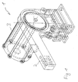
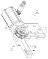
- a tensioning device 1 has a housing 3 for receiving a motor, in particular an electric motor and a tensioning lever 2 which can be pivoted about the housing 3 on.
- the housing can be attached in a suitable manner via a lower flange Example are screwed.
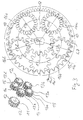
- FIG. 2 are on the cylindrical housing 3, for example as a pressed sheet metal part manufactured third ring gear 5 with third internal teeth 7, a second ring gear 9 with second internal toothing 10 and rigidly attached clamping lever 2, which is on a bearing 18 is arranged rotatably or pivotably, and a first ring gear 4 with first internal teeth 6, which can be identical to the third ring gear 5 and also as Pressed sheet metal part can be attached in the axial direction.
- the attachment can for example by a clamp 19 around the first and third ring gear and by means of screws, Bolts and similar fastenings are made. These parts become rigid with this connected to the housing 3, the second ring gear 9 relative to this on the housing side Arrangement is pivotable.
- planetary gears 13a to 13e are distributed in the circumferential direction, preferably evenly distributed, provided in the internal teeth.
- the single ones Orbiting gears 13a to 13e are preferably composed of at least three individual gears four single gears, put together, the single gears together for example glued, welded, screwed, keyed or designed as a one-piece injection molded part can be.
- the planetary gears each have a first external toothing area axially on the outside 15 and a third external toothing area 14, which advantageously can be arranged without an angular offset to one another.
- the first external gear area 15 is in engagement with the first internal toothing 6, and the third external toothing area 14 is in engagement with the third internal toothing 7 3, for example, formed from two individual gears placed one against the other, middle second external tooth area 16 of each of the planet gears is in engagement with the second internal toothing 10.
- a drive gear 11 with drive teeth or drive teeth 12 is coaxial arranged to the ring gears, the drive teeth 12 according to Figures 3, 2nd can have axially separated regions, each with the first and third External gear area are engaged. There can be a space between these areas be provided so that there is no interaction with the second external tooth area takes place.
- the drive gear 11 is torsionally rigid with a drive shaft 8 connected, for example via a suitable square area on the drive shaft and a suitable slot 17 can be ensured in the drive gear 11.
- a first gear system that of the third gear system corresponds
- a second gear system via the common planet gears rigidly coupled.
- a drive can also via the middle second external toothing areas of the planetary gears.
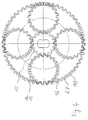
- the first and third external tooth area each have the same number of teeth as the second external tooth area. This is particularly so can be seen from the gear 13c, in which the individual gears or external toothing areas are attached to each other without angular offset; this planet gear can thus be made in one piece.
- the angular misalignment of the first (and third) external toothing area changes all around with respect to the second external tooth area 16, preferably proportional to the angular position about the common axis.
- the angular offset is thus for gear 13d and gear 13b each 1/5 of an angular distance between two teeth the planet gears.
- the angular misalignment for the planetary gears 13e, 13a is corresponding to +/- 2/5 of the angular distance. This will make it more even Intervention of the different external toothing areas in the respective internal toothing and ensured in the drive teeth 12.
- a correction is made - differently than with conventional gear systems - not about the module size or the division of labor of the various Gear systems, but about the angular misalignment.
- such an adjustment of the angular offset is also carried out in gear systems in which the number of teeth of the different external toothing areas is unequal are, in this case the number of teeth of the first internal toothing and second Internal teeth can be the same or different.
- the planetary gears can in particular achieve a small difference in the number of teeth, which is advantageously only 1 or 2. This can result in very high Reductions and yet a smooth gear system are made possible.
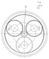
- the number of teeth of the different external toothing areas is 12 each, the number of teeth of the internal toothing is 39 or 40 and the number of teeth of the drive toothing is 16, which leads to a reduction of 137.5 can be achieved.
- a ratio i 206.666 is achieved in which the number of teeth of the first and second external tooth areas 10 and 9, the number of teeth of the drive toothing 15 and the number of teeth of the first and second internal gears are 35 and 31 respectively
- a translation i 759.6 is achieved, by the number of teeth of the internal gears 102 and 103, the number of teeth of the different drive toothing areas are equal to 43, with the gear 13c again covering the external toothing areas without angular misalignment and at the other two gears 13a, 13b an angular offset of +/- 1/3 of a tooth is present.
- the number of teeth of the drive gear is 16, which means a high reduction is guaranteed.
- a ratio i 382.5 is obtained with teeth 16 of the external teeth 20 and 18 of the external toothing areas, 56 and 51 of the internal toothing.
- the angular offset of the individual external toothing areas adapted to each other to the position of the internal gears, so that the Angular misalignment advantageously evenly from the planet gear to the next planet gear changes, especially linear changes.
- a tensioning lever 32 is positioned opposite a housing 33 pivoted.
- the tensioning lever 32 can be guided against an anvil 52 and pick up metal sheets to be pressed in between.
- a Swivel range of, for example, 180 ° or more can be achieved, with a safe Position is ensured in every pivot angle, as is also the case with the first embodiment the case is.
- first adjusting gear 34 has a first bevel gear 36.
- first bevel gear 36 has a radial inner and a radially outer region 36, 37 formed with uniform bevel gear 36.
- a second adjusting gear 35 has a second radially outer bevel gear region 38 and a second radially inner bevel gear region 39, the are shown separately and actually only for the sake of clarity in the exploded view are rigidly connected.
- the two second bevel gear areas 38, 39 have different numbers of teeth and are therefore not as uniform Conical gear area formed.
- the two adjustment gears are on a common one Axis arranged with mutually facing bevel areas.
- a drive bevel gear 48 is located on a drive shaft 43 mounted on the housing side formed, which is in engagement with the radially outer bevel gear areas. in this connection are distributed in the circumferential direction further intermediate gears 49 with intermediate gear bevel gears 50 only to prevent tilting moments, that is, as idler gears or set wheels.
- Axles 44 of these intermediate wheels 50 are - like the drive shaft 43 - stored in round recesses 52 of a housing-side receptacle 53, 8 formed by two interconnected shells 53a, 53b can be.
- the drive shaft 43 is perpendicular to the axis of the adjusting gears arranged.
- a radially inner gear system formed, in which an output shaft 45 is arranged coaxially to the adjusting gears 34, 35 and, for example as shown in the figure, by both adjusting gears can extend through.
- an output shaft 45 is arranged coaxially to the adjusting gears 34, 35 and, for example as shown in the figure, by both adjusting gears can extend through.
- Orbital gears 41 are rotatably mounted on the pin axes 40 and held captive radially outwards by locking washers 54.
- the planet gears have revolving bevel gears 42 which are connected to the two radially inner bevel gearing regions 39, 37 of the adjusting gears are engaged and a radially inner Form gear system.
- the aligned arrangement shown in Figures 8, 9 and 10 Pin axes 40 and axes 44 are shown here only by way of example and at random, since the orbital movements of these systems are separate and the adjustment gears are not included the intermediate wheels are connected.
- the two radially inner conical tooth areas and / or the two radially outer bevel gear areas have different numbers of teeth.
- the first radially outer and inner bevel tooth regions uniform with the same number of teeth and the second bevel gear areas 38, 39 formed with different numbers of teeth.
- the adjusting gears 34, 35 lead relative to the between drive shaft lying on the housing side has an opposite rotational movement by. If the number of teeth in the two outer bevel gear areas is the same, the adjustment gears rotate mutually at the same speed. Are these teeth numbers unequal, the adjustment gear rotates, the outer bevel gear area of which is larger Has the number of teeth, correspondingly slower.
- the planetary gears also lead an opposite rotational movement with respect to the drive shaft lying between them by. With the same number of teeth in the inner bevel gear areas, the adjusting gears turn also in opposite directions to the planetary gears at the same speed, if the number of teeth is unequal, they rotate asymmetrically.
- both the two inner bevel gear areas and the two outer Conical tooth areas would have the same number of teeth, would Orbital gears - like the drive shaft and the idler gears - only as gear wheels rotate around their own axes and therefore no orbital movement around the common one Execute axis. Due to the asymmetrical difference in the number of teeth between the inner and outer bevel gear system however, the planet gears become an orbital motion around the common one Axis forced, which ensures a high reduction.
- the intermediate gears which are preferably used according to the invention are in the receptacle 53 in the embodiment shown with an uneven angular distance from one another appropriate. So they are not evenly spaced from each other by 60 °, but appropriately offset from each other, so that a good intervention guaranteed each intermediate gear in the radially outer bevel gear areas becomes. This allows angles of, for example, +/- 59.14 °, +/- 118.28 ° and 177.42 ° result, whereby these intermediate wheels or clutch wheels a safe engagement and ensure support against tilting moments.
- the uneven angular distances on the pin axes 40 or the planet gears is set.
- the uneven is attached radially on the outside.
- the recesses 52 in the receptacle 53 also attached accordingly at uneven angular intervals.
- the receptacles 53a, 53b are mounted in shells 54 on the housing, which are together and can be screwed together with the housing 33.
- the tension lever 32 grips a square area 46 of the output shaft 45 with a fork 57 and can thus be swiveled safely, with high reduction and with self-blocking.
- a base clamp can also be created with the gears shown above be, in which a clamping arm movable in an arcuate path, preferably is translationally movable.
- FIGS shown with the bevel gear already explained above.
- a coupling piece 60 is rotatably attached.
- An eccentric extension 61 is formed on the coupling piece, which extends into a recess 64 engages the tension arm.
- the tension arm 62 is slidable in a recess 65 of a receiving part 66 and can therefore be a depending on the design of the recess Carry out a wobble movement or a linear, inclined movement.
- a hook-like End 63 of the tension arm 62 can thus be used for tensioning z.
Landscapes
- Engineering & Computer Science (AREA)
- Mechanical Engineering (AREA)
- Retarders (AREA)
- Pressure Welding/Diffusion-Bonding (AREA)
Abstract
- eine Antriebsverzahnung (12, 48) aufweisende Antriebswelle (8, 43),
- ein erstes Verstellzahnrad (4, 34) mit mindestens einem ersten Verstellverzahnungsbereich (6, 36, 37),
- ein zweites Verstellzahnrad (9, 35) mit mindestens einem zweiten Verstellverzahnungsbereich (10, 38, 39),
- mehrere Umlaufzahnräder (13a-e, 41), die in Eingriff mit den mindestens zwei Verstellzahnrädern sind,
Description
- Figur 1 -
- eine perspektivische Ansicht einer Spannvorrichtung gemäß einer ersten Ausführungsform der Erfindung;
- Figur 2 -
- eine Explosionsansicht der Vorrichtung aus Figur 1;
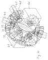
- Figur 3 -
- eine Detailansicht des Zahnradsystems aus Figur 2;
- Figur 4 -
- eine Detailansicht des Zahnradsystems einer abgewandelten Ausführungsform mit anderen Zähnezahlen und anderer Übersetzung;
- Figur 5 -
- eine weitere abgewandelte Ausführungsform mit anderen Zähnezahlen und anderer Übersetzung;
- Figur 6 -
- eine Spannvorrichtung gemäß einer weiteren Ausführungsform der Erfindung unter Verwendung eines Winkelgetriebes;
- Figur 7 -
- eine Darstellung der Spannvorrichtung aus Figur 6 bei verschiedenen Schwenkwinkeleinstellungen;
- Figur 8 -
- eine Explosionsdarstellung der Spannvorrichtung aus Figur 6, 7;
- Figur 9 -
- Detailvergrößerungen des Getriebes aus Figur 8;
- Figur 10 -
- eine weitere Detailvergrößerung des Getriebes aus Figur 8, 9;
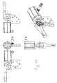
- Figur 11 -
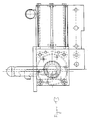
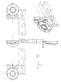
- verschiedene Ansichten der Spannvorrichtung aus Figur 6;
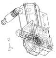
- Figur 12 -
- eine perspektivische Ansicht einer Spannvorrichtung gemäß einer weiteren Ausführungsform der Erfindung;
- Figur 13 -
- eine teilweise auseinandergezogene Darstellung der Spannvorrichtung aus Figur 12;
- Figur 14 -
- verschiedene Ansichten der Spannvorrichtung aus Figur 12;
- Figur 15 -
- Ansichten eines Gehäuseteils der Vorrichtung von Figur 12, 13;
- Figur 16, 17 -
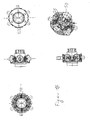
- verschiedene Ansichten des Getriebes der Spannvorrichtung aus Figur 12;
- Figur 18 -
- den Spannarm der Spannvorrichtung aus Figur 12.
Claims (15)
- Spannvorrichtung, mit einem Spannarm (2, 32), der von einer Abtriebswelle eines mechanischen Untersetzungsgetriebes antreibbar ist, das aufweist:wobei ein erster Verstellverzahnungsbereich des ersten Verstellzahnrades und ein zweiter Verstellverzahnungsbereich des zweiten Verstellzahnrades unterschiedliche Zähnezahlen aufweisen und/oder mit den ersten und zweiten Verstellverzahnungsbereichen in Eingriff befindliche Umlaufverzahnungsbereiche unterschiedliche Zähnezahlen aufweisen.eine Antriebsverzahnung (12, 48) aufweisende Antriebswelle (8, 43),ein erstes Verstellzahnrad (4, 34) mit mindestens einem ersten Verstellverzahnungsbereich (6; 36, 37),ein zweites Verstellzahnrad (9, 35) mit mindestens einem zweiten Verstellverzahnungsbereich (10; 38, 39),mehrere Umlaufzahnräder (13a-e, 41), die in Eingriff mit den mindestens zwei Verstellzahnrädern sind,
- Spannvorrichtung nach Anspruch 1, dadurch gekennzeichnet, dass der erste Verstellverzahnungsbereich als erste Innenverzahnung (6) und der zweite Verstellverzahnungsbereich als zweite Innenverzahnung (10) ausgebildet ist,
die Antriebswelle (8) konzentrisch zu dem ersten Verstellzahnrad (4) und dem zweiten Verstellzahnrad (9) angeordnet ist, und die Antriebswellenverzahnung als Wellenaußenverzahnung (12) ausgebildet ist,
die Umlaufzahnräder (13a-e) mindestens zwei axial zueinander versetzte Außenverzahnungsbereiche (14, 15, 16) aufweisen,
die erste Innenverzahnung (6) in Eingriff mit einem ersten Außenverzahnungsbereich (15) jedes Umlaufzahnrades und die zweite Innenverzahnung (10) in Eingriff mit einem zweiten Außenverzahnungsbereich (16) jedes Umlaufzahnrades ist, und
die Wellenaußenverzahnung (12) in Eingriff mit mindestens einem, vorzugsweise zwei der Außenverzahnungsbereiche (14, 15) jedes Umlaufzahnrades ist, und
die erste Innenverzahnung (6) und die zweite Innenverzahnung (10) unterschiedliche Zähnezahlen (n, n-x) und/oder die ersten Außenverzahnungsbereiche (14) und
die zweiten Außenverzahnungsbereiche (16a-e) unterschiedliche Zähnezahlen (m) aufweisen. - Spannvorrichtung nach Anspruch 2, dadurch gekennzeichnet, dass die erste Innenverzahnung (6) und die zweite Innenverzahnung (10) unterschiedliche Zähnezahlen (n, n-x) aufweisen und die ersten Außenverzahnungsbereiche (15a) und die zweiten Außenverzahnungsbereiche (16) gleiche Zähnezahlen (m) aufweisen, wobei zumindest bei einem Umlaufzahnrad (13a, b, d, e) die erste Außenverzahnung und die zweite Außenverzahnung einen Winkelversatz zueinander aufweisen und eine Relativstellung der Außenverzahnungsbereiche zueinander über die Umlaufzahnräder variiert.
- Spannvorrichtung nach Anspruch 2, dadurch gekennzeichnet, dass die Zähnezahlen der ersten Innenverzahnung und zweiten Innenverzahnung gleich oder ungleich sind und die Zähnezahl des ersten Außenverzahnungsbereiches anders als die Zähnezahl des zweiten Außenverzahnungsbereiches ist, wobei eine Relativstellung der Außenverzahnungsbereiche zueinander über die Umlaufzahnräder variiert.
- Spannvorrichtung nach einem der Ansprüche 2 bis 4, dadurch gekennzeichnet, dass die Umlaufzahnräder (13a-e) jeweils mindestens drei, vorzugsweise genau drei, axial zueinander versetzte Außenverzahnungsbereiche (14, 15, 16) aufweisen, wobei ein erster und dritter Außenverzahnungsbereich (14, 15) jedes Umlaufzahnrades in Eingriff mit einer ersten und dritten Innenverzahnung (6, 7) gehäusefester Verstellzahnräder (4, 5) ist und ein zweiter Außenverzahnungsbereich (16 a-e) jedes Umlaufzahnrades in Eingriff mit der zweiten Innenverzahnung (10) des abtriebsseitigen zweiten Verstellzahnrades (9) ist.
- Spannvorrichtung nach einem der Ansprüche 2 bis 5, dadurch gekennzeichnet, dass die Zähnezahlen (n, n-1) der Innenverzahnungen (6, 10, 7) und die Zähnezahlen (m) der Außenverzahnungsbereiche (14, 15, 16) in einem Verhältnis von 3:1 bis 12:1, vorzugsweise 5:1 bis 8:1 stehen.
- Spannvorrichtung nach einem der Ansprüche 2 bis 6, dadurch gekennzeichnet, dass sich die Zähnezahl (n) der ersten Innenverzahnung (6) von der Zähnezahl (n-1) der zweiten Innenverzahnung (10) und/oder die Zähnezahl der ersten Außenverzahnungsbereiche (15) von der Zähnezahl der zweiten Außenverzahnungsbereiche um 1 unterscheidet.
- Spannvorrichtung nach Anspruch 1, dadurch gekennzeichnet, dassdas erste Verstellzahnrad (34) mindestens einen ersten radial äußeren Kegelverzahnungsbereich (36) und einen ersten radial inneren Kegelverzahnungsbereich (37) aufweist,das zweite Verstellzahnrad (35) mindestens einen zweiten radial äußeren Kegelverzahnungsbereich (38) und einen zweiten radial inneren Kegelverzahnungsbereich (39) aufweist,die Antriebswelle (43) eine Antriebskegelverzahnung (48) aufweist;eine Abtriebswelle (45) vorgesehen ist, die konzentrisch zu dem ersten Verstellzahnrad (34) und dem zweiten Verstellzahnrad (35) angeordnet ist und radial nach außen abstehende Stiftachsen (40) aufweist,die mindestens zwei Umlaufzahnräder (41) drehbar auf Stiftachsen (40) gelagert sind und Umlaufkegelverzahnungen (42) aufweisen;der erste radial innere Kegelverzahnungsbereich (37) und der zweite radial innere Kegelverzahnungsbereich (39) in Eingriff mit den Umlaufkegelverzahnungen (42) der Umlaufzahnräder (41) sind und die Antriebskegelverzahnung (48) in Eingriff mit dem ersten und zweiten radial äußeren Kegelverzahnungsbereich (36, 38) ist, undder erste radial innere Kegelverzahnungsbereich (37) und der zweite radial innere Kegelverzahnungsbereich (39) unterschiedliche Zähnezahlen und/oder der erste radial äußere Kegelverzahnungsbereich (36) und der zweite radial äußere Kegelverzahnungsbereich (38) unterschiedliche Zähnezahlen aufweisen.
- Spannvorrichtung nach Anspruch 8, dadurch gekennzeichnet, dass der erste radial innere Kegelverzahnungsbereich (37) und der erste radial äußere Kegelverzahnungsbereich (36) unterschiedliche Zähnezahlen und der zweite radial innere Kegelverzahnungsbereich (39) und der zweite radial äußere Kegelverzahnungsbereich (38) gleiche Zähnezahlen aufweisen.
- Spannvorrichtung nach Anspruch 8 oder 9, dadurch gekennzeichnet, dass der erste radial innere Kegelverzahnungsbereich (37) und der zweite radial innere Kegelverzahnungsbereich (39) gleiche Zähnezahlen aufweisen.
- Spannvorrichtung nach einem der Ansprüche 8 bis 10, dadurch gekennzeichnet, dass Zwischenräder (49) mit einer Zwischenradkegelverzahnung (50) in Eingriff mit den radial äußeren Kegelverzahnungsbereichen vorgesehen sind, die mit der Antriebskegelverzahnung in Umfangsrichtung verteilt angeordnet sind.
- Spannvorrichtung nach einem der Ansprüche 8 bis 11, dadurch gekennzeichnet, dass ein Winkelabstand zweier benachbarter Zwischenräder (49) oder ein Winkelabstand zweier benachbarter Umlaufzahnräder (41) ungleichmäßig ist und die ungleichmäßigen Winkelabstände um einen durchschnittlichen Winkelabstand von lediglich kleiner/gleich 2°, vorzugsweise kleiner/gleich 1° variieren.
- Spannvorrichtung nach einem der Ansprüche 8 bis 12, dadurch gekennzeichnet, dass der Unterschied in den Zähnezahlen der inneren und äußeren Kegelverzahnungsbereiche (36, 37) eines der Verstellzahnräder 1 beträgt.
- Spannvorrichtung nach einem der Ansprüche 8 bis 13, dadurch gekennzeichnet, dass die Antriebskegelverzahnung, die Umlaufkegelverzahnungen und die Zwischenradkegelverzahnungen gleiche Zähnezahlen aufweisen.
- Spannvorrichtung nach Anspruch 14, dadurch gekennzeichnet, dass die Antriebswelle mit einem Kupplungsstück (60) verbunden ist, das einen exzentrischen und/oder rotationsunsymmetrischen Bereich (61) aufweist, durch den der Spannarm antreibbar ist.
Applications Claiming Priority (2)
| Application Number | Priority Date | Filing Date | Title |
|---|---|---|---|
| DE20105925U | 2001-04-04 | ||
| DE20105925U DE20105925U1 (de) | 2001-04-04 | 2001-04-04 | Spannvorrichtung |
Publications (2)
| Publication Number | Publication Date |
|---|---|
| EP1249311A2 true EP1249311A2 (de) | 2002-10-16 |
| EP1249311A3 EP1249311A3 (de) | 2005-03-23 |
Family
ID=7955347
Family Applications (1)
| Application Number | Title | Priority Date | Filing Date |
|---|---|---|---|
| EP02007636A Withdrawn EP1249311A3 (de) | 2001-04-04 | 2002-04-04 | Spannvorrichtung |
Country Status (2)
| Country | Link |
|---|---|
| EP (1) | EP1249311A3 (de) |
| DE (1) | DE20105925U1 (de) |
Cited By (1)
| Publication number | Priority date | Publication date | Assignee | Title |
|---|---|---|---|---|
| FR2850598A1 (fr) * | 2003-01-31 | 2004-08-06 | Smc Corp | Dispositif electrique de serrage |
Family Cites Families (3)
| Publication number | Priority date | Publication date | Assignee | Title |
|---|---|---|---|---|
| US4635911A (en) * | 1985-08-30 | 1987-01-13 | Lovrenich Rodger T | Motorized over center clamp |
| US4700936A (en) * | 1986-08-26 | 1987-10-20 | Lamb Technicon Corp. | Clamp mechanism |
| DE19931723C1 (de) * | 1999-07-08 | 2000-09-21 | Tuenkers Maschinenbau Gmbh | Kraftangetriebene Kniehebelspannvorrichtung zur Verwendung im Karosseriebau der Kfz-Industrie |
-
2001
- 2001-04-04 DE DE20105925U patent/DE20105925U1/de not_active Expired - Lifetime
-
2002
- 2002-04-04 EP EP02007636A patent/EP1249311A3/de not_active Withdrawn
Cited By (1)
| Publication number | Priority date | Publication date | Assignee | Title |
|---|---|---|---|---|
| FR2850598A1 (fr) * | 2003-01-31 | 2004-08-06 | Smc Corp | Dispositif electrique de serrage |
Also Published As
| Publication number | Publication date |
|---|---|
| DE20105925U1 (de) | 2002-01-10 |
| EP1249311A3 (de) | 2005-03-23 |
Similar Documents
| Publication | Publication Date | Title |
|---|---|---|
| DE69400262T2 (de) | Motorgetriebenes Gerät und Mechanismus dafür | |
| DE2604489C3 (de) | Sitzlehnen-Einstellvorrichtung | |
| EP2693079B1 (de) | Planetengetriebe sowie ein mit einem solchen Planetengetriebe ausgestattetes Handhabungsgerät | |
| DE2751579A1 (de) | Fernbedienungsvorrichtung | |
| EP3230156B1 (de) | Getriebe | |
| EP0443576A1 (de) | Antrieb mindestens zweier konzentrischer Wellen zum Bewegen einer Robotor-Abtriebseinrichtung | |
| EP1244880B1 (de) | Verstellvorrichtung mit planetengetriebe | |
| EP3472492B1 (de) | Planetengetriebe | |
| WO2020058238A1 (de) | Getriebevorrichtung mit einem planetengetriebe und einem differentialgetriebe sowie antriebsvorrichtung zum elektrischen antrieb eines kraftfahrzeugs | |
| WO2003044394A1 (de) | Einrichtung zur erzeugung einer drehbewegung einer welle | |
| EP1803881A2 (de) | Torantrieb | |
| DE102015110852B3 (de) | Gelenkverbindung mit einer Antriebseinrichtung sowie Verfahren zur Ansteuerung einer Schwenkbewegung einer Gelenkverbindung | |
| WO2008012185A1 (de) | Rohrschneider | |
| EP1249311A2 (de) | Spannvorrichtung | |
| EP2414703A1 (de) | Taumelradwolfromgetriebe | |
| EP1880901A1 (de) | Scheinwerferverstellvorrichtung mit Getriebe | |
| DE10003350A1 (de) | Verstellvorrichtung | |
| AT505628B1 (de) | Getriebe zur umkehrspielfreien kraftübertragung | |
| DE19521004C2 (de) | Stelleinrichtung für ein Koppelgetriebe | |
| DE2616100B2 (de) | Schraubenschlüssel mit Handantrieb eines Einfachst-Planetengetriebes | |
| DE102019215213B3 (de) | Gelenkvorrichtung | |
| DE102016124997A1 (de) | Vorrichtung zur zirkulierenden Bearbeitung | |
| DE3905633A1 (de) | Winkelschraubenzieher | |
| DE10030321A1 (de) | Verstellvorrichtung | |
| DE102021211903B3 (de) | Umlaufrädergetriebe und neigbarer Solarpaneelträger mit einem Umlaufrädergetriebe |
Legal Events
| Date | Code | Title | Description |
|---|---|---|---|
| PUAI | Public reference made under article 153(3) epc to a published international application that has entered the european phase |
Free format text: ORIGINAL CODE: 0009012 |
|
| AK | Designated contracting states |
Kind code of ref document: A2 Designated state(s): AT BE CH CY DE DK ES FI FR GB GR IE IT LI LU MC NL PT SE TR |
|
| AX | Request for extension of the european patent |
Free format text: AL;LT;LV;MK;RO;SI |
|
| PUAL | Search report despatched |
Free format text: ORIGINAL CODE: 0009013 |
|
| AK | Designated contracting states |
Kind code of ref document: A3 Designated state(s): AT BE CH CY DE DK ES FI FR GB GR IE IT LI LU MC NL PT SE TR |
|
| AX | Request for extension of the european patent |
Extension state: AL LT LV MK RO SI |
|
| STAA | Information on the status of an ep patent application or granted ep patent |
Free format text: STATUS: THE APPLICATION HAS BEEN WITHDRAWN |
|
| 17P | Request for examination filed |
Effective date: 20050923 |
|
| AKX | Designation fees paid |
Designated state(s): AT BE CH CY DE DK ES FI FR GB GR IE IT LI LU MC NL PT SE TR |
|
| 18W | Application withdrawn |
Effective date: 20051028 |