EP1249332B1 - Dispositif de refroidissement et de calibrage de profilés en matière plastique extrudés - Google Patents
Dispositif de refroidissement et de calibrage de profilés en matière plastique extrudés Download PDFInfo
- Publication number
- EP1249332B1 EP1249332B1 EP02450050A EP02450050A EP1249332B1 EP 1249332 B1 EP1249332 B1 EP 1249332B1 EP 02450050 A EP02450050 A EP 02450050A EP 02450050 A EP02450050 A EP 02450050A EP 1249332 B1 EP1249332 B1 EP 1249332B1
- Authority
- EP
- European Patent Office
- Prior art keywords
- plastic profile
- damping
- calibration
- profile
- cooling tank
- Prior art date
- Legal status (The legal status is an assumption and is not a legal conclusion. Google has not performed a legal analysis and makes no representation as to the accuracy of the status listed.)
- Expired - Lifetime
Links
- 238000001816 cooling Methods 0.000 title claims abstract description 36
- 239000003000 extruded plastic Substances 0.000 title claims description 5
- 239000004033 plastic Substances 0.000 claims description 88
- 238000013016 damping Methods 0.000 claims description 70
- 239000000110 cooling liquid Substances 0.000 claims description 9
- 239000000463 material Substances 0.000 claims description 4
- 230000010355 oscillation Effects 0.000 claims description 4
- 238000004513 sizing Methods 0.000 abstract description 3
- 238000007493 shaping process Methods 0.000 description 3
- 239000000969 carrier Substances 0.000 description 2
- 238000006073 displacement reaction Methods 0.000 description 2
- 230000000694 effects Effects 0.000 description 2
- 238000000605 extraction Methods 0.000 description 2
- 230000001629 suppression Effects 0.000 description 2
- XLYOFNOQVPJJNP-UHFFFAOYSA-N water Substances O XLYOFNOQVPJJNP-UHFFFAOYSA-N 0.000 description 2
- 238000010276 construction Methods 0.000 description 1
- 239000002826 coolant Substances 0.000 description 1
- 230000005284 excitation Effects 0.000 description 1
- 230000002349 favourable effect Effects 0.000 description 1
- 238000007789 sealing Methods 0.000 description 1
- 230000009466 transformation Effects 0.000 description 1
Images

Classifications
-
- B—PERFORMING OPERATIONS; TRANSPORTING
- B29—WORKING OF PLASTICS; WORKING OF SUBSTANCES IN A PLASTIC STATE IN GENERAL
- B29C—SHAPING OR JOINING OF PLASTICS; SHAPING OF MATERIAL IN A PLASTIC STATE, NOT OTHERWISE PROVIDED FOR; AFTER-TREATMENT OF THE SHAPED PRODUCTS, e.g. REPAIRING
- B29C48/00—Extrusion moulding, i.e. expressing the moulding material through a die or nozzle which imparts the desired form; Apparatus therefor
- B29C48/25—Component parts, details or accessories; Auxiliary operations
- B29C48/88—Thermal treatment of the stream of extruded material, e.g. cooling
- B29C48/90—Thermal treatment of the stream of extruded material, e.g. cooling with calibration or sizing, i.e. combined with fixing or setting of the final dimensions of the extruded article
- B29C48/901—Thermal treatment of the stream of extruded material, e.g. cooling with calibration or sizing, i.e. combined with fixing or setting of the final dimensions of the extruded article of hollow bodies
- B29C48/903—Thermal treatment of the stream of extruded material, e.g. cooling with calibration or sizing, i.e. combined with fixing or setting of the final dimensions of the extruded article of hollow bodies externally
-
- B—PERFORMING OPERATIONS; TRANSPORTING
- B29—WORKING OF PLASTICS; WORKING OF SUBSTANCES IN A PLASTIC STATE IN GENERAL
- B29C—SHAPING OR JOINING OF PLASTICS; SHAPING OF MATERIAL IN A PLASTIC STATE, NOT OTHERWISE PROVIDED FOR; AFTER-TREATMENT OF THE SHAPED PRODUCTS, e.g. REPAIRING
- B29C48/00—Extrusion moulding, i.e. expressing the moulding material through a die or nozzle which imparts the desired form; Apparatus therefor
- B29C48/03—Extrusion moulding, i.e. expressing the moulding material through a die or nozzle which imparts the desired form; Apparatus therefor characterised by the shape of the extruded material at extrusion
- B29C48/09—Articles with cross-sections having partially or fully enclosed cavities, e.g. pipes or channels
-
- B—PERFORMING OPERATIONS; TRANSPORTING
- B29—WORKING OF PLASTICS; WORKING OF SUBSTANCES IN A PLASTIC STATE IN GENERAL
- B29C—SHAPING OR JOINING OF PLASTICS; SHAPING OF MATERIAL IN A PLASTIC STATE, NOT OTHERWISE PROVIDED FOR; AFTER-TREATMENT OF THE SHAPED PRODUCTS, e.g. REPAIRING
- B29C48/00—Extrusion moulding, i.e. expressing the moulding material through a die or nozzle which imparts the desired form; Apparatus therefor
- B29C48/03—Extrusion moulding, i.e. expressing the moulding material through a die or nozzle which imparts the desired form; Apparatus therefor characterised by the shape of the extruded material at extrusion
- B29C48/12—Articles with an irregular circumference when viewed in cross-section, e.g. window profiles
-
- B—PERFORMING OPERATIONS; TRANSPORTING
- B29—WORKING OF PLASTICS; WORKING OF SUBSTANCES IN A PLASTIC STATE IN GENERAL
- B29C—SHAPING OR JOINING OF PLASTICS; SHAPING OF MATERIAL IN A PLASTIC STATE, NOT OTHERWISE PROVIDED FOR; AFTER-TREATMENT OF THE SHAPED PRODUCTS, e.g. REPAIRING
- B29C48/00—Extrusion moulding, i.e. expressing the moulding material through a die or nozzle which imparts the desired form; Apparatus therefor
- B29C48/25—Component parts, details or accessories; Auxiliary operations
- B29C48/88—Thermal treatment of the stream of extruded material, e.g. cooling
- B29C48/885—External treatment, e.g. by using air rings for cooling tubular films
-
- B—PERFORMING OPERATIONS; TRANSPORTING
- B29—WORKING OF PLASTICS; WORKING OF SUBSTANCES IN A PLASTIC STATE IN GENERAL
- B29C—SHAPING OR JOINING OF PLASTICS; SHAPING OF MATERIAL IN A PLASTIC STATE, NOT OTHERWISE PROVIDED FOR; AFTER-TREATMENT OF THE SHAPED PRODUCTS, e.g. REPAIRING
- B29C48/00—Extrusion moulding, i.e. expressing the moulding material through a die or nozzle which imparts the desired form; Apparatus therefor
- B29C48/25—Component parts, details or accessories; Auxiliary operations
- B29C48/88—Thermal treatment of the stream of extruded material, e.g. cooling
- B29C48/90—Thermal treatment of the stream of extruded material, e.g. cooling with calibration or sizing, i.e. combined with fixing or setting of the final dimensions of the extruded article
- B29C48/908—Thermal treatment of the stream of extruded material, e.g. cooling with calibration or sizing, i.e. combined with fixing or setting of the final dimensions of the extruded article characterised by calibrator surface, e.g. structure or holes for lubrication, cooling or venting
-
- B—PERFORMING OPERATIONS; TRANSPORTING
- B29—WORKING OF PLASTICS; WORKING OF SUBSTANCES IN A PLASTIC STATE IN GENERAL
- B29C—SHAPING OR JOINING OF PLASTICS; SHAPING OF MATERIAL IN A PLASTIC STATE, NOT OTHERWISE PROVIDED FOR; AFTER-TREATMENT OF THE SHAPED PRODUCTS, e.g. REPAIRING
- B29C48/00—Extrusion moulding, i.e. expressing the moulding material through a die or nozzle which imparts the desired form; Apparatus therefor
- B29C48/25—Component parts, details or accessories; Auxiliary operations
- B29C48/88—Thermal treatment of the stream of extruded material, e.g. cooling
- B29C48/911—Cooling
- B29C48/9115—Cooling of hollow articles
- B29C48/912—Cooling of hollow articles of tubular films
-
- B—PERFORMING OPERATIONS; TRANSPORTING
- B29—WORKING OF PLASTICS; WORKING OF SUBSTANCES IN A PLASTIC STATE IN GENERAL
- B29C—SHAPING OR JOINING OF PLASTICS; SHAPING OF MATERIAL IN A PLASTIC STATE, NOT OTHERWISE PROVIDED FOR; AFTER-TREATMENT OF THE SHAPED PRODUCTS, e.g. REPAIRING
- B29C48/00—Extrusion moulding, i.e. expressing the moulding material through a die or nozzle which imparts the desired form; Apparatus therefor
- B29C48/25—Component parts, details or accessories; Auxiliary operations
- B29C48/88—Thermal treatment of the stream of extruded material, e.g. cooling
- B29C48/919—Thermal treatment of the stream of extruded material, e.g. cooling using a bath, e.g. extruding into an open bath to coagulate or cool the material
-
- B—PERFORMING OPERATIONS; TRANSPORTING
- B29—WORKING OF PLASTICS; WORKING OF SUBSTANCES IN A PLASTIC STATE IN GENERAL
- B29L—INDEXING SCHEME ASSOCIATED WITH SUBCLASS B29C, RELATING TO PARTICULAR ARTICLES
- B29L2031/00—Other particular articles
- B29L2031/001—Profiled members, e.g. beams, sections
- B29L2031/003—Profiled members, e.g. beams, sections having a profiled transverse cross-section
Definitions
- the invention relates to a device for cooling and calibrating an extruded plastic profile with a cooling liquid receiving a cooling tank, with within the cooling tank with spaced apart Kalibrierblenden for drawn by adestattkeitsbad in the cooling tank plastic profile and with a cooling tank in the withdrawal direction of the plastic profile downstream extraction device ,
- the hot extruded profile emerging from the shaping profile nozzle is calibrated and cooled, wherein a cooling tank is provided for cooling, through which the plastic profile is drawn by means of a cooling tank downstream extraction device.
- a cooling tank is provided for cooling, through which the plastic profile is drawn by means of a cooling tank downstream extraction device.
- the plastic profile is sprayed with a cooling liquid, generally water, or drawn through a cooling liquid bath.
- the hollow profile can be deformed stepwise, with the aid of plate-shaped drawing tools which are arranged at a distance from each other in the drawing direction and a shaping contour gradually approaching the final shape (US 2 423 260 A). Since this step-by-step transformation of the profiled strand, which is subjected to compressed air from the inside, is carried out under the effect of the cooling liquid, a correspondingly dimensionally stable hollow profile is obtained at the outlet of the drawing tool, which, however, is not subjected to further calibration.
- the invention is therefore based on the object, a device for cooling and calibrating an extruded plastic profile of the type described in such a way that such occasionally occurring marks can be suppressed.
- the invention solves the problem set by the fact that between the inlet-side Kalibrierblende the cooling tank and the take-off at least partially in the region of a circumference on the plastic profile fitting, Longitudinalschwingungen of the plastic profile damping damping device is provided, the offset from two immediately successive, against each other transversely to the plastic profile or about a longitudinal axis of the plastic profile angularly offset calibration, consists of two plastic profile between leading damping rollers or a Kalibrierblende, are attached to the voltage applied to the plastic profile damping body
- the invention is based on the finding that the fine, mainly occurring on the outer surfaces of the plastic profile markers in contrast to "chatter marks" not depend on unfavorable friction conditions between the Kalibrierblenden and the plastic profile, but from a vibration excitation of between the trigger and the Kalibrierblenden similar to one String of clamped plastic profile.
- These oscillations which may also be excited by resonance phenomena, essentially longitudinal vibrations, of the plastic profile in the area between the clamping points formed by the draw-off device and the calibration apertures can be damped by damping devices to an extent which excludes surface markings on the plastic profile.
- the damping device must at least partially rest in the region of a circumference on the plastic profile, so that such vibrations of the plastic profile can be suppressed. The most favorable damping properties can then be exploited for a damping device when it is in the range of the largest Oscillation, that is provided substantially centrally between nodes.
- the damping devices can be designed very differently, because it is only about a suppression of the longitudinal vibrations of the plastic profile. If a damping device is to be provided inside the cooling tank, it may be necessary to take into account a possible deformation of the plastic profile by the damping device. To the To ensure the required dimensional accuracy of the plastic profile, in such a case, the damping device consist of two immediately successive, offset from each other transversely to the plastic profile calibration, which counteract an impermissible deformation of the plastic profile. However, these calibration diaphragms can also be rotated relative to one another about a longitudinal axis of the plastic profile in order to achieve a vibration of the plastic profile-suppressing profile guidance. The Kalibrierblendensection a damping device can of course also take the place of an otherwise-to-be-provided Kalibrierblende.
- At least one of the calibration diaphragms of the damping device can be resiliently acted upon in the direction of its displacement relative to the other calibration diaphragm.
- damping rollers Another possibility of constructive design of the damping device is to provide two plastic profile between them leading damping rollers, which also suppress any possible longitudinal vibration of the plastic profile, especially when these damping rollers rest with a rubber-elastic overlay on the plastic profile.
- damping rollers will be mainly used between the trigger and the cooling tank, ie in an area where the plastic profile already has sufficient inherent strength.
- the damping rollers can in turn be resiliently pressed against the plastic profile.
- the damping device consists of a Kalibrierblende
- the vibration damping can be obtained in this context by the fact that the damping body at least in the area of the system on the plastic profile of a different material from the associated Kalibrierblende material, which supports the damping properties on the changing friction conditions.
- these can be attached to existing Kalibrierblenden damping body resiliently pressed against the plastic profile, with comparable advantages.
- damping devices are arranged rigidly on their carriers.
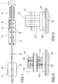
- the hot plastic profile 2 emerging from a profile nozzle 1 following an extruder is drawn through a calibrating device 3 before it passes through a cooling tank 4, in which calibrating diaphragms 5 arranged at a distance are provided to ensure the dimensional accuracy of the plastic profile 2 during cooling.
- the Kalibrierblenden 5 must therefore be designed so that the cooling-induced shrinkage of the plastic profile 2 is taken into account.
- the cooling liquid used for cooling the plastic profile 2 is usually water, wherein the plastic profile 2 is drawn through a cooling liquid bath 6 in the cooling tank 4.
- damping devices 9 are used as needed , which reduce the vibrations occurring at least to a permissible size.
- damping devices are therefore preferably provided in the region between the cooling tank 4 and the draw-off device 7, but also in the cooling tank 4, preferably in the outlet-side third.
- the structural design of the damping devices can be very different because it is only important to correspondingly reduce the vibrations of the plastic profile 2, in particular in the longitudinal direction.
- a damping device 9 is provided in the region of the cooling tank 4, then an embodiment of the damping device in the form of a calibration diaphragm is recommended so as not to jeopardize the dimensional accuracy of the plastic profile 2.
- the aperture shape of the Damping device 9 can of course be used outside the cooling tank. 2 and 3 show such damping devices, which consist of two immediately adjacent Kalibrierblenden 10 and 11, which are offset transversely to the plastic profile 2 against each other, as indicated in Fig. 2 by arrows.
- the Kalibrierblenden 10 and 11 are employed by opposite sides of the plastic profile 2, can be effectively suppressed by this Kalibrierblendencover 10 and 11 longitudinal vibrations of the plastic profile 2.
- at least one of the two calibration apertures 10, 11 can be resiliently acted upon by a spring 12 in the direction of the mutual displacement of the two calibration apertures 10 and 11.
- the damping device 9 according to FIG. 3 differs from that according to FIG. 2 only in that the two calibration diaphragms 10 and 11 receiving housing 13 is not rigidly connected to a carrier 14, but is supported relative to this carrier 14 by spring body 15 , so that the damping device 9 is part of the determined by the plastic profile 1 vibration system, with the result that the natural oscillations of the vibration system shift, which can lead to a sufficient reduction in the prevailing for the occurrence of marks on the plastic profile 1 vibration amplitudes.
- the damping device 9 according to FIG. 4 likewise uses a calibration diaphragm pair, but the calibration diaphragms 10, 11 are pivoted relative to each other about a longitudinal axis of the plastic profile 2.
- the plastic profile 2 is 10 positively clamped again between these Kalibrierblenden 10 and 11, which has the desired suppression of longitudinal vibrations of the plastic profile 2 result without having to fear the dimensional stability of the plastic profile 2 endangering deformation of the plastic profile 2.
- the damping device 9 consists of one of the calibration plates 5 provided in the cooling tank 4, to which the plastic profile 2 adjacent damping body 16 are attached.
- These DämptungsKörper 16 preferably consist of a relation to the Kalibrierblende 5 different material to achieve different friction conditions relative to the plastic profile 2, whereby the desired vibration damping is supported.
- the damping bodies 16 at least one can be pressed by a spring 12 against the plastic profile 2.
- Fig. 6 shows a damping device 9, which consists of two plastic profile 2 between them leading damping rollers 17 which are excited via the longitudinal vibrations of the plastic profile 2 to torsional vibrations. Due to the different natural frequency of the damping rollers 17 results in an effective damping of the wings of the plastic profile 2.
- the damping rollers 17 are provided for better vibration damping with a rubber elastic layer 18, via which they act on the plastic profile 2, with a braking force on the damping rollers 17 advantageous can affect the vibration damping.
Landscapes
- Engineering & Computer Science (AREA)
- Mechanical Engineering (AREA)
- Physics & Mathematics (AREA)
- Thermal Sciences (AREA)
- Extrusion Moulding Of Plastics Or The Like (AREA)
- Processing And Handling Of Plastics And Other Materials For Molding In General (AREA)
- Vibration Prevention Devices (AREA)
Claims (7)
- Dispositif de refroidissement et de calibrage d'un profilé en matière synthétique (2) extrudé, avec un réservoir de refroidissement (4) recevant le liquide de refroidissement, avec des écrans de calibrage (5), disposés à distance les uns des autres à l'intérieur du réservoir de refroidissement (4), pour le profilé en matière synthétique (2) tiré à travers un bain de liquide de refroidissement dans le réservoir de refroidissement (4), et avec un dispositif d'extraction (7), installé en aval du réservoir de refroidissement (4) en observant dans la direction d'extraction du profilé en matière synthétique (2), caractérisé en ce qu'entre l'écran de calibrage (5), côté arrivée du réservoir de refroidissement (4) et le dispositif d'extraction (7) est prévu au moins un dispositif d'amortissement (9), amortissant, au moins par tronçons, des vibrations longitudinales du profilé en matière synthétique (2), s'appliquant dans.la zone d'une périphérie de ce profilé en matière synthétique (2), dispositif d'amortissement composé de deux écrans de calibrage (10, 11) se suivant directement, décalés l'un par rapport à l'autre transversalement par rapport au profilé en matière synthétique (2), ou décalés angulairement autour d'un axe longitudinal du profilé en matière synthétique (2), de deux galets d'amortissement (17), guidant entre eux le profilé en matière synthétique (2), ou d'un écran de calibrage (5), sur lequel sont appliqués des corps d'amortissement (16) appliqués sur le profilé en matière synthétique (2).
- Dispositif selon la revendication 1, caractérisé en ce qu'au moins l'un des écrans de calibrage (10,11) du dispositif d'amortissement (9) est susceptible d'être sollicité élastiquement dans la direction de son décalage par rapport à l'autre écran de calibrage (10,11).
- Dispositif selon la revendication 1, caractérisé en ce que les galets d'amortissement (17) sont appliqués sur le profilé en matière synthétique (2) avec une couche de défilement (18) ayant l'élasticité du caoutchouc.
- Dispositif selon la revendication 3, caractérisé en ce que les galets d'amortissement (17) sont susceptibles d'être pressés élastiquement sur le profilé en matière synthétique (2).
- Dispositif selon la revendication 1, caractérisé en ce que les corps d'amortissement (16) sont formés, au moins dans la zone de l'appui sur le profilé en matière synthétique (2), d'un matériau différent de celui de l'écran de calibrage (5) afférent.
- Dispositif selon la revendication 1 ou 5, caractérisé en ce que les corps d'amortissement (16) sont susceptibles d'êtres pressés élastiquement sur le profilé en matière synthétique (2).
- Dispositif selon l'une des revendications 1 à 6, caractérisé en ce que le dispositif d'amortissement (9) est soutenu sur un support (14), par l'intermédiaire de corps élastiques (15).
Priority Applications (1)
| Application Number | Priority Date | Filing Date | Title |
|---|---|---|---|
| AT02450050T ATE322968T1 (de) | 2001-04-09 | 2002-03-08 | Vorrichtung zum kühlen und kalibrieren eines extrudierten kunststoffprofils |
Applications Claiming Priority (2)
| Application Number | Priority Date | Filing Date | Title |
|---|---|---|---|
| AT2001565 | 2001-04-09 | ||
| AT0056501A AT409736B (de) | 2001-04-09 | 2001-04-09 | Vorrichtung zum kühlen und kalibrieren eines extrudierten kunststoffprofils |
Publications (2)
| Publication Number | Publication Date |
|---|---|
| EP1249332A1 EP1249332A1 (fr) | 2002-10-16 |
| EP1249332B1 true EP1249332B1 (fr) | 2006-04-12 |
Family
ID=3676662
Family Applications (1)
| Application Number | Title | Priority Date | Filing Date |
|---|---|---|---|
| EP02450050A Expired - Lifetime EP1249332B1 (fr) | 2001-04-09 | 2002-03-08 | Dispositif de refroidissement et de calibrage de profilés en matière plastique extrudés |
Country Status (4)
| Country | Link |
|---|---|
| US (1) | US6840748B2 (fr) |
| EP (1) | EP1249332B1 (fr) |
| AT (2) | AT409736B (fr) |
| DE (1) | DE50206352D1 (fr) |
Families Citing this family (5)
| Publication number | Priority date | Publication date | Assignee | Title |
|---|---|---|---|---|
| US7878792B2 (en) | 2005-03-16 | 2011-02-01 | Greiner Tool. Tec Gmbh | Support arrangement for an extrusion tool and extrusion tool for moulding an object |
| DE102010061997A1 (de) * | 2010-11-25 | 2012-05-31 | Greiner Tool.Tec Gmbh | Vorrichtung und Verfahren zur gezielten Verformung eines extrudierten Kunststoffprofils |
| HRP20230084T1 (hr) | 2012-08-09 | 2023-03-17 | Ceraloc Innovation Ab | Jednoslojno raspršavanje prahastih površina |
| US8993049B2 (en) | 2012-08-09 | 2015-03-31 | Valinge Flooring Technology Ab | Single layer scattering of powder surfaces |
| AT523885B1 (de) * | 2020-05-25 | 2024-05-15 | Extrunet Gmbh | Elektronische Unterstützung zum Ablängen von Profilmustern mit genauer Zuordnung der Extrusions- und Prüfparameter |
Family Cites Families (7)
| Publication number | Priority date | Publication date | Assignee | Title |
|---|---|---|---|---|
| US2423260A (en) * | 1944-12-29 | 1947-07-01 | Extruded Plasties Inc | Extrusion of tubing |
| US2903743A (en) * | 1954-01-18 | 1959-09-15 | Lysobey John | Manufacture of flexible-walled tubing |
| DE1157378B (de) * | 1959-05-06 | 1963-11-14 | Frieseke & Hoepfner Gmbh | Extruder-Anlage zum Herstellen von Hohlprofilen aus thermoplastischem Material |
| DE1201038B (de) * | 1960-05-19 | 1965-09-16 | Kloeckner Werke Ag | Vakuum-Kalibriervorrichtung fuer Hohlprofile aus Kunststoff |
| DE1504364A1 (de) * | 1964-12-31 | 1969-04-10 | Rheinstahl Henschel Ag | Einrichtung zum Blasen von Folien in horizontaler Arbeitsweise |
| US3552259A (en) * | 1968-07-19 | 1971-01-05 | Commerican Solvents Corp | Process and apparatus for preparing detonating and deflagrating fuse and product |
| DE2359975C3 (de) * | 1973-12-01 | 1980-09-18 | Hoechst Ag, 6000 Frankfurt | Kühlvorrichtung für Schlauchfolien |
-
2001
- 2001-04-09 AT AT0056501A patent/AT409736B/de not_active IP Right Cessation
-
2002
- 2002-03-08 DE DE50206352T patent/DE50206352D1/de not_active Expired - Fee Related
- 2002-03-08 AT AT02450050T patent/ATE322968T1/de not_active IP Right Cessation
- 2002-03-08 EP EP02450050A patent/EP1249332B1/fr not_active Expired - Lifetime
- 2002-04-08 US US10/118,408 patent/US6840748B2/en not_active Expired - Fee Related
Also Published As
| Publication number | Publication date |
|---|---|
| EP1249332A1 (fr) | 2002-10-16 |
| DE50206352D1 (de) | 2006-05-24 |
| AT409736B (de) | 2002-10-25 |
| US20020146477A1 (en) | 2002-10-10 |
| US6840748B2 (en) | 2005-01-11 |
| ATA5652001A (de) | 2002-03-15 |
| ATE322968T1 (de) | 2006-04-15 |
Similar Documents
| Publication | Publication Date | Title |
|---|---|---|
| EP0038920B1 (fr) | Bandage pneumatique rempli de gaz | |
| EP2712702B1 (fr) | Dispositif de finition de bande, système de finition de bande et procédé de fabrication d'un dispositif de finition de bande | |
| WO1992000865A1 (fr) | Essuie-glace pour vehicules a moteur | |
| DE3143612A1 (de) | "spruehdose" | |
| DE2852108A1 (de) | Rohrbrunnenfilter | |
| DE19831540C5 (de) | Partielle Veränderung des Fließkanalquerschnitts eines geschlossenen Strömungskanalquerschnitts | |
| DE68911310T2 (de) | Bahnmittenführung. | |
| DE102018102289A1 (de) | Hydrofoil | |
| DE102013220746A1 (de) | Vorrichtung und Verfahren zum Kühlen von Kunststoffprofilen | |
| EP0475084A1 (fr) | Support radial en forme de manchon | |
| WO2006012920A1 (fr) | Membrane de filtrage et procede de realisation | |
| EP0121158B1 (fr) | Dispositif de refroidissement pour feuilles de tuyaux en matière plastique extrudées dans une tête à soufflage de feuilles | |
| DE102006042065B4 (de) | Verfahren und Vorrichtung zur Herstellung von bandförmigen Kunststoffvorformlingen | |
| AT409736B (de) | Vorrichtung zum kühlen und kalibrieren eines extrudierten kunststoffprofils | |
| EP3325298B1 (fr) | Boudin d'étanchéité extrudé comportant des ouvertures de ventilation | |
| EP1144200B1 (fr) | Manchon en materiau thermoformable et procede permettant de le produire | |
| EP2958731B1 (fr) | Dispositif et procédé de fabrication de tubes en matière plastique | |
| EP0711648A2 (fr) | Dispositif pour le tirage | |
| DE102015207741A1 (de) | Sprühdüse | |
| EP0485860A1 (fr) | Dispositif pour la fabrication d'un profilé | |
| WO2014127959A1 (fr) | Dispositif de fabrication de tuyaux en matière plastique | |
| EP0849066B1 (fr) | Dispositif de calibrage pour un profilé en matière plastique et procédé d'utiliser le dispositif | |
| EP0926034A2 (fr) | Dispositif de montage de réservoirs d'air sous pression à un châssis d'un véhicule | |
| EP1291152A1 (fr) | Manchon de calibrage avec refroidissement intensif | |
| DE2456795A1 (de) | Vorrichtung zum thermischen vorspannen von glasscheiben |
Legal Events
| Date | Code | Title | Description |
|---|---|---|---|
| PUAI | Public reference made under article 153(3) epc to a published international application that has entered the european phase |
Free format text: ORIGINAL CODE: 0009012 |
|
| AK | Designated contracting states |
Kind code of ref document: A1 Designated state(s): AT BE CH CY DE DK ES FI FR GB GR IE IT LI LU MC NL PT SE TR |
|
| AX | Request for extension of the european patent |
Free format text: AL;LT;LV;MK;RO;SI |
|
| 17P | Request for examination filed |
Effective date: 20021118 |
|
| AKX | Designation fees paid |
Designated state(s): AT BE CH CY DE DK ES FI FR GB GR IE IT LI LU MC NL PT SE TR |
|
| 17Q | First examination report despatched |
Effective date: 20030619 |
|
| GRAP | Despatch of communication of intention to grant a patent |
Free format text: ORIGINAL CODE: EPIDOSNIGR1 |
|
| GRAS | Grant fee paid |
Free format text: ORIGINAL CODE: EPIDOSNIGR3 |
|
| GRAA | (expected) grant |
Free format text: ORIGINAL CODE: 0009210 |
|
| AK | Designated contracting states |
Kind code of ref document: B1 Designated state(s): AT BE CH CY DE DK ES FI FR GB GR IE IT LI LU MC NL PT SE TR |
|
| PG25 | Lapsed in a contracting state [announced via postgrant information from national office to epo] |
Ref country code: IT Free format text: LAPSE BECAUSE OF FAILURE TO SUBMIT A TRANSLATION OF THE DESCRIPTION OR TO PAY THE FEE WITHIN THE PRESCRIBED TIME-LIMIT;WARNING: LAPSES OF ITALIAN PATENTS WITH EFFECTIVE DATE BEFORE 2007 MAY HAVE OCCURRED AT ANY TIME BEFORE 2007. THE CORRECT EFFECTIVE DATE MAY BE DIFFERENT FROM THE ONE RECORDED. Effective date: 20060412 Ref country code: NL Free format text: LAPSE BECAUSE OF FAILURE TO SUBMIT A TRANSLATION OF THE DESCRIPTION OR TO PAY THE FEE WITHIN THE PRESCRIBED TIME-LIMIT Effective date: 20060412 Ref country code: IE Free format text: LAPSE BECAUSE OF FAILURE TO SUBMIT A TRANSLATION OF THE DESCRIPTION OR TO PAY THE FEE WITHIN THE PRESCRIBED TIME-LIMIT Effective date: 20060412 Ref country code: FI Free format text: LAPSE BECAUSE OF FAILURE TO SUBMIT A TRANSLATION OF THE DESCRIPTION OR TO PAY THE FEE WITHIN THE PRESCRIBED TIME-LIMIT Effective date: 20060412 |
|
| REG | Reference to a national code |
Ref country code: GB Ref legal event code: FG4D Free format text: NOT ENGLISH |
|
| REG | Reference to a national code |
Ref country code: CH Ref legal event code: EP |
|
| REF | Corresponds to: |
Ref document number: 50206352 Country of ref document: DE Date of ref document: 20060524 Kind code of ref document: P |
|
| REG | Reference to a national code |
Ref country code: IE Ref legal event code: FG4D Free format text: LANGUAGE OF EP DOCUMENT: GERMAN |
|
| PG25 | Lapsed in a contracting state [announced via postgrant information from national office to epo] |
Ref country code: DK Free format text: LAPSE BECAUSE OF FAILURE TO SUBMIT A TRANSLATION OF THE DESCRIPTION OR TO PAY THE FEE WITHIN THE PRESCRIBED TIME-LIMIT Effective date: 20060712 Ref country code: SE Free format text: LAPSE BECAUSE OF FAILURE TO SUBMIT A TRANSLATION OF THE DESCRIPTION OR TO PAY THE FEE WITHIN THE PRESCRIBED TIME-LIMIT Effective date: 20060712 |
|
| PG25 | Lapsed in a contracting state [announced via postgrant information from national office to epo] |
Ref country code: ES Free format text: LAPSE BECAUSE OF FAILURE TO SUBMIT A TRANSLATION OF THE DESCRIPTION OR TO PAY THE FEE WITHIN THE PRESCRIBED TIME-LIMIT Effective date: 20060723 |
|
| GBT | Gb: translation of ep patent filed (gb section 77(6)(a)/1977) |
Effective date: 20060705 |
|
| PG25 | Lapsed in a contracting state [announced via postgrant information from national office to epo] |
Ref country code: PT Free format text: LAPSE BECAUSE OF FAILURE TO SUBMIT A TRANSLATION OF THE DESCRIPTION OR TO PAY THE FEE WITHIN THE PRESCRIBED TIME-LIMIT Effective date: 20060912 |
|
| NLV1 | Nl: lapsed or annulled due to failure to fulfill the requirements of art. 29p and 29m of the patents act | ||
| REG | Reference to a national code |
Ref country code: IE Ref legal event code: FD4D |
|
| ET | Fr: translation filed | ||
| PLBE | No opposition filed within time limit |
Free format text: ORIGINAL CODE: 0009261 |
|
| STAA | Information on the status of an ep patent application or granted ep patent |
Free format text: STATUS: NO OPPOSITION FILED WITHIN TIME LIMIT |
|
| 26N | No opposition filed |
Effective date: 20070115 |
|
| REG | Reference to a national code |
Ref country code: CH Ref legal event code: PL |
|
| PG25 | Lapsed in a contracting state [announced via postgrant information from national office to epo] |
Ref country code: MC Free format text: LAPSE BECAUSE OF NON-PAYMENT OF DUE FEES Effective date: 20070331 |
|
| PG25 | Lapsed in a contracting state [announced via postgrant information from national office to epo] |
Ref country code: CH Free format text: LAPSE BECAUSE OF NON-PAYMENT OF DUE FEES Effective date: 20070331 Ref country code: LI Free format text: LAPSE BECAUSE OF NON-PAYMENT OF DUE FEES Effective date: 20070331 |
|
| PG25 | Lapsed in a contracting state [announced via postgrant information from national office to epo] |
Ref country code: GR Free format text: LAPSE BECAUSE OF FAILURE TO SUBMIT A TRANSLATION OF THE DESCRIPTION OR TO PAY THE FEE WITHIN THE PRESCRIBED TIME-LIMIT Effective date: 20060713 |
|
| PGFP | Annual fee paid to national office [announced via postgrant information from national office to epo] |
Ref country code: GB Payment date: 20080327 Year of fee payment: 7 |
|
| PG25 | Lapsed in a contracting state [announced via postgrant information from national office to epo] |
Ref country code: AT Free format text: LAPSE BECAUSE OF NON-PAYMENT OF DUE FEES Effective date: 20070308 |
|
| PGFP | Annual fee paid to national office [announced via postgrant information from national office to epo] |
Ref country code: DE Payment date: 20080422 Year of fee payment: 7 |
|
| PGFP | Annual fee paid to national office [announced via postgrant information from national office to epo] |
Ref country code: BE Payment date: 20080416 Year of fee payment: 7 Ref country code: TR Payment date: 20080305 Year of fee payment: 7 Ref country code: IT Payment date: 20080328 Year of fee payment: 7 |
|
| PGFP | Annual fee paid to national office [announced via postgrant information from national office to epo] |
Ref country code: FR Payment date: 20080319 Year of fee payment: 7 |
|
| PG25 | Lapsed in a contracting state [announced via postgrant information from national office to epo] |
Ref country code: CY Free format text: LAPSE BECAUSE OF FAILURE TO SUBMIT A TRANSLATION OF THE DESCRIPTION OR TO PAY THE FEE WITHIN THE PRESCRIBED TIME-LIMIT Effective date: 20060412 Ref country code: LU Free format text: LAPSE BECAUSE OF NON-PAYMENT OF DUE FEES Effective date: 20070308 |
|
| BERE | Be: lapsed |
Owner name: *A + G EXTRUSION TECHNOLOGY G.M.B.H. Effective date: 20090331 |
|
| GBPC | Gb: european patent ceased through non-payment of renewal fee |
Effective date: 20090308 |
|
| REG | Reference to a national code |
Ref country code: FR Ref legal event code: ST Effective date: 20091130 |
|
| PG25 | Lapsed in a contracting state [announced via postgrant information from national office to epo] |
Ref country code: DE Free format text: LAPSE BECAUSE OF NON-PAYMENT OF DUE FEES Effective date: 20091001 |
|
| PG25 | Lapsed in a contracting state [announced via postgrant information from national office to epo] |
Ref country code: BE Free format text: LAPSE BECAUSE OF NON-PAYMENT OF DUE FEES Effective date: 20090331 |
|
| PG25 | Lapsed in a contracting state [announced via postgrant information from national office to epo] |
Ref country code: FR Free format text: LAPSE BECAUSE OF NON-PAYMENT OF DUE FEES Effective date: 20091123 Ref country code: GB Free format text: LAPSE BECAUSE OF NON-PAYMENT OF DUE FEES Effective date: 20090308 |
|
| PG25 | Lapsed in a contracting state [announced via postgrant information from national office to epo] |
Ref country code: IT Free format text: LAPSE BECAUSE OF NON-PAYMENT OF DUE FEES Effective date: 20090308 |
|
| PG25 | Lapsed in a contracting state [announced via postgrant information from national office to epo] |
Ref country code: TR Free format text: LAPSE BECAUSE OF NON-PAYMENT OF DUE FEES Effective date: 20090308 |