EP1249410A2 - Vorrichtung mit einer Plattform, einem Stützkörper und Luftpolstererzeugungsmitteln - Google Patents
Vorrichtung mit einer Plattform, einem Stützkörper und Luftpolstererzeugungsmitteln Download PDFInfo
- Publication number
- EP1249410A2 EP1249410A2 EP02007700A EP02007700A EP1249410A2 EP 1249410 A2 EP1249410 A2 EP 1249410A2 EP 02007700 A EP02007700 A EP 02007700A EP 02007700 A EP02007700 A EP 02007700A EP 1249410 A2 EP1249410 A2 EP 1249410A2
- Authority
- EP
- European Patent Office
- Prior art keywords
- platform
- support body
- air cushion
- air
- cylindrical
- Prior art date
- Legal status (The legal status is an assumption and is not a legal conclusion. Google has not performed a legal analysis and makes no representation as to the accuracy of the status listed.)
- Granted
Links
Images

Classifications
-
- B—PERFORMING OPERATIONS; TRANSPORTING
- B65—CONVEYING; PACKING; STORING; HANDLING THIN OR FILAMENTARY MATERIAL
- B65G—TRANSPORT OR STORAGE DEVICES, e.g. CONVEYORS FOR LOADING OR TIPPING, SHOP CONVEYOR SYSTEMS OR PNEUMATIC TUBE CONVEYORS
- B65G54/00—Non-mechanical conveyors not otherwise provided for
- B65G54/02—Non-mechanical conveyors not otherwise provided for electrostatic, electric, or magnetic
-
- B—PERFORMING OPERATIONS; TRANSPORTING
- B65—CONVEYING; PACKING; STORING; HANDLING THIN OR FILAMENTARY MATERIAL
- B65G—TRANSPORT OR STORAGE DEVICES, e.g. CONVEYORS FOR LOADING OR TIPPING, SHOP CONVEYOR SYSTEMS OR PNEUMATIC TUBE CONVEYORS
- B65G51/00—Conveying articles through pipes or tubes by fluid flow or pressure; Conveying articles over a flat surface, e.g. the base of a trough, by jets located in the surface
- B65G51/02—Directly conveying the articles, e.g. slips, sheets, stockings, containers or workpieces, by flowing gases
- B65G51/03—Directly conveying the articles, e.g. slips, sheets, stockings, containers or workpieces, by flowing gases over a flat surface or in troughs
Definitions
- the invention relates to a device with a platform, at least one support body and air cushion generating means to create an air cushion between the platform and the support body, either the Platform or the support body with an air-slide bearing translational is movable.
- the device has an air slide bearing platform that can be moved in translation.
- Air-bearing platforms lie on one suitable means between the platform and a support body generated air cushion. This will make the platform supported without direct contact with the support body. Due to the low coefficient of friction between air and Platform has very little stiction between the platform and the air cushion. There is also only slight sliding friction when moving the platform between the platform and the air cushion. The platform can therefore be set in motion with little effort and keep moving.
- the platform which is also rectangular, is covered by one between the horizontal surface of the support body and air cushion generated by the platform.
- the platform is designed such that it supports the body grips laterally with vertical guide elements.
- the support body with its surface facing the platform is completely flat. Otherwise, the Variation of the gap width between platform and support body the air cushion in its properties, for example the pressure in the air cushion, vary. Variations of Properties of the air cushion, in particular the pressure in the Air cushions lead to uneven movement of the platform. Especially in applications where the platform along the support body to precisely controlled points must be moved, it is necessary to move the Platform to be carried out evenly so that it can be easily regulated is. Because within the necessary for such systems tight tolerances completely flat, rectangular surfaces can only be produced with great effort the support body made only a short length. From The device known in practice has, for example Length of 1.2 m.
- the invention is technical Underlying problem, the device mentioned above train that on the one hand inexpensive support body great length can be used and that above all a reliable, trouble-free and precise movement the platform or the support body is possible.
- the invention teaches to solve this technical problem a device of the type mentioned, which thereby is characterized in that the support body is cylindrical is and that the support body in a partially cylindrical Recessing the platform under training engages in a circular arc-shaped gap.
- That the support body is cylindrical means in Within the scope of the invention in particular that the support body in Cross-section is circular cylindrical.
- Cylindrical part Recess of the platform means that the Wall of the recess in the form of a circular arc in cross section is.
- the recess in the platform expediently comprises at least a third of the circumference of the cylindrical Support body.
- the cylindrical support body preferably with at least one Third of its circumference in the partially cylindrical recess intervenes. That between the platform and the cylindrical support body a gap formed in the shape of a circular arc means in particular the condition already generated air cushion.
- the Device according to the invention preferably an air slide bearing translationally movable platform and at least on the other hand, a fixed support body. This Embodiment is also explained further below.
- Cylindrical support bodies are also available in long lengths to establish exact tolerances with regard to their cylindricity. This makes it possible to have an air cushion between to generate the support body and platform that along the length of the support body does not vary. This in particular because of the gap between the platform and the support body always remains the same. Because the air cushion can be generated consistently and thus the coefficient of friction between the air cushion and the platform remains the same, is the movement of the platform along the Support body easily adjustable. This especially with regard a constant speed, but also in terms of the exact positioning of the platform on a target Place along the support body. Furthermore, the Platform always at a constant distance from the support body held.
- Air cushion generation means are suitable means which Introduce air between the platform and the support body in such a way that an air cushion is formed there.
- Air cushion generating means that generate air jets that either from the support body against that facing the support body Surface of the platform or opposite are. Such air jets develop their supporting function among other things because they are against the platform or bounce the support body.
- the air cushion is at one such an embodiment of the invention on the one hand by a Variety of in particular aligned parallel to each other Air jets and secondly through the bounced off Air of air jets formed, which - pressurized - The gap between the platform and the support body crowded.
- the air cushion generation means in the arcuate gap between Support body and platform are arranged. It also lies in the context of the invention that in the longitudinal direction cylindrical support body a plurality of air cushion generating means are arranged one behind the other. After a lot preferred embodiment, within the scope of the invention is of particular importance, at least part of it the in a partially cylindrical recess of the platform air cushion generating means arranged one behind the other in Regarding the circumference of the respective cylindrical support body staggered. This results in a particularly reliable and exact guidance or Movement of the platform.
- the platform must have a shape that matches the air cushion facing a sufficiently large and accordingly designed area in order for given fluid and given pressure the platform to the support body without contact hold.
- the platform can be used by anyone desired application have the necessary form and is regarding their shape is not rectangular, plane Forms limited.
- the platform preferably instructs its side facing away from the support body is a flat one, in particular rectangular area. So that the platform be used as a movable table on which to move Elements can be attached.
- the platform can also be part of a component to be moved, for example a robot, robot part or a door to be moved.
- the invention is based on the knowledge that a particularly good guidance of the platform during its movement along the support body is reached when the platform engages at least partially around the support body.
- the platform therefore encompasses the cylindrical one Support body at least partially.
- the gap between the Platform and the support body then has a circular arc Cross section on.
- the air cushion generating means or that generated therewith Air cushions provide effective cushioning, especially against mechanical influences on the platform.
- a stable guidance of the platform becomes special with one preferred embodiment of the device according to the invention reached, in which two parallel cylindrical Support bodies are provided which are in two parallel part-cylindrical Recesses a platform under training one each with a circular arc-shaped gap intervention.
- the support body support by means of between The platform created air cushions for them and the platform in the manner of a rail, so that it is reliably prevented that the platform is moving around the longitudinal axis of a support body rotates.
- the Support body along its longitudinal axis by one on one Base plate attached support element supported.
- Support element can be any element that the Support body supports along its longitudinal axis and sagging of the support body prevented.
- Supporting element an elongated, rectangular web, which the Support body supported on the side facing away from the platform.
- the support element is in a preferred embodiment firmly connected to the support body to thereby support of the supporting body that is as stable as possible to reach.
- Each element / element group is the base plate understand on which the support body is carried and with which he can be firmly connected by means of the support element should. This can be the case, for example, when using robots Be the floor of a manufacturing facility along which the Robot should be moved.
- the base plate can become the element of the milling machine along which the workpiece or tool is guided shall be.
- the air cushion generating means on the cylindrical support body attached. It is within the scope of the invention that then between one on the cylindrical support body attached air cushion generating means and the platform or the partially cylindrical recess of the platform in Cross-section of an arcuate air gap is provided.
- the air cushion generating means are preferably spherical hung on the platform and that's what Air cushion generation appropriately via ball bearings hung on the platform. In this way it is achieved that the air cushion generation means as it were can align. In addition, fluctuations in parallelism of the cylindrical support body effective be balanced.
- Air gap in cross-section refers to thereby on the condition of the device in which a Air cushion is generated.
- Air gap has between an air cushion generating means and the platform or between one Air cushion generating means and the support body Air gap a gap thickness of 3 to 40 microns, preferably from 3 to 30 ⁇ m, preferably from 5 to 30 ⁇ m.
- the gap thickness of the air cushion is expediently variable furnishable. It is within the scope of the invention that the Platform facing surface of a on a support body attached air cushion generating means of the surface of the partially cylindrical recess of the platform is adapted.
- the surface an air cushion generating means attached to the platform the cylindrical surface of the support body is adjusted. It is then expedient at the edges or on the edges of the air cushion generating means between the air cushion generating means and the cylindrical surface of the support body an air gap same or constant gap thickness.
- the device is particularly simple if on the peripheral surface of the support body as an air cushion generating means Air jet generating means arranged are.
- the platform can also be used with air cushion generation means be equipped, but this leads that air supply lines are provided on the platform are that have to be moved with the platform.
- Stationary air supply lines can, however, be provided when the air cushion generating means on the Provided peripheral surface of the stationary support body become.
- These air jet generators can be nozzles which are introduced into the peripheral surface of the support body become. These nozzles then generate air jets Air that is under pressure by a provided in the support body Line is led to these nozzles.
- the air jet generating means formed by airpads.
- airpads are to be understood as elements or devices that can be mounted on the support body and some or generate multiple jets of air. These can be elements be with nozzles to which air is supplied via a feed line becomes. But it can also be devices that from the Pick up surrounding fluid, compress it and as an air jet submit.
- the airpads can be designed so that they are dependent on the air jets Create the position of the platform along the support body. A suitable jet can then be used to control an air jet always be generated at the point where the platform located while the air jets in others Areas of the support body are not generated. This The advantage is particularly evident when there are several airpads are provided on the support body, which are independent of generate air jets at each other. The Airpads in whose Area the platform is not located not be operated.
- a Drive provided for translatory movement of the platform.
- the drive can for example, be a stepper motor.
- the Stepper motor can be integrated into the platform and the Rack in which the stepper motor engages, parallel to the Support body can be arranged, for example on the Baseplate.
- the drive can be operated by a appropriately designed piston-cylinder unit is formed whose piston is connected to the platform and whose lifting movement takes place along the support body.
- other types of drives like spindle drive, belt drive, Chain drive or other linear drives possible.
- the drive is preferably a linear motor.
- the Linear motor enables a contactless drive of the Platform in the form that that connected to the platform Drive means not with the base plate or other elements that are fixed relative to the support body must be connected or must come into contact. This will Frictional losses within the drive means at the Movement of the platform minimized.
- the linear motor can be designed such that the Coil-bearing primary part (stand) in the platform is integrated and the secondary part (reaction part) is stationary, for example on the base plate, on the support body or another, fixed relative to the support body Element is arranged. In this case it is only to provide the platform with electrical connections. To build the platform, however, simply too hold, the linear motor can alternatively be constructed in this way be that the primary part is fixed relative to Support body is arranged and the platform the secondary part wearing.
- two platforms according to an embodiment of the invention Can be moved translationally in two orthogonal directions are. This is the case, for example, with an embodiment of the Invention achieved in the orthogonal in two planes mutually supporting bodies are provided and first Support bodies are arranged on a platform, which over an air cushion on second, orthogonal to the first standing support bodies is supported.
- the device shown in Fig. 1 has a platform 1, cylindrical guide body 2, 3 and a base plate 4 on.
- the cylindrical guide bodies 2, 3 are web-like Support elements 5, 6 connected to the base plate 4 and are supported by the support elements 5, 6 along their supported entire length.
- the support bodies 2, 3 have their peripheral surfaces as air cushion generation means 7, 8 Airpads on.
- the platform 1 carries the primary part 9 Linear motor.
- the secondary part 10 of the linear motor is on the base plate 4 arranged.
- the platform 1 has on its support bodies 2, 3 facing away On a flat, rectangular surface 11, attached to the elements to be moved, not shown can be.
- the side facing the support bodies 2, 3 the platform 1 has two partially cylindrical recesses 19 in which recesses 19 the cylindrical support body 2, 3 to form circular arcs in cross section Intervene columns 12, 13.
- Bubble generating means 7, 8 are in the arcuate columns 12, 13 arranged between support body 2, 3 and platform 1.
- Ribbon cable not shown, leads electrical Lines to the primary part arranged in the platform 1 9 of the linear motor.
- the ribbon cable is designed that - without obstructing the movement of platform 1 - over the entire length of the support body 2, 3 electrical lines and the air supply to the platform 1 can lead.
- the support bodies 2, 3 are with respect to their longitudinal axis arranged parallel to each other and tower over the platform 1 such that it moves along the support body 2, 3 can be.
- the arranged on the support bodies 2, 3 Air cushion generation means 7, 8 is not shown above Lines of compressed air supplied.
- the air cushion generating means 7, 8 have nozzles 14, 15 from which the compressed air emerges in the form of air jets.
- the nozzles 14, 15 of the air cushion generating means 7, 8 and the further air cushion generating means, not shown are aligned in such a way that the air jets from the Support bodies 2, 3 are directed against the platform 1.
- the nozzles 14, 15 are aligned such that the air jets generated by them do not run parallel.
- the nozzles 14, 15 exit Air jets formed an air cushion that the platform 1 supports.
- the non-parallel alignment of the air jets leads to an exact guidance of the platform 1, because horizontal or vertical deviations in the along the support body 2, 3 aligned movement of the platform 1 by the one directed against the direction of deviation Air jets generated impulse and the partial Reduction of columns 12, 13 in these areas increased pressure in the air cushion can be corrected.
- the platform 1 is driven by the linear motor. A driving force or a braking force is generated.
- the driving or braking force can be regulated so that platform 1 is predefined Make moves along the support body 2, 3 and can be stopped exactly at these points.
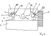
- FIG. 2 is a second embodiment of the invention Device shown, which differs from the first differs by the type of drive. To avoid of repetitions are only the ones below distinguishing components described. Same components are identified by the same reference numerals.
- the platform 1 driven by a linear motor. With this Linear motor, the platform 1 carries the primary part 16, the engages around a cylindrical secondary part 17.
- the cylindrical secondary part 17 is between the support bodies 2, 3 arranged and held at the ends.
- a driving or braking force is in the primary part 16 provided coil with electrical current via lines supplied, which are guided in an elongated ribbon cable 18 become.
- the platform 1 is powered by the air cushion generation means 7, 8 generated air cushion stored and by the driving force of the cylindrical linear motor moved along the support body 2, 3.
- the cylindrical support body are in terms of Tolerances of their cylindricity are produced so precisely, that column 12, 13 between the platform 1 and the support bodies 2, 3 along the entire length of the support body remain the same. Because due the constant gap the air cushion in this The gap also remains the same, the platform can be even can be moved by the linear motor without the Platform in its movement through a varying air cushion is accelerated or slowed down.
- the Gap thickness (i.e. distance between the surface of the air cushion generating agent 7, 8 and the surface of the support body 2, 3) is in the micrometer range and preferably Is 5 to 25 ⁇ m.
- the air cushion generating means 7, 8 on the support bodies 2, 3 attached This also preferably results a not shown in the form of a circular arc in cross section Air gap between platform 1 and air cushion generating means 7, 8, which also expediently the aforementioned Gap thickness (distance of the surface of the platform 1 from the surface of the air cushion generating means 7, 8) having.
Landscapes
- Physics & Mathematics (AREA)
- Engineering & Computer Science (AREA)
- Fluid Mechanics (AREA)
- Mechanical Engineering (AREA)
- Magnetic Bearings And Hydrostatic Bearings (AREA)
- Invalid Beds And Related Equipment (AREA)
- Fluid-Damping Devices (AREA)
- Mattresses And Other Support Structures For Chairs And Beds (AREA)
Abstract
Description
- Fig. 1
- eine erste Ausführungsform der erfindungsgemäßen Vorrichtung in einer perspektivischen Ansicht und
- Fig. 2
- eine zweite Ausführungsform der erfindungsgemäßen Vorrichtung in einer Draufsicht.
Claims (10)
- Vorrichtung mit einer Plattform (1) und mindestens einem Stützkörper (2, 3) und Luftpolstererzeugungsmitteln (7, 8) zur Erzeugung eines Luftpolsters zwischen der Plattform (1) und dem Stützkörper (2, 3), wobei entweder die Plattform (1) oder der Stützkörper (2, 3) luftgleitgelagert translatorisch bewegbar ist, dadurch gekennzeichnet,dass der Stützkörper (2, 3) zylindrisch ausgebildet ist und dass der Stützkörper (2, 3) in eine teilzylindrische Ausnehmung (19) der Plattform (1) unter Ausbildung eines im Querschnitt kreisbogenförmigen Spaltes (12, 13) eingreift.
- Vorrichtung nach Anspruch 1, dadurch gekennzeichnet, dass die Luftpolstererzeugungsmittel (7, 8) in dem kreisbogenförmigen Spalt (12, 13) zwischen Stützkörper (2, 3) und Plattform (1) angeordnet sind.
- Vorrichtung nach einem der Ansprüche 1 oder 2, dadurch gekennzeichnet, dass in Längsrichtung des zylindrischen Stützkörpers (2, 3) eine Mehrzahl von Luftpolstererzeugungsmitteln (7, 8) hintereinander angeordnet sind.
- Vorrichtung nach Anspruch 3, dadurch gekennzeichnet, dass zumindest ein Teil der Luftpolstererzeugungsmittel (7, 8) in Bezug auf den Umfang des zylindrischen Stützkörpers (2, 3) versetzt zueinander angeordnet sind.
- Vorrichtung nach einem der Ansprüche 1 bis 4, dadurch gekennzeichnet, dass die Luftpolstererzeugungsmittel (7, 8) an der Plattform (1) befestigt sind.
- Vorrichtung nach einem der Ansprüche 1 bis 5, dadurch gekennzeichnet, dass die Luftpolstererzeugungsmittel (7, 8) an dem zylindrischen Stützkörper (2, 3) befestigt sind.
- Vorrichtung nach einem der Ansprüche 1 bis 6, dadurch gekennzeichnet, dass der zwischen einem Luftpolstererzeugungsmittel (7, 8) und der Plattform (1) oder der zwischen einem Luftpolstererzeugungsmittel (7, 8) und dem Stützkörper (2, 3) ausgebildete Luftspalt (20) eine Spaltdicke von 3 bis 30 µm, vorzugsweise von 5 bis 30 µm aufweist.
- Vorrichtung nach einem der Ansprüche 1 bis 7, dadurch gekennzeichnet, dass zwei zueinander parallele zylindrische Stützkörper (2, 3) vorgesehen sind, die in zwei parallele teilzylindrische Ausnehmungen (19) einer Plattform (1) unter Ausbildung jeweils eines im Querschnitt kreisbogenförmigen Spaltes (12, 13) eingreifen.
- Vorrichtung nach einem der Ansprüche 1 bis 8, dadurch gekennzeichnet, dass als Luftpolstererzeugungsmittel (7, 8) Luftstrahlerzeugungsmittel vorgesehen sind.
- Vorrichtung nach Anspruch 9, dadurch gekennzeichnet, dass die Luftstrahlerzeugungsmittel Airpads sind.
Applications Claiming Priority (2)
| Application Number | Priority Date | Filing Date | Title |
|---|---|---|---|
| DE10117632 | 2001-04-09 | ||
| DE10117632A DE10117632A1 (de) | 2001-04-09 | 2001-04-09 | Vorrichtung mit einer luftgleitgelagerten, translatorisch bewegbaren Plattform |
Publications (3)
| Publication Number | Publication Date |
|---|---|
| EP1249410A2 true EP1249410A2 (de) | 2002-10-16 |
| EP1249410A3 EP1249410A3 (de) | 2003-04-09 |
| EP1249410B1 EP1249410B1 (de) | 2005-08-03 |
Family
ID=7680927
Family Applications (1)
| Application Number | Title | Priority Date | Filing Date |
|---|---|---|---|
| EP02007700A Expired - Lifetime EP1249410B1 (de) | 2001-04-09 | 2002-04-05 | Vorrichtung mit einer Plattform, einem Stützkörper und Luftpolstererzeugungsmitteln |
Country Status (3)
| Country | Link |
|---|---|
| EP (1) | EP1249410B1 (de) |
| AT (1) | ATE301096T1 (de) |
| DE (2) | DE10117632A1 (de) |
Cited By (2)
| Publication number | Priority date | Publication date | Assignee | Title |
|---|---|---|---|---|
| US20100206229A1 (en) * | 2008-05-30 | 2010-08-19 | Alta Devices, Inc. | Vapor deposition reactor system |
| EP3681830A4 (de) * | 2017-09-13 | 2021-06-23 | Laitram, LLC | Einschienentablettförderer mit passiven führungsschienen |
Family Cites Families (7)
| Publication number | Priority date | Publication date | Assignee | Title |
|---|---|---|---|---|
| CA1002565A (en) * | 1973-11-15 | 1976-12-28 | Herbert E. Gladish | Vehicular transportation system |
| DE3344267A1 (de) * | 1982-10-30 | 1984-06-20 | Hitachi Kiden Kogyo K.K., Amagasaki | Foerderer, insbesondere mit luftkissen und linearmotor |
| US4627362A (en) * | 1983-06-28 | 1986-12-09 | Kabushiki Kaisha Myotoku | Air sliding device for work pallets or the like |
| CA1167797A (en) * | 1983-06-30 | 1984-05-22 | Herbert E. Gladish | Air conveyor components |
| US5668421A (en) * | 1995-04-06 | 1997-09-16 | E. B. Eddy Forest Products Ltd. | Pressurized air-gap guided active linear motor suspension system |
| US5566620A (en) * | 1995-11-16 | 1996-10-22 | Siewert; Bradley D. | Levitated rail system |
| US5909710A (en) * | 1997-08-15 | 1999-06-08 | Cummins; Richard D. | Air-levitated train |
-
2001
- 2001-04-09 DE DE10117632A patent/DE10117632A1/de not_active Withdrawn
-
2002
- 2002-04-05 EP EP02007700A patent/EP1249410B1/de not_active Expired - Lifetime
- 2002-04-05 AT AT02007700T patent/ATE301096T1/de not_active IP Right Cessation
- 2002-04-05 DE DE50203806T patent/DE50203806D1/de not_active Expired - Lifetime
Cited By (3)
| Publication number | Priority date | Publication date | Assignee | Title |
|---|---|---|---|---|
| US20100206229A1 (en) * | 2008-05-30 | 2010-08-19 | Alta Devices, Inc. | Vapor deposition reactor system |
| EP3681830A4 (de) * | 2017-09-13 | 2021-06-23 | Laitram, LLC | Einschienentablettförderer mit passiven führungsschienen |
| AU2018331269B2 (en) * | 2017-09-13 | 2024-01-04 | Laitram, L.L.C. | Monorail tray conveyor with passive guide rails |
Also Published As
| Publication number | Publication date |
|---|---|
| ATE301096T1 (de) | 2005-08-15 |
| EP1249410B1 (de) | 2005-08-03 |
| DE50203806D1 (de) | 2005-09-08 |
| DE10117632A1 (de) | 2002-10-17 |
| EP1249410A3 (de) | 2003-04-09 |
Similar Documents
| Publication | Publication Date | Title |
|---|---|---|
| DE69701818T2 (de) | Unterstützungseinheit und Mechanismus für einen Tisch mit mehreren Freiheitsgraden | |
| DE3909292C2 (de) | Längs- und Quer-Tischführungs- und -drehmechanismus | |
| DE3100141C2 (de) | ||
| DE19650360A1 (de) | Antriebseinheit für eine Maschine | |
| DE102006056516A1 (de) | Lineareinheit | |
| DE102012103554B4 (de) | Koordinatenmessgerät | |
| EP0812652A1 (de) | Vorrichtung zur Bearbeitung und/oder Montage von Werkstücken | |
| DE10106601B4 (de) | Führungseinrichtung für eine fluidbetätigte Spannzange | |
| DE2756183C2 (de) | Präzisions-Vorschubtisch | |
| WO1999008832A1 (de) | Vorrichtung zum bewegen und positionieren eines gegenstandes in einer ebene | |
| DE102019101071B3 (de) | Hybridkinematik mit sechs Freiheitsgraden und Verfahren | |
| DE4111889C2 (de) | Handhabungsvorrichtung | |
| DE102013226826A1 (de) | Linearmotoranordnung und Werkzeugmaschine mit einer Linearmotoranordnung | |
| EP3342547B1 (de) | Positioniereinheit | |
| EP1249410B1 (de) | Vorrichtung mit einer Plattform, einem Stützkörper und Luftpolstererzeugungsmitteln | |
| EP2241771A2 (de) | Linearachse | |
| DE102007037886B4 (de) | Feldgeführter planarer Präzisionsantrieb mit einem luftgelagerten Läufer | |
| EP0105246B1 (de) | Antriebs- und Führungsvorrichtung mit einem Hubzylinder und einem Übertragungselement | |
| EP1611412B2 (de) | Manipulator für eine prüfvorrichtung für zerstörungsfreie materialprüfung | |
| DE102004025061B4 (de) | Werkzeugantrieb, insbesondere zum automatischen Entgraten, Kantenbrechen oder Verputzen von Werkstücken | |
| DE102008020252A1 (de) | CNC-Werkzeugmaschine mit einem Gleitelement, welches mit einer hohen Geschwindigkeit bewegbar ist | |
| EP1632308A1 (de) | Linearbewegungsführung mit zwei parallelen Führungsschienen und Verfahren zu deren Herstellung | |
| EP1585634A1 (de) | Werkzeugführungsvorrichtung | |
| EP3524386A1 (de) | Vorrichtung zum abstützen eines zu bearbeitenden werkstücks | |
| WO2002014012A1 (de) | Kreuztisch zur bereitstellung von bewegungen in einem zweidimensionalen koordinatensystem |
Legal Events
| Date | Code | Title | Description |
|---|---|---|---|
| PUAI | Public reference made under article 153(3) epc to a published international application that has entered the european phase |
Free format text: ORIGINAL CODE: 0009012 |
|
| AK | Designated contracting states |
Kind code of ref document: A2 Designated state(s): AT BE CH CY DE DK ES FI FR GB GR IE IT LI LU MC NL PT SE TR |
|
| AX | Request for extension of the european patent |
Free format text: AL;LT;LV;MK;RO;SI |
|
| PUAL | Search report despatched |
Free format text: ORIGINAL CODE: 0009013 |
|
| AK | Designated contracting states |
Kind code of ref document: A3 Designated state(s): AT BE CH CY DE DK ES FI FR GB GR IE IT LI LU MC NL PT SE TR |
|
| AX | Request for extension of the european patent |
Extension state: AL LT LV MK RO SI |
|
| RIC1 | Information provided on ipc code assigned before grant |
Ipc: 7B 65G 54/02 B Ipc: 7B 65G 51/03 A Ipc: 7B 60V 3/04 B Ipc: 7B 23Q 1/38 B |
|
| 17P | Request for examination filed |
Effective date: 20031002 |
|
| AKX | Designation fees paid |
Designated state(s): AT BE CH CY DE DK ES FI FR GB GR IE IT LI LU MC NL PT SE TR |
|
| 17Q | First examination report despatched |
Effective date: 20040116 |
|
| GRAP | Despatch of communication of intention to grant a patent |
Free format text: ORIGINAL CODE: EPIDOSNIGR1 |
|
| GRAS | Grant fee paid |
Free format text: ORIGINAL CODE: EPIDOSNIGR3 |
|
| GRAA | (expected) grant |
Free format text: ORIGINAL CODE: 0009210 |
|
| AK | Designated contracting states |
Kind code of ref document: B1 Designated state(s): AT BE CH CY DE DK ES FI FR GB GR IE IT LI LU MC NL PT SE TR |
|
| PG25 | Lapsed in a contracting state [announced via postgrant information from national office to epo] |
Ref country code: NL Free format text: LAPSE BECAUSE OF FAILURE TO SUBMIT A TRANSLATION OF THE DESCRIPTION OR TO PAY THE FEE WITHIN THE PRESCRIBED TIME-LIMIT Effective date: 20050803 Ref country code: IE Free format text: LAPSE BECAUSE OF FAILURE TO SUBMIT A TRANSLATION OF THE DESCRIPTION OR TO PAY THE FEE WITHIN THE PRESCRIBED TIME-LIMIT Effective date: 20050803 Ref country code: IT Free format text: LAPSE BECAUSE OF FAILURE TO SUBMIT A TRANSLATION OF THE DESCRIPTION OR TO PAY THE FEE WITHIN THE PRESCRIBED TIME-LIMIT;WARNING: LAPSES OF ITALIAN PATENTS WITH EFFECTIVE DATE BEFORE 2007 MAY HAVE OCCURRED AT ANY TIME BEFORE 2007. THE CORRECT EFFECTIVE DATE MAY BE DIFFERENT FROM THE ONE RECORDED. Effective date: 20050803 Ref country code: GB Free format text: LAPSE BECAUSE OF FAILURE TO SUBMIT A TRANSLATION OF THE DESCRIPTION OR TO PAY THE FEE WITHIN THE PRESCRIBED TIME-LIMIT Effective date: 20050803 Ref country code: FI Free format text: LAPSE BECAUSE OF FAILURE TO SUBMIT A TRANSLATION OF THE DESCRIPTION OR TO PAY THE FEE WITHIN THE PRESCRIBED TIME-LIMIT Effective date: 20050803 Ref country code: TR Free format text: LAPSE BECAUSE OF FAILURE TO SUBMIT A TRANSLATION OF THE DESCRIPTION OR TO PAY THE FEE WITHIN THE PRESCRIBED TIME-LIMIT Effective date: 20050803 |
|
| REG | Reference to a national code |
Ref country code: GB Ref legal event code: FG4D Free format text: NOT ENGLISH |
|
| REG | Reference to a national code |
Ref country code: CH Ref legal event code: EP |
|
| REG | Reference to a national code |
Ref country code: IE Ref legal event code: FG4D Free format text: LANGUAGE OF EP DOCUMENT: GERMAN |
|
| REF | Corresponds to: |
Ref document number: 50203806 Country of ref document: DE Date of ref document: 20050908 Kind code of ref document: P |
|
| PG25 | Lapsed in a contracting state [announced via postgrant information from national office to epo] |
Ref country code: SE Free format text: LAPSE BECAUSE OF FAILURE TO SUBMIT A TRANSLATION OF THE DESCRIPTION OR TO PAY THE FEE WITHIN THE PRESCRIBED TIME-LIMIT Effective date: 20051103 Ref country code: GR Free format text: LAPSE BECAUSE OF FAILURE TO SUBMIT A TRANSLATION OF THE DESCRIPTION OR TO PAY THE FEE WITHIN THE PRESCRIBED TIME-LIMIT Effective date: 20051103 Ref country code: DK Free format text: LAPSE BECAUSE OF FAILURE TO SUBMIT A TRANSLATION OF THE DESCRIPTION OR TO PAY THE FEE WITHIN THE PRESCRIBED TIME-LIMIT Effective date: 20051103 |
|
| PG25 | Lapsed in a contracting state [announced via postgrant information from national office to epo] |
Ref country code: ES Free format text: LAPSE BECAUSE OF FAILURE TO SUBMIT A TRANSLATION OF THE DESCRIPTION OR TO PAY THE FEE WITHIN THE PRESCRIBED TIME-LIMIT Effective date: 20051114 |
|
| PG25 | Lapsed in a contracting state [announced via postgrant information from national office to epo] |
Ref country code: PT Free format text: LAPSE BECAUSE OF FAILURE TO SUBMIT A TRANSLATION OF THE DESCRIPTION OR TO PAY THE FEE WITHIN THE PRESCRIBED TIME-LIMIT Effective date: 20060103 |
|
| NLV1 | Nl: lapsed or annulled due to failure to fulfill the requirements of art. 29p and 29m of the patents act | ||
| GBV | Gb: ep patent (uk) treated as always having been void in accordance with gb section 77(7)/1977 [no translation filed] |
Effective date: 20050803 |
|
| REG | Reference to a national code |
Ref country code: IE Ref legal event code: FD4D |
|
| PG25 | Lapsed in a contracting state [announced via postgrant information from national office to epo] |
Ref country code: AT Free format text: LAPSE BECAUSE OF NON-PAYMENT OF DUE FEES Effective date: 20060405 |
|
| PG25 | Lapsed in a contracting state [announced via postgrant information from national office to epo] |
Ref country code: CH Free format text: LAPSE BECAUSE OF NON-PAYMENT OF DUE FEES Effective date: 20060430 Ref country code: MC Free format text: LAPSE BECAUSE OF NON-PAYMENT OF DUE FEES Effective date: 20060430 Ref country code: LI Free format text: LAPSE BECAUSE OF NON-PAYMENT OF DUE FEES Effective date: 20060430 Ref country code: BE Free format text: LAPSE BECAUSE OF NON-PAYMENT OF DUE FEES Effective date: 20060430 |
|
| PLBE | No opposition filed within time limit |
Free format text: ORIGINAL CODE: 0009261 |
|
| STAA | Information on the status of an ep patent application or granted ep patent |
Free format text: STATUS: NO OPPOSITION FILED WITHIN TIME LIMIT |
|
| 26N | No opposition filed |
Effective date: 20060504 |
|
| EN | Fr: translation not filed | ||
| PG25 | Lapsed in a contracting state [announced via postgrant information from national office to epo] |
Ref country code: FR Free format text: LAPSE BECAUSE OF FAILURE TO SUBMIT A TRANSLATION OF THE DESCRIPTION OR TO PAY THE FEE WITHIN THE PRESCRIBED TIME-LIMIT Effective date: 20060929 |
|
| REG | Reference to a national code |
Ref country code: CH Ref legal event code: PL |
|
| BERE | Be: lapsed |
Owner name: AWU PRAZISIONSWELLEN G.M.B.H. & CO.KG Effective date: 20060430 |
|
| PG25 | Lapsed in a contracting state [announced via postgrant information from national office to epo] |
Ref country code: LU Free format text: LAPSE BECAUSE OF NON-PAYMENT OF DUE FEES Effective date: 20060405 |
|
| PG25 | Lapsed in a contracting state [announced via postgrant information from national office to epo] |
Ref country code: CY Free format text: LAPSE BECAUSE OF FAILURE TO SUBMIT A TRANSLATION OF THE DESCRIPTION OR TO PAY THE FEE WITHIN THE PRESCRIBED TIME-LIMIT Effective date: 20050803 Ref country code: FR Free format text: LAPSE BECAUSE OF FAILURE TO SUBMIT A TRANSLATION OF THE DESCRIPTION OR TO PAY THE FEE WITHIN THE PRESCRIBED TIME-LIMIT Effective date: 20050803 |
|
| PGFP | Annual fee paid to national office [announced via postgrant information from national office to epo] |
Ref country code: DE Payment date: 20100408 Year of fee payment: 9 |
|
| PG25 | Lapsed in a contracting state [announced via postgrant information from national office to epo] |
Ref country code: DE Free format text: LAPSE BECAUSE OF NON-PAYMENT OF DUE FEES Effective date: 20111101 |
|
| REG | Reference to a national code |
Ref country code: DE Ref legal event code: R119 Ref document number: 50203806 Country of ref document: DE Effective date: 20111101 |