EP1249918B1 - Rotor pour une machine électrique du type à aimant permanent - Google Patents
Rotor pour une machine électrique du type à aimant permanent Download PDFInfo
- Publication number
- EP1249918B1 EP1249918B1 EP02007834A EP02007834A EP1249918B1 EP 1249918 B1 EP1249918 B1 EP 1249918B1 EP 02007834 A EP02007834 A EP 02007834A EP 02007834 A EP02007834 A EP 02007834A EP 1249918 B1 EP1249918 B1 EP 1249918B1
- Authority
- EP
- European Patent Office
- Prior art keywords
- rotor
- electrical machine
- rotating electrical
- openings
- set forth
- Prior art date
- Legal status (The legal status is an assumption and is not a legal conclusion. Google has not performed a legal analysis and makes no representation as to the accuracy of the status listed.)
- Expired - Lifetime
Links
- 230000003014 reinforcing effect Effects 0.000 claims description 5
- 239000002826 coolant Substances 0.000 claims description 4
- 238000001816 cooling Methods 0.000 description 24
- 239000003921 oil Substances 0.000 description 11
- 230000001965 increasing effect Effects 0.000 description 7
- 230000004907 flux Effects 0.000 description 4
- 230000003247 decreasing effect Effects 0.000 description 3
- 238000005549 size reduction Methods 0.000 description 3
- 230000000694 effects Effects 0.000 description 2
- 230000002708 enhancing effect Effects 0.000 description 2
- 238000005259 measurement Methods 0.000 description 2
- 229910000831 Steel Inorganic materials 0.000 description 1
- QJVKUMXDEUEQLH-UHFFFAOYSA-N [B].[Fe].[Nd] Chemical compound [B].[Fe].[Nd] QJVKUMXDEUEQLH-UHFFFAOYSA-N 0.000 description 1
- 230000001133 acceleration Effects 0.000 description 1
- 230000015572 biosynthetic process Effects 0.000 description 1
- 238000005266 casting Methods 0.000 description 1
- 238000010273 cold forging Methods 0.000 description 1
- 230000001419 dependent effect Effects 0.000 description 1
- 238000011161 development Methods 0.000 description 1
- 230000018109 developmental process Effects 0.000 description 1
- 238000004049 embossing Methods 0.000 description 1
- 238000005242 forging Methods 0.000 description 1
- 230000006698 induction Effects 0.000 description 1
- 230000002452 interceptive effect Effects 0.000 description 1
- 239000007788 liquid Substances 0.000 description 1
- 239000010687 lubricating oil Substances 0.000 description 1
- 239000000696 magnetic material Substances 0.000 description 1
- 239000000463 material Substances 0.000 description 1
- 238000012986 modification Methods 0.000 description 1
- 230000004048 modification Effects 0.000 description 1
- 229910001172 neodymium magnet Inorganic materials 0.000 description 1
- 125000006850 spacer group Chemical group 0.000 description 1
- 239000010959 steel Substances 0.000 description 1
- 238000005406 washing Methods 0.000 description 1
- 238000004804 winding Methods 0.000 description 1
Images



Classifications
-
- H—ELECTRICITY
- H02—GENERATION; CONVERSION OR DISTRIBUTION OF ELECTRIC POWER
- H02K—DYNAMO-ELECTRIC MACHINES
- H02K1/00—Details of the magnetic circuit
- H02K1/06—Details of the magnetic circuit characterised by the shape, form or construction
- H02K1/22—Rotating parts of the magnetic circuit
- H02K1/32—Rotating parts of the magnetic circuit with channels or ducts for flow of cooling medium
-
- H—ELECTRICITY
- H02—GENERATION; CONVERSION OR DISTRIBUTION OF ELECTRIC POWER
- H02K—DYNAMO-ELECTRIC MACHINES
- H02K1/00—Details of the magnetic circuit
- H02K1/06—Details of the magnetic circuit characterised by the shape, form or construction
- H02K1/22—Rotating parts of the magnetic circuit
- H02K1/27—Rotor cores with permanent magnets
- H02K1/2786—Outer rotors
- H02K1/2787—Outer rotors the magnetisation axis of the magnets being perpendicular to the rotor axis
- H02K1/2789—Outer rotors the magnetisation axis of the magnets being perpendicular to the rotor axis the rotor consisting of two or more circumferentially positioned magnets
- H02K1/2791—Surface mounted magnets; Inset magnets
-
- H—ELECTRICITY
- H02—GENERATION; CONVERSION OR DISTRIBUTION OF ELECTRIC POWER
- H02K—DYNAMO-ELECTRIC MACHINES
- H02K9/00—Arrangements for cooling or ventilating
- H02K9/02—Arrangements for cooling or ventilating by ambient air flowing through the machine
- H02K9/04—Arrangements for cooling or ventilating by ambient air flowing through the machine having means for generating a flow of cooling medium
- H02K9/06—Arrangements for cooling or ventilating by ambient air flowing through the machine having means for generating a flow of cooling medium with fans or impellers driven by the machine shaft
-
- H—ELECTRICITY
- H02—GENERATION; CONVERSION OR DISTRIBUTION OF ELECTRIC POWER
- H02K—DYNAMO-ELECTRIC MACHINES
- H02K7/00—Arrangements for handling mechanical energy structurally associated with dynamo-electric machines, e.g. structural association with mechanical driving motors or auxiliary dynamo-electric machines
- H02K7/18—Structural association of electric generators with mechanical driving motors, e.g. with turbines
- H02K7/1807—Rotary generators
- H02K7/1815—Rotary generators structurally associated with reciprocating piston engines
Definitions
- This invention relates to a rotor for a permanent magnet type rotary electrical machine having permanent magnets adapted to cooperate with the coils formed on armatures of a stator.
- a rotary machine In both motors and generators such as those used in vehicles such as motorcycles, a rotary machine has been known in which permanent magnets fixed to a rotor are rotated around a stator. In such a machine not only does the rotor rotate at high speed, but also the permanent magnets are subjected to repeated attractive and repulsive forces between the magnets and the coils of the stator. This can and does cause generation of vibration and noise. Because the quality and strength of permanent magnets gas improved and permanent magnets with very large magnetic flux density are now used, the attractive and repulsive forces are increased further.
- the rotor has not only a large weight, but also a large moment of inertia.
- a generator When such a generator is used in a vehicle, it causes not only an increase in vehicle weight, but also a drop in the acceleration and deceleration of the engine. Because electric power consumption has increased especially in the newer model vehicles the load of the generator is increased. The resulting generator tends to be larger in size and to have a larger capacity. This still further amplifies the weight and moment of inertia.
- Document EP-A-1 094 145 which is a post-published document, discloses an electrical machine, namely a driving unit for a drum type washing machine.
- the rotor comprises an embossing which may be regarded as reinforcing ribs.
- Document EP-A-0 887 908 shows a rotor of an electrical machine comprising ribs extending from a center to a circumferential part of the rotor, wherein at the end of the ribs at the circumferential part, the ribs are bent in the rotational direction and in the opposite direction.
- Document EP-A-1 018 795 discloses a rotor as set out in the preamble of claim 1.
- this document shows the structure of a rotor for an outer rotor type brushless motor.
- the rotor comprises a cylindrical portion to which permanent magnets are attached, a center portion which can be attached to a rotable shaft.
- the center portion also connects the hub portion (i.e., the part of the center portion to which the shaft is to be connected) with the cylindrical portion.
- enhancing ribs are provided in the interconnecting portion.
- the machines of this type can generate substantial heat and this heat must be dissipated. This can be done by using fans or other auxiliary cooling structures. This brings with it further problems of weight and inertia, not to mention added cost.
- a rotating electrical machine such as a generator is indicated generally by the reference numeral 21.
- a generator Although described as a generator, it will be readily apparent to those skilled in the art, the invention can be used equally with an electric motor.
- the generator 21 is incorporated in an engine, shown only partially, for a motorcycle or the like, and is disposed and driven at one end of the engine crankshaft 22 (FIG. 1). In such an arrangement, the generator 21 is enclosed in a generator housing section 23 formed between a crankcase 24 of the engine and a generator cover 25 mounted to the crankcase 24.
- crankshaft 22 protrudes from the crankcase 24 into the generator housing section 23.
- a stator 26 is fixedly supported on the crankcase 24 in surrounding relation to the protruding portion of the crankshaft 22.
- the stator 26 is formed of radial magnetic pole teeth 27 of a stator core, and coils 28 wound thereon.
- the number of magnetic pole teeth 27 is a multiple of three, and for example, 9, 12, 15 and 18 poles are provided.
- the winding directions of the coils 28 of each phase are arranged to be normal or reverse corresponding to the magnetic poles of permanent magnets 29 of a rotor, indicated generally by the reference numeral 31 and to be described later, to which these coils 28 face so that voltages induced by the coils 28 of the same phase have the same polarity.
- the rotor 31 is comprised of a hub section 32 fitted fixedly on the crankshaft 22, a cylindrical section 33 facing close to the outside circumference of the magnetic pole teeth of the stator 26, and a plate-like spoke section 34 for connecting the hub section 32 and the cylindrical section 26.
- the hub section 32, spoke section 34 and cylindrical section 33 of the rotor 31 are integrally formed from a material like steel by cold forging or hot forging.
- the hub section 32 is nonrotatably key-fitted on a tapered portion formed at one end of the crankshaft 22, and fixed axially to the crankshaft 22 by a bolt 35.
- the permanent magnets 29 are bonded on the inside circumferential surface of the cylindrical section 33 and a small clearance is provided between the permanent magnets 29 and the outside circumference of the stator 26.
- the permanent magnets 29 are magnetized such that they have polarities changing circumferentially at regular intervals, that is, into twelve or sixteen poles.
- the permanent magnets 29 used here are preferably neodymium-iron-boron magnets with high flux density.
- the magnets 29 have a very large flux density, so that their thickness can be decreased, which is suited for size reduction and weight saving of the generator 21.
- a spacer 36 made of non-magnetic material.
- a number of radial ribs 37 are formed on the inside surface of the spoke section 34, that is, on a surface on the stator 26 side. These ribs 37 extend from the hub section 32 to the cylindrical section 33. The ends 37a of the ribs 37 near the cylindrical section 33 are each bent in an arc in the rotational direction R (Figs. 3 and 4) of the rotor 31.
- the spoke section 34 is also formed with a number of windows 38 that extend therethrough in the direction of a rotation axis B of the rotor in a position close to but not interfering with the ribs 37 and particularly their curved portions 37a.
- Groove-like slant faces 39 are formed on the surface of the spoke section 34 opposite to that on which the ribs 37 are provide. These groove-like slant faces 39 are formed at one side of the windows in the circumferential direction, configured such that they begin at the opening edges (leading side) of the windows 38 and their depths are gradually shallower in the rotational direction (R) of the rotor 26.
- the generator 21 is air-cooled or liquid-cooled.
- the whole generator In the case of liquid cooling, the whole generator is immersed in cooling oil. That is, cooling oil, for example engine lubricating oil, is circulated in the generator housing section 23.
- the cooling oil is preferably cooled down by an oil cooler or the like (not shown).
- this embodiment has twelve ribs 37 and twelve windows 38, so that the number of magnetic poles of the magnets 29 fixed to the cylindrical section 33 is preferably twelve.
- the numbers of ribs 37 and windows 38 are not limited to that, but they may be changed depending on the number of magnetic poles of the permanent magnets or the like.
- rotation of the crankshaft 22 causes the rotor 31 to rotate in the direction (R).
- magnetic field produced by the permanent magnets 29 fixed to the cylindrical section 33 is rotated, which changes the number of magnetic fluxes passing through coils of the stator 26, resulting in induction of voltages in the coils.
- the permanent magnets 29 are subjected alternately to attractive and repulsive forces every time they move past different magnetic pole teeth while facing thereto. These forces form a vibration source to the cylindrical section 33, which could cause vibration of the entire rotor 31.
- the formation and shape of the windows 38 causes cooling air or cooling oil in the generator housing 23 to be circulated inside the rotor 31, accelerating the cooling of the stator 26. Therefore, size reduction and capacity increase of the generator 21 is effected.
- the cooling air or the cooling oil which has entered the rotor 31 strikes against the ribs 37 is dispersed into surrounding areas.
- the ribs 37 have the function of enhancing cooling effects.
- cooling air (oil) flows efficiently into the rotor 31 along the slant faces 39 as guides.
- improvement of cooling performance is further effected.
- the ribs 37 are bent in the rotational direction (R) of the rotor at the ends on the cylindrical side, so that cooling air (oil) which has entered at the windows 38 is introduced radially inwardly of the rotor along the bent sections 37A as guides. Therefore, cooling air (oil) is possibly introduced successfully also to the rotor 31 near the hub section32, enabling improvement of the cooling property as well.
- FIG. 6 illustrates the stator coil temperature, in comparison, of the case where ribs (37), windows (38) and slant faces (39) are provided according to this embodiment (cooling type, dash lines) and the case where no ribs, windows nor slant faces are provided (standard type, dash lines).
- measurement of the stator coil temperature is made on the generator 21 under the same load.
- FIG. 7 illustrates a rotor of another embodiment.
- a rotor indicated generally at 31a is arranged such that a hub section 32a is separated from the united body of a cylindrical section 33a and a spoke section 34a, and both members are coupled with rivets 51.
- the rotor 31a is divided into two members (32a and the united body of 33a and 34a) without decreasing the effect of this invention, thereby facilitating forming of each member.
- like parts as shown in FIG. 2 are designated by like reference numerals and further description is believed to be unnecessary to permit those skilled in the art to utilize this embodiment.
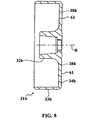
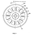
- a rotor constructed in accordance with an example not forming part of the present invention is indicated generally at 31b.
- the rotor 31b is similar to that of FIGS. 1-5 in that a hub section 32b, a cylindrical section 33b and a spoke section 34b are molded integrally.
- the spoke section 34b is formed with approximately fan-shaped twelve windows 38b at regular intervals in the circumferential direction.
- straight sections 61 extending approximately in the radial direction. These straight sections 61 act as stiffening ribs. On one edges of the straight sections 61 on the side in the leading side of the rotational direction of the rotor are formed, by chamfering, slant faces 62 in the longitudinal direction of the straight sections 61. That is, the slant faces 62 face to the outside of the rotor 31b.
- cooling air or cooling oil flows smoothly and efficiently into the rotor 31b along the slant faces 62 as guides.
- dash lines show the flow of the cooling air (oil). Therefore, cooling properties of the rotor 31b and the stator (not shown) enclosed in the rotor 31b is improved.
- ribs of the rotor extend approximately radially. Therefore, rigidity can be increased without need of increasing the weight and moment of inertia of the rotor, so that vibration of the stator is restricted as well as generation of noise. Also openings formed between the ribs permit coolant to flow from one side of the rotor to the other for cooling.
- rotors for rotating electrical machines configured to increase the stiffness without increasing the weight and to promote the flow of coolant across the rotor. This is achieved by utilizing stiffening ribs and flow openings in an intermediate portion of the rotor that interconnects the cylindrical portion that carries the permanent magnets and the hub section.
Landscapes
- Engineering & Computer Science (AREA)
- Power Engineering (AREA)
- Iron Core Of Rotating Electric Machines (AREA)
- Permanent Field Magnets Of Synchronous Machinery (AREA)
- Motor Or Generator Cooling System (AREA)
- Permanent Magnet Type Synchronous Machine (AREA)
Claims (8)
- Rotor pour machine électrique tournante, se composant d'une partie cylindrique (33) supportant une pluralité d'aimants permanents espacés, d'une partie de moyeu (32) adaptée pour être fixée sur un arbre rotatif (22), d'une partie d'interconnexion (34) destinée à connecter entre elles ladite partie cylindrique et ladite partie de moyeu, et d'une pluralité de nervures de renfort (37) formées dans ladite partie d'interconnexion ;
caractérisé en ce que,
les nervures de renfort (37) comprennent des sections courbes (37A) courbées dans la direction de la rotation du rotor (31) ;
des ouvertures (38) sont aménagées dans la partie d'interconnexion (34) entre les nervures de renfort (37), afin de permettre l'écoulement d'un fluide de refroidissement au travers de celles-ci ; et
les ouvertures (38) sont aménagées à proximité des sections courbes (37A) de telle sorte que les sections courbes (37A) sont courbées autour des ouvertures afin de permettre l'introduction le fluide de refroidissement à l'intérieur du rotor dans le sens radial le long des sections courbes qui servent de guides. - Rotor pour machine électrique tournante selon la revendication 1, caractérisé en ce que la partie cylindrique (33) et la partie d'interconnexion (34) sont incorporées l'une à l'autre.
- Rotor pour machine électrique tournante selon la revendication 2, caractérisé en ce que la partie de moyeu (32) est incorporée aux parties restantes.
- Rotor pour machine électrique tournante selon la revendication 1, caractérisé en ce que les nervures (37) s'étendent vers l'extérieur dans le sens axial à partir d'une partie en forme de disque qui s'étend vers l'intérieur dans le sens radial à partir de la partie cylindrique sur un côté de celle-ci.
- Rotor pour machine électrique tournante selon la revendication 1, caractérisé en ce que les ouvertures sont circulaires et qu'un côté de la section intermédiaire situé à proximité de chaque ouverture est dépouillé vers l'ouverture.
- Rotor pour machine électrique tournante selon la revendication 1, caractérisé en ce que les ouvertures (38) comprennent des faces obliques (39) sur un côté des ouvertures (38).
- Rotor pour machine électrique tournante selon la revendication 6, caractérisé en ce que les faces obliques (39) sont aménagées à la surface de la partie d'interconnexion (34) en opposition à la surface sur laquelle sont aménagées les nervures de renfort (37).
- Rotor pour machine électrique tournante selon la revendication 7, caractérisé en ce que les faces obliques (39) sont aménagées sur le côté des ouvertures (38) en opposition aux sections courbes (37A).
Applications Claiming Priority (4)
| Application Number | Priority Date | Filing Date | Title |
|---|---|---|---|
| JP2001110208 | 2001-04-09 | ||
| JP2001110208A JP2002315245A (ja) | 2001-04-09 | 2001-04-09 | 永久磁石式発電機のロータ |
| US10/063,148 US20020145348A1 (en) | 2001-04-09 | 2002-03-26 | Rotor for a permanent magnet type generator |
| US63148 | 2002-03-26 |
Publications (2)
| Publication Number | Publication Date |
|---|---|
| EP1249918A1 EP1249918A1 (fr) | 2002-10-16 |
| EP1249918B1 true EP1249918B1 (fr) | 2005-10-26 |
Family
ID=26613305
Family Applications (1)
| Application Number | Title | Priority Date | Filing Date |
|---|---|---|---|
| EP02007834A Expired - Lifetime EP1249918B1 (fr) | 2001-04-09 | 2002-04-08 | Rotor pour une machine électrique du type à aimant permanent |
Country Status (4)
| Country | Link |
|---|---|
| EP (1) | EP1249918B1 (fr) |
| CN (1) | CN1380734A (fr) |
| DE (1) | DE60206829T2 (fr) |
| TW (1) | TWI260122B (fr) |
Families Citing this family (8)
| Publication number | Priority date | Publication date | Assignee | Title |
|---|---|---|---|---|
| JP2007135379A (ja) | 2005-11-14 | 2007-05-31 | Mitsubishi Electric Corp | 磁石発電機 |
| JP2008154391A (ja) * | 2006-12-19 | 2008-07-03 | Mitsubishi Electric Corp | 磁石発電機 |
| EP2523320A1 (fr) * | 2011-05-13 | 2012-11-14 | Siemens Aktiengesellschaft | Entraînement de combinaison pour un mouvement de rotation et de levée et moteur linéaire ayant une inertie réduite |
| DE102014101039A1 (de) * | 2014-01-29 | 2015-07-30 | Dr. Ing. H.C. F. Porsche Aktiengesellschaft | Elektrische Maschine |
| EP2993762A1 (fr) * | 2014-09-02 | 2016-03-09 | ABB Technology AG | Ensemble de rotor de machine électrique |
| DE102018116988A1 (de) * | 2018-07-13 | 2020-01-16 | Nidec Corporation | Elektromotor mit einstückigem Innenläufer-Rotorkern |
| CN112072814A (zh) * | 2020-09-18 | 2020-12-11 | 珠海格力节能环保制冷技术研究中心有限公司 | 转子组件、电机、压缩机及制冷装置 |
| US12609585B2 (en) | 2023-11-13 | 2026-04-21 | Abb Schweiz Ag | Outer rotor electric motor assemblies for industrial applications |
Family Cites Families (11)
| Publication number | Priority date | Publication date | Assignee | Title |
|---|---|---|---|---|
| FR528970A (fr) * | 1917-01-31 | 1921-11-22 | Villiers Engineering Co Ltd | Perfectionnements apportés aux magnétos-volants pour moteurs à combustion interne |
| DD120981A1 (fr) * | 1975-07-25 | 1976-07-05 | ||
| US4510409A (en) * | 1982-09-28 | 1985-04-09 | Nippondenso Co., Ltd. | Heat insulation and heat dissipation construction for flat electric rotary machine |
| GB9510997D0 (en) * | 1995-05-31 | 1995-07-26 | Turbo Genset The Company Ltd | Rotary electrical machines |
| DE19547745A1 (de) * | 1995-12-20 | 1997-06-26 | Bosch Siemens Hausgeraete | Antriebsvorrichtung für eine von vorn beschickbare Waschmaschine |
| JP3017953B2 (ja) * | 1996-07-24 | 2000-03-13 | 株式会社東芝 | 電動機の回転子及びその製造方法 |
| EP0854558A3 (fr) * | 1997-01-21 | 2000-07-12 | Isuzu Ceramics Research Institute Co., Ltd. | Structure de rotor pour générateurs et procédé de fabrication du rotor |
| US5994804A (en) * | 1998-12-07 | 1999-11-30 | Sundstrand Corporation | Air cooled dynamoelectric machine |
| JP2000184644A (ja) * | 1998-12-17 | 2000-06-30 | Matsushita Electric Ind Co Ltd | アウタロータモータとそのアウタロータモータを備えた機器 |
| EP1018795B1 (fr) * | 1999-01-08 | 2008-03-05 | Lg Electronics Inc. | Structure d'un rotor pour moteur sans balais à rotor extérieur |
| AU782017B2 (en) * | 1999-10-18 | 2005-06-30 | Lg Electronics Inc. | A driving unit for a drum type washing machine |
-
2002
- 2002-04-08 DE DE60206829T patent/DE60206829T2/de not_active Expired - Fee Related
- 2002-04-08 EP EP02007834A patent/EP1249918B1/fr not_active Expired - Lifetime
- 2002-04-09 TW TW091107075A patent/TWI260122B/zh not_active IP Right Cessation
- 2002-04-09 CN CN02105509.2A patent/CN1380734A/zh active Pending
Also Published As
| Publication number | Publication date |
|---|---|
| DE60206829T2 (de) | 2006-05-18 |
| DE60206829D1 (de) | 2005-12-01 |
| CN1380734A (zh) | 2002-11-20 |
| TWI260122B (en) | 2006-08-11 |
| EP1249918A1 (fr) | 2002-10-16 |
Similar Documents
| Publication | Publication Date | Title |
|---|---|---|
| US20020145348A1 (en) | Rotor for a permanent magnet type generator | |
| JP4148460B2 (ja) | 自動車用の改良された回転電気機器 | |
| EP1102385B1 (fr) | Machine électrique tournante pour véhicule | |
| JP4887128B2 (ja) | 回転電機 | |
| JP4389918B2 (ja) | 回転電機及び交流発電機 | |
| US20040036367A1 (en) | Rotor cooling apparatus | |
| JP2917815B2 (ja) | 回転電機 | |
| US20050179336A1 (en) | Axial gap electric rotary machine | |
| JP4912258B2 (ja) | 回転電機 | |
| CN100405710C (zh) | 旋转电机 | |
| US20040212259A1 (en) | Wheel motor | |
| EP1253701A2 (fr) | Moteur | |
| US5917263A (en) | Switched reluctance motor | |
| JP2000152537A (ja) | ロ―タを高速用に特別適合させた電気装置 | |
| JP2009148057A (ja) | 車両用交流発電機 | |
| EP1130740B1 (fr) | Véhicule électrique hybride avec une machine électrodynamique à aimant permanent | |
| JPWO2003098781A6 (ja) | 回転電機 | |
| JP3569148B2 (ja) | 回転電機及びそれを用いた電動車両 | |
| EP1249918B1 (fr) | Rotor pour une machine électrique du type à aimant permanent | |
| JP3294497B2 (ja) | 交流発電機 | |
| JP2002252947A (ja) | 回転電機とそれを用いた電動車両 | |
| US20230275478A1 (en) | Rotor and Electrical Machine | |
| JP2011234555A (ja) | 車両用交流発電機の配設構造 | |
| JP6230649B2 (ja) | 車両用回転電機 | |
| JP4556408B2 (ja) | クローポール形回転機 |
Legal Events
| Date | Code | Title | Description |
|---|---|---|---|
| PUAI | Public reference made under article 153(3) epc to a published international application that has entered the european phase |
Free format text: ORIGINAL CODE: 0009012 |
|
| AK | Designated contracting states |
Kind code of ref document: A1 Designated state(s): AT BE CH CY DE DK ES FI FR GB GR IE IT LI LU MC NL PT SE TR |
|
| AX | Request for extension of the european patent |
Free format text: AL;LT;LV;MK;RO;SI |
|
| 17P | Request for examination filed |
Effective date: 20021202 |
|
| 17Q | First examination report despatched |
Effective date: 20030423 |
|
| AKX | Designation fees paid |
Designated state(s): DE FR IT |
|
| GRAP | Despatch of communication of intention to grant a patent |
Free format text: ORIGINAL CODE: EPIDOSNIGR1 |
|
| GRAS | Grant fee paid |
Free format text: ORIGINAL CODE: EPIDOSNIGR3 |
|
| GRAA | (expected) grant |
Free format text: ORIGINAL CODE: 0009210 |
|
| AK | Designated contracting states |
Kind code of ref document: B1 Designated state(s): DE FR IT |
|
| PG25 | Lapsed in a contracting state [announced via postgrant information from national office to epo] |
Ref country code: IT Free format text: LAPSE BECAUSE OF FAILURE TO SUBMIT A TRANSLATION OF THE DESCRIPTION OR TO PAY THE FEE WITHIN THE PRESCRIBED TIME-LIMIT;WARNING: LAPSES OF ITALIAN PATENTS WITH EFFECTIVE DATE BEFORE 2007 MAY HAVE OCCURRED AT ANY TIME BEFORE 2007. THE CORRECT EFFECTIVE DATE MAY BE DIFFERENT FROM THE ONE RECORDED. Effective date: 20051026 |
|
| REF | Corresponds to: |
Ref document number: 60206829 Country of ref document: DE Date of ref document: 20051201 Kind code of ref document: P |
|
| PLBE | No opposition filed within time limit |
Free format text: ORIGINAL CODE: 0009261 |
|
| STAA | Information on the status of an ep patent application or granted ep patent |
Free format text: STATUS: NO OPPOSITION FILED WITHIN TIME LIMIT |
|
| 26N | No opposition filed |
Effective date: 20060727 |
|
| EN | Fr: translation not filed | ||
| PG25 | Lapsed in a contracting state [announced via postgrant information from national office to epo] |
Ref country code: FR Free format text: LAPSE BECAUSE OF FAILURE TO SUBMIT A TRANSLATION OF THE DESCRIPTION OR TO PAY THE FEE WITHIN THE PRESCRIBED TIME-LIMIT Effective date: 20061215 |
|
| PG25 | Lapsed in a contracting state [announced via postgrant information from national office to epo] |
Ref country code: FR Free format text: LAPSE BECAUSE OF FAILURE TO SUBMIT A TRANSLATION OF THE DESCRIPTION OR TO PAY THE FEE WITHIN THE PRESCRIBED TIME-LIMIT Effective date: 20051026 |
|
| PGFP | Annual fee paid to national office [announced via postgrant information from national office to epo] |
Ref country code: DE Payment date: 20090402 Year of fee payment: 8 |
|
| PG25 | Lapsed in a contracting state [announced via postgrant information from national office to epo] |
Ref country code: DE Free format text: LAPSE BECAUSE OF NON-PAYMENT OF DUE FEES Effective date: 20101103 |