EP1249975A2 - Procédé de controle de la qualité d'une communication utilisant l'état de la transmission des paquets temps réel et l'état de congestion du chemin de transmission - Google Patents
Procédé de controle de la qualité d'une communication utilisant l'état de la transmission des paquets temps réel et l'état de congestion du chemin de transmission Download PDFInfo
- Publication number
- EP1249975A2 EP1249975A2 EP20020006552 EP02006552A EP1249975A2 EP 1249975 A2 EP1249975 A2 EP 1249975A2 EP 20020006552 EP20020006552 EP 20020006552 EP 02006552 A EP02006552 A EP 02006552A EP 1249975 A2 EP1249975 A2 EP 1249975A2
- Authority
- EP
- European Patent Office
- Prior art keywords
- terminal device
- media packets
- transmission
- transmitting terminal
- packet
- Prior art date
- Legal status (The legal status is an assumption and is not a legal conclusion. Google has not performed a legal analysis and makes no representation as to the accuracy of the status listed.)
- Withdrawn
Links
Images


Classifications
-
- H—ELECTRICITY
- H04—ELECTRIC COMMUNICATION TECHNIQUE
- H04L—TRANSMISSION OF DIGITAL INFORMATION, e.g. TELEGRAPHIC COMMUNICATION
- H04L12/00—Data switching networks
-
- H—ELECTRICITY
- H04—ELECTRIC COMMUNICATION TECHNIQUE
- H04L—TRANSMISSION OF DIGITAL INFORMATION, e.g. TELEGRAPHIC COMMUNICATION
- H04L65/00—Network arrangements, protocols or services for supporting real-time applications in data packet communication
- H04L65/80—Responding to QoS
-
- H—ELECTRICITY
- H04—ELECTRIC COMMUNICATION TECHNIQUE
- H04L—TRANSMISSION OF DIGITAL INFORMATION, e.g. TELEGRAPHIC COMMUNICATION
- H04L47/00—Traffic control in data switching networks
- H04L47/10—Flow control; Congestion control
-
- H—ELECTRICITY
- H04—ELECTRIC COMMUNICATION TECHNIQUE
- H04L—TRANSMISSION OF DIGITAL INFORMATION, e.g. TELEGRAPHIC COMMUNICATION
- H04L47/00—Traffic control in data switching networks
- H04L47/10—Flow control; Congestion control
- H04L47/11—Identifying congestion
- H04L47/115—Identifying congestion using a dedicated packet
-
- H—ELECTRICITY
- H04—ELECTRIC COMMUNICATION TECHNIQUE
- H04L—TRANSMISSION OF DIGITAL INFORMATION, e.g. TELEGRAPHIC COMMUNICATION
- H04L47/00—Traffic control in data switching networks
- H04L47/10—Flow control; Congestion control
- H04L47/24—Traffic characterised by specific attributes, e.g. priority or QoS
- H04L47/2416—Real-time traffic
-
- H—ELECTRICITY
- H04—ELECTRIC COMMUNICATION TECHNIQUE
- H04L—TRANSMISSION OF DIGITAL INFORMATION, e.g. TELEGRAPHIC COMMUNICATION
- H04L47/00—Traffic control in data switching networks
- H04L47/10—Flow control; Congestion control
- H04L47/26—Flow control; Congestion control using explicit feedback to the source, e.g. choke packets
- H04L47/263—Rate modification at the source after receiving feedback
-
- H—ELECTRICITY
- H04—ELECTRIC COMMUNICATION TECHNIQUE
- H04L—TRANSMISSION OF DIGITAL INFORMATION, e.g. TELEGRAPHIC COMMUNICATION
- H04L47/00—Traffic control in data switching networks
- H04L47/10—Flow control; Congestion control
- H04L47/40—Flow control; Congestion control using split connections
-
- H—ELECTRICITY
- H04—ELECTRIC COMMUNICATION TECHNIQUE
- H04W—WIRELESS COMMUNICATION NETWORKS
- H04W28/00—Network traffic management; Network resource management
- H04W28/02—Traffic management, e.g. flow control or congestion control
- H04W28/0284—Traffic management, e.g. flow control or congestion control detecting congestion or overload during communication
-
- H—ELECTRICITY
- H04—ELECTRIC COMMUNICATION TECHNIQUE
- H04W—WIRELESS COMMUNICATION NETWORKS
- H04W8/00—Network data management
- H04W8/02—Processing of mobility data, e.g. registration information at HLR [Home Location Register] or VLR [Visitor Location Register]; Transfer of mobility data, e.g. between HLR, VLR or external networks
- H04W8/04—Registration at HLR or HSS [Home Subscriber Server]
-
- H—ELECTRICITY
- H04—ELECTRIC COMMUNICATION TECHNIQUE
- H04W—WIRELESS COMMUNICATION NETWORKS
- H04W24/00—Supervisory, monitoring or testing arrangements
-
- H—ELECTRICITY
- H04—ELECTRIC COMMUNICATION TECHNIQUE
- H04W—WIRELESS COMMUNICATION NETWORKS
- H04W28/00—Network traffic management; Network resource management
- H04W28/16—Central resource management; Negotiation of resources or communication parameters, e.g. negotiating bandwidth or QoS [Quality of Service]
- H04W28/18—Negotiating wireless communication parameters
- H04W28/22—Negotiating communication rate
-
- H—ELECTRICITY
- H04—ELECTRIC COMMUNICATION TECHNIQUE
- H04W—WIRELESS COMMUNICATION NETWORKS
- H04W88/00—Devices specially adapted for wireless communication networks, e.g. terminals, base stations or access point devices
- H04W88/02—Terminal devices
- H04W88/04—Terminal devices adapted for relaying to or from another terminal or user
Definitions
- the present invention relates to a communication control scheme for controlling qualities of RT (Real Time) packets to be transmitted from a transmitting terminal device to a receiving terminal device.
- RT Real Time
- IP Internet Protocol
- RFC Request For Comments
- IETF Internet Engineering Task Force
- RTP Real-time Transport Protocol
- the IP network such as the Internent is basically the best effort type network so that it is difficult to satisfy these conditions completely.
- the RFC 1889 also specifies the RTCP (RTP Control Protocol) for controlling and monitoring the RTP sessions so as to control the transmission rate, the packet delay, the packet loss, etc., in accordance with the congestion state of the network, etc.
- RTCP RTP Control Protocol
- a feedback of information such as the number of lost packets, the packet loss rate, the delay jitter, etc., regarding the received RTP packets is provided from a receiving terminal device 220 to a transmitting terminal device 200 as an RTCP report.
- the transmitting terminal device 200 comprehends the congestion state of the network from the information contained in the RTCP report, and carries out a control of the transmission rate or the like according to this congestion state.
- the transmitting terminal device comprehends the congestion state of the network by using the packet loss information, the delay information, etc. contained in the RTCP report from the receiving terminal device, and determines the transmission rate according to this congestion state.
- the delay or the delay jitter due to the packet loss and the packet re-transmission in that link can be caused by an error on the transmission path.
- a communication quality control method for controlling a transmission rate of real time packets to be transmitted from a transmitting terminal device to a receiving terminal device, comprising the steps of: analyzing a congestion state of a transmission path according to a transmission state of the real time packets received by a relay device for relaying the real time packets from the transmitting terminal device; and controlling the transmission rate of the real time packets to be transmitted by the transmitting terminal device according to the congestion state analysed by the analyzing step.
- a communication quality control method for controlling qualities of real time packets to be transmitted from a transmitting terminal device to a receiving terminal device, comprising the steps of: (a) analyzing a congestion state of a transmission path between the transmitting terminal device and the receiving terminal device; (b) analyzing a transmission state of the real time packets received by a relay device for relaying the real time packets between the transmitting terminal device and the receiving terminal device; and (c) controlling the qualities of the real time packets to be transmitted by the transmitting terminal device according to the congestion state analyzed by the step (a) and the transmission state analyzed by the step (b).
- a method for operating a packet analysis device comprising the steps of: analyzing a transmission state of real time packets received by a relay device for relaying communications between a transmitting terminal device for transmitting the real time packets and a receiving terminal device for receiving the real time packets from the transmitting terminal device; and transmitting a report of the transmission state analyzed by the analyzing step, to the transmitting terminal device which controls qualities of the real time packets to be transmitted according to the report.
- a method for operating a transmitting terminal device comprising the steps of: transmitting real time packets from the transmitting terminal device; acquiring a relayed packet analysis report of a transmission state of the real time packets received by a relay device for relaying the real time packets from the transmitting terminal device, and a received packet analysis report of a transmission state of the real time packets received by a receiving terminal device; and controlling qualities of the real time packets to be transmitted by the transmitting step according to the relayed packet analysis report and the received packet analysis report acquired by the acquiring step.
- a communication quality control system for controlling a transmission rate of real time packets to be transmitted from a transmitting terminal device to a receiving terminal device, comprising: an analysis unit for analyzing a congestion state of a transmission path according to a transmission State of the real time packets received by a relay device for relaying the real time packets from the transmitting terminal device; and a control unit for controlling the transmission rate of the real time packets to be transmitted by the transmitting terminal device according to the congestion state analyzed by the analysis unit.
- a communication quality control system for controlling qualities of real time packets to be transmitted from a transmitting terminal device to a receiving terminal device, comprising: a congestion state analysis unit for analyzing a congestion state of a transmission path between the transmitting terminal device and the receiving terminal device; a transmission state analysis unit for analyzing a transmission state of the real time packets received by a relay device for relaying the real time packets between the transmitting terminal device and the receiving terminal device; and a control unit for controlling the qualities of the real time packets to be transmitted by the transmitting terminal device according to the congestion state analyzed by the congestion state analysis unit and the transmission state analyzed by the transmission state analysis unit.
- a packet analysis device comprising: an analysis unit for analyzing a transmission state of real time packets received by a relay device for relaying communications between a transmitting terminal device for transmitting the real time packets and a receiving terminal device for receiving the real time packets from the transmitting terminal device; and a report transmission unit for transmitting a report of the transmission state analyzed by the analysis unit, to the transmitting terminal device which controls qualities of the real time packets to be transmitted according to the report.
- a transmitting terminal device comprising: a real time packet transmission unit for transmitting real time packets: an analysis report acquisition unit for acquiring a relayed packet analysis report of a transmission state of the real time packets received by a relay device for relaying the real time packets from the transmitting terminal device, and a received packet analysis report of a transmission state of the real time packets received by a receiving terminal device; and a control unit for controlling qualities of the real time packets to be transmitted by the real time packet transmission unit according to the relayed packet analysis report and the received packet analysis report acquired by the analysis report acquisition unit.
- Fig. 1 is a block diagram showing an exemplary configuration of a communication system according to one embodiment of the present invention.
- Fig. 2 is a diagram showing a format for a header of an RTP packet which is a unit of data packet transmission in the communication system of Fig. 1.
- Fig. 3 is a flow chart for a control of a transmission rate according to a congestion state of a transmission path in the communication system of Fig. 1.
- Fig. 4 is a diagram showing a flow of data and a flow of report in the communication system of Fig. 1.
- Fig. 5 is a diagram showing one exemplary table that can be used in a control of an error tolerance of data packets in the communication system of Fig. 1.
- Fig. 6 is a diagram showing another exemplary table that can be used in a control of an error tolerance of data packets in the communication system of Fig. 1.
- Fig. 7 is a diagram showing a format for a FEC packet that can be used in a control of an error tolerance of data packets in the communication system of Fig. 1.
- Fig. 8 is a block diagram showing another exemplary configuration of a packet analysis device in the communication system of Fig. 1.
- Fig. 9 is a schematic block diagram showing another exemplary configuration of a communication system according to one embodiment of the present invention.
- Fig. 10 is a schematic block diagram showing another exemplary configuration of a communication system according to one embodiment of the present invention.
- Fig. 11 is a schematic block diagram showing another exemplary configuration of a communication system according to one embodiment of the present invention.
- Fig. 12 is a flow chart for a control of a transmission rate according to a congestion state of a transmission path in the communication system of Fig. 11.
- Fig. 13 is a schematic block diagram showing another exemplary configuration of a communication system according to one embodiment of the present invention.
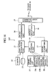
- Fig. 14 is a schematic block diagram showing an exemplary configuration of a transmitting terminal device in the communication system of Fig. 13.
- Fig. 15 is a flow chart for a control of a transmission rate according to a congestion state of a transmission path in the communication system of Fig. 11.
- Fig. 16 is a block diagram showing an exemplary configuration of a conventional communication system.
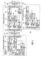
- Fig. 1 shows a configuration of a communication system according to this embodiment.
- This communication system comprises a transmitting terminal device 10 for transmitting data packets (RT packets) for audio data or video data, for example, in real time, a relay device 20 connected with the transmitting terminal device 10 through a wired channel (transmission path), for example, for relaying the data packets from the transmitting terminal device 10, a packet analysis device 30 for analyzing a transmission state of the data packets from the transmitting terminal device 10, a base station 40 for relaying the data packets from the transmitting terminal device 10 through a radio channel (transmission path), and a receiving terminal device 50 for receiving the data packets from the transmitting terminal device 10 that are supplied through the base station 40.
- a transmitting terminal device 10 for transmitting data packets (RT packets) for audio data or video data, for example, in real time
- a relay device 20 connected with the transmitting terminal device 10 through a wired channel (transmission path), for example, for relaying the data packets from the transmitting terminal device 10, a packet analysis device 30 for analyzing a transmission state of the data packets
- the exemplary case of using an RTCP report as information for indicating the transmission state of the data packets is not limited to this particular form, and it is possible to use a message or the like in the other format as long as it contains information for indicating the transmission state such as a packet loss rate, a delay jitter, etc.
- the transmitting terminal device 10 is an information processing device such as PC (Personal Computer) equipped with CPU, memory, etc., for example.
- PC Personal Computer
- This transmitting terminal device 10 has a data packet generation unit 13 for generating data packets for video signal data from a camera 11, for example, or video data, audio data, etc., that are stored in a hard disk drive (HDD) device 12, a packet transmission unit 14 for transmitting packets to the relay device 20, a communication interface 15 for carrying out communications with the relay device 20, a packet reception unit 16 for receiving packets from the relay device 20, a report classifying unit 17 for extracting the RTCP report from the packets received by the packet reception unit 16, a report storing unit 18 for storing the RTCP report extracted by the report classifying unit 17, and a QoS (Quality of Service) control unit 19 for controlling qualities of the communications such as a transmission rate according to the RTCP report from the receiving terminal device 50.
- each one of the data packet generation unit 13, the report classifying unit 17, and the QoS control unit 19 can be realized in a form of hardware or software.
- the relay device 20 is connected with the transmitting terminal device 10 and the packet analysis device 30 through wired channels, and has communication interfaces (not shown) for carrying out communications with the transmitting terminal device 10 and the packet analysis device 30, and a route control unit (not shown) for controlling relay routes.
- the packet analysis device 30 has a communication interface 31 for carrying out communications with the relay device 20, a packet reception unit 32 for receiving packets from the relay device 20, a data packet extraction unit 33 for extracting data packets from packets received by the packet reception unit 32, a packet transmission unit 34 for transmitting packets to the base station 40, a communication interface 35 for carrying out communications with the base station 40, a statistical information calculation unit 36 for analyzing a transmission state of the data packets extracted by the data packet extraction unit 33, a report generation unit 37 for generating the RTCP report according to the transmission state of the data packets, a packet reception unit 38 for receiving packets from the base station 40, and a packet transmission unit 39 for transmitting packets to the relay device 20.
- each one of the data packet extraction unit 33, the statistical information calculation unit 36, and the report generation unit 37 can be realized in a form of hardware or software.
- the base station 40 is connected with the packet analysis device 30 through a wired channel and with the receiving terminal device 50 through a radio channel. For this reason, the base station 40 has a communication interface (not shown) for carrying out communications with the packet analysis device 30 through the wired channel, a communication interface (not shown) for carrying out communications with the receiving terminal device 50 through the radio channel, and a route selection control unit (not shown) for selecting a relay route.
- the receiving terminal device 50 is an information processing device such as portable telephone, PC, or PDA (Personal Digital Assistant) equipped with CPU, memory, etc., for example.
- PDA Personal Digital Assistant
- This receiving terminal device 50 has a communication interface 51 for carrying out communications with the base station 40, a packet reception unit 52 for receiving packets from the base station 40, a data packet extraction unit 53 for extracting data packets from packets received by the packet reception unit 52, a presentation unit 54 for making audio or video presentation of according to the audio data or video data contained in the data packets extracted by the data packet extraction unit 53, a statistical information calculation unit 55 for analyzing a transmission state of the data packets extracted by the data packet extraction unit 53, a report generation unit 56 for generating the RTCP report according to the transmission state of the data packets, and a packet transmission unit 57 for transmitting packets to the base station 40.
- each one of the data packet extraction unit 53, the statistical information calculation unit 55, and the report generation unit 56 can be realized in a form of hardware or software.
- the data packet generation unit 13 of the transmitting terminal device 10 generates the data packets for the video signal data from the camera 11 or the video data, audio data, etc., that are stored in the hard disk drive (HDD) device 12 at a prescribed transmission rate that is set up by the control from the QoS control unit 19.
- HDD hard disk drive
- This data packet generation unit 13 generates the data packets according to the RTP packet format as specified by the RTP (Real-time Transport Protocol) defined by the RFC 1889, for example.
- RTP Real-time Transport Protocol
- This RTP packet comprises an RTP header containing an identification information of the transmitting terminal device 10 and the receiving terminal device 50, and a payload containing data such as audio data, video data, etc.
- the RTP header contains a version (V), a padding (P), an extension (X), a CSRC (Contributing Source) count (CC), a marker (M), a payload type (PT) for indicating a type of data in the payload (for distinguishing audio data and video data, for example), a sequence number, a timestamp, an SSRC (Synchronization Source) identifier for identifying a device to be used as a reference in the synchronized transmission, and a CSRC (Contributing Source) identifier for identifying a related device.
- the packet transmission unit 14 constructs a UDP (User Datagram Protocol) packet by attaching a UDP header containing transmitting side and receiving side port numbers, to the RTP packet generated according to such a format.
- the packet transmission unit 14 constructs an IP packet by attaching an IP header containing IF addresses of the transmitting side device (the transmitting terminal device 10) and a receiving side device (the receiving terminal device 50), to the UDP packet so constructed, and supplies it to the communication interface 15.
- UDP User Datagram Protocol
- the communication interface 15 transmits the constructed IP packet to the relay device 20 through the communication channel.
- the transmitted IP packet is then supplied to the communication interface 51 of the receiving terminal device 50 through the relay device 20, the packet analysis device 30 and the base station 40 according to the destination address.
- the packet reception unit 52 extracts the UDP packet from the 1P packet, extracts the RTP packet according to the port numbers contained in the UDP header of the UDP packet and supplies it to the data packet extraction unit 53.
- the data packet extraction unit 53 reproduces the audio data, video data, etc., according to the payload type (PT) contained in the RTP header, for example, and supplies them into the presentation unit 54 and the statistical information calculation unit 55.
- the presentation unit 54 reproduces the audio sounds when data supplied from the data packet extraction unit 53 is the audio data, or reproduces the video images when data supplied from the data packet extraction unit 53 is the video data.
- the statistical information calculation unit 55 calculates the number of packets, the number of lost packets, the delay, the delay jitter, etc., of the supplied RTP packets.
- the number of lost packets and the delay Jitter can be obtained from the sequence numbers and the timestamps contained in the RTP headers.
- the statistical information calculation unit 55 obtains the packet loss rate indicating a rate of the lost packets from the number of lost packets within a prescribed period of time, for example.
- the report generation unit 56 generates the RTCP report indicating the transmission state of the RTP packets according to the calculation result obtained by the statistical information calculation unit 55 and supplies it to the packet transmission unit 57, at a prescribed interval.
- the RTCP report contains at least the packet loss rate and the delay jitter, along with the sequence number, the timestamp, etc., of the most recently received RTP packet. Also, this RTCP report is generated as the RTP packet described above, and the packet transmission unit 57 constructs the IP packet by attaching a UDP header, an IP header, etc., to this RTP packet and transmits it to the transmitting terminal device 10 through the communication interface 51.
- This IP packet is supplied to the communication interface 15 of the transmitting terminal device 10 through the base station 40, the packet analysis device 30 and the relay device 20.
- the packet reception unit 16 extracts the UDP packet from the received IP packet, extracts the RTCP report from the UDP packet and supplies it to the report classifying unit 17.
- the report classifying unit 17 stores the supplied RTCP report into a prescribed region (a region 18a for storing the RTCP report from the receiving terminal device 50 in this case) of the report storing unit 18.
- the source of the RTCP report can be Judged according to the IP address or the port number of the source described in the IP packet that contained the RTCP report, or the SSRC identifier described in the RTP header of the RTCP report, etc.
- the RTCP report contains parameters such as the packet loss rate, the delay jitter, etc., as described above, so that the report classifying unit 17 classifies the RTCP report according to these parameters and stores it into the region 18a of the report storing unit 18.
- a value of the parameter of each RTCP report to be stored in the report storing unit 18 can be a value given in the RTCP report supplied from the report classifying unit 17, or a weighted average value of the already stored parameter value and the new parameter value.
- the packet analysis device 30 is also transmitting the transmission state of the received RTP packets as the RTCP report to the transmitting terminal device 10.
- the packet analysis device 30 when the IP packet is supplied to the communication interface 31, the packet reception unit 32 supplies this IP packet to the data packet extraction unit 33,
- the data packet extraction unit 33 Judges whether the supplied packet is one for which there is a need to obtain the statistical information at the statistical information calculation unit 36 or not. This judgement can be made, for example, according to the IP address and the protocol number described in the IP packet, the destination port number described in the UDP packet extracted from the IP packet, the payload type and the SSRC identifier described in the RTP header, etc. For instance, when it is destined to the IF address of the receiving terminal device 50 and it has the port number that is used for the transmission of the RTP packets, it can be Judged as the IP packet for which there is a need to obtain the statistical information.
- the data packet extraction unit 33 supplies the IP packet for which there is no need to obtain the statistical information as it is to the packet transmission unit 34, or supplies the IP packet for which there is a need to obtain the statistical information to the packet transmission unit 34 as well as to the statistical information calculation unit 36.
- the statistical information calculation unit 36 calculates the number of packets, the number of lost packets, the delay, the delay Jitter, etc., of the supplied RTP packets.
- the report generation unit 37 generates the RTCP report indicating the transmission state of the RTP packets according to the calculation result obtained by the statistical information calculation unit 36 and supplies it to the packet transmission unit 39, at a prescribed interval.
- the packet transmission unit 39 constructs the IP packet by attaching a UDP header, an IP header, etc., to the supplied RTP report and transmits it to the transmitting terminal device 10 through the communication interface 31. Note that, when the IP packet received by the packet reception unit 38 is supplied, the packet transmission unit 39 transmits this IP packet as it is to the relay device 20.
- the IP packet transmitted by the packet transmission unit 39 is supplied to the communication interface 15 of the transmitting terminal device 10 through the relay device 20.
- the packet reception unit 16 extracts the UDP packet from the received IP packet, extracts the RTCP report from the UDP packet and supplies it to the report classifying unit 17.
- the report classifying unit 17 stores the supplied RTCP report into a prescribed region (a region 18b for storing the RTCP report from the packet analysis device 30 in this case) of the report storing unit 18. More specifically, the report classifying unit 17 classifies the RTCP report according to the parameters such as the packet loss rate, the delay Jitter, etc., and stores it into the region 18b of the report storing unit 18.
- the QoS control unit 19 controls the qualities of the data packets generated by the data packet generation unit 13 according to the congestion state of the transmission path and the transmission state on bases of the RTCP reports stored in the regions 18a and 18b of the report storing unit 18.
- the qualities include a transmission rate and an error tolerance of the data packets generated by the data packet generation unit 13, for example.
- the QoS control unit 19 analyzes the congestion state of the transmission path between the transmitting terminal device 10 and the packet analysis device 30 and the transmission state between the packet analysis device 30 and the receiving terminal device 50, for example, and controls the qualities such as the transmission rate and the error tolerance of the data packets appropriately according to the congestion state and the transmission state.
- the data packet generation unit 13 changes the qualities such as the transmission rate and the error tolerance of the data packets to be generated according to the control from the QoS control unit 19.
- Fig. 4 schematically shows a flow of the RTP packets from the transmitting terminal device 10 to the receiving terminal device 50 and a flow of the RTCP report from the packet analysis device 30 and the receiving terminal device 50 to the transmitting terminal device 10 as described above,
- the control of the transmission rate by the QoS control unit 19 is carried out by detecting the congestion state of the transmission path according to the RTCP report from the packet analysis device 30 stored in the region 18b and lowering the transmission rate when the transmission path is congested or raising the transmission rate when the transmission path is not congested.
- Fig, 3 shows a processing procedure for such a control of the transmission rate of the data packets according to the congestion state. This processing is carried out starting from the step S1 of Fig. 3 whenever the data packet generation unit 13 generates one unit of the data packets, for example.
- the packet loss rate and the delay jitter at the packet analysis device 30 are denoted as Lp and Jp, respectively, the packet loss rate parameters are denoted as L1 and L2, while the delay jitter parameters are denoted as J1 and J2.
- the QoS control unit 19 judges whether the packet loss rate Lp is greater than L1 or not, or whether the delay jitter Jp is greater than J1 or not, When either the packet loss rate Lp or the delay jitter Jp is greater than the respective one of L1 and J1, it can be regarded that the transmission path (wired channel) between the transmitting terminal device 10 and the packet analysis device 30 is congested, so that the QoS control unit 19 commands the lowering of the transmission rate of the data packets to the data packet generation unit 13 at the step S2, and the processing for this time is terminated.
- the QoS control unit 19 commands to lower a sampling rate or reduce the number of sample bits in the case of the audio data. Also, the QoS control unit 19 commands to reduce the number of frames per unit time or lower a spatial resolution in the case of the video data. Else, a plurality of files using a plurality of coding rates are provided in advance for one data and the QoS control unit 19 selects the file with the lower coding rate.
- the processing proceeds from the step S1 to the step S3, where the QoS control unit 19 judges whether the packet loss rate Lp is less than L2 or not and whether the delay jitter Jp is less than J2 or not.
- the QoS control unit 19 judges whether the packet loss rate Lp is less than L2 or not and whether the delay jitter Jp is less than J2 or not.
- the QoS control unit 19 commands to raise a sampling rate or increase the number of sample bits in the case of the audio data. Also, the QoS control unit 19 commands to increase the number of frames per unit time or raise a spatial resolution, or select the file with the higher coding rate in the case of the video data.
- the processing proceeds from the step S3 to the step S5, where the QoS control unit 19 commands to maintain the current transmission rate of the data packets to the data packet generation unit 13, and the processing for this time is terminated.
- the optimal control of the transmission rate according to the congestion state of the transmission path is carried out in this communication system. For this reason, it is possible to eliminate the unnecessary lowering of the qualities of the data packets, and it is also possible to relax the congestion of the network.
- the congestion state of the transmission path has been analyzed by using the packet loss rate, the delay jitter, etc., contained in the RTCP report from the receiving terminal device, for example. Consequently, when the channel with a poor transmission state such as a radio channel is involved in the transmission path, the transmission path can be judged as congested even in the case of the packet loss and the delay jitter that are caused by the transmission state. As a result, there have been cases where the transmission rate at the transmitting side is lowered more than necessary.
- the congestion state of the transmission path is analyzed by using the packet loss rate, the delay jitter, etc., contained in the RTCP report from the packet analysis device 30 where no radio channel with a poor transmission state is involved between the packet analysis device 30 and the transmitting terminal device 10, so that it is possible to comprehend the actual congestion state of the transmission path. For this reason, it is possible to prevent the lowering of the transmission rate more than necessary.
- control of the error tolerance by the QoS control unit 19 is carried out by detecting the transmission state of the transmission path between the packet analysis device 30 and the receiving terminal device 50 according to the RTCP report from the packet analysis device 30 and the RTCP report from the receiving terminal device 50, and raising the error tolerance when the transmission state is poor and there are many errors or lowering the error tolerance when the transmission state is good and there are only few errors.
- the transmission path between the packet analysis device 30 and the receiving terminal device 50 is formed by the wired channel from the packet analysis device 30 to the base station 40 and the radio channel from the base station 40 to the receiving terminal device 50.
- the transmission state is expected to be poorer in the radio channel, so that it is expected that the transmission state between the packet analysis device 30 and the receiving terminal device 50 is largely influenced by the radio channel between the base station 40 and the receiving terminal device 50.
- the packet loss rate due to the radio channel can be estimated as a difference (Lr-Lp) between the packet loss rate Lr at the receiving terminal device 50 and the packet loss rate Lp at the packet analysis device 30, with a negligible error.
- this difference is set as the estimated packet loss rate (Lr-Lp) at the radio channel, and the error tolerance of the data packets generated by the data packet generation unit 13 is changed according to this estimated packet loss rate.
- the transmission frequencies of I-picture, VOP (Video Object Plane) header, HEC (Header Extension Code), etc. are changed according to the estimated packet loss rate. For instance, as shown in Fig. 5, the transmission frequency of the I-picture is increased as the estimated packet loss rate becomes higher. In this way, it is possible to improve the error tolerance in the case of losing some I-pictures due to the packet loss.
- a plurality of files with different error tolerances can be provided in advance, and as shown in Fig. 6, the file with the higher error tolerance can be selected as the estimated packet loss rate becomes higher, for example. Note that, in Fig. 6, it is assumed that the error tolerance becomes higher in the order of the file A, the file B and the file C. In this way, it is possible to select the file with the appropriate error tolerance according to the packet loss rate.
- the FEC (Forward Error Correction) packet specified by the RFC 2733 as a data packet as shown in Fig. 7, for example can be transmitted at a prescribed frequency, and the transmission frequency of the FEC packet can be increased as the estimated packet loss rate becomes higher. In this way, it is possible to transmit the data packet with the appropriate error tolerance according to the estimated packet loss rate.
- the packet loss rate of the radio channel between the base station 40 and the receiving terminal device 50 i.e., a channel that is expected to have the poorest transmission state between the transmission terminal device 10 and the receiving terminal device 50
- the error tolerance of the data packets it is possible to reduce the degradation of the data packets due to the packet loss and it is also possible to minimize the overhead due to the error tolerance.
- the packets received by the packet reception unit 32 are directly supplied to the data packet extraction unit 33, but as shown in Fig. 8, for example, it is also possible to provide a traffic control unit 301 for controlling the traffic of the packets received by the packet reception unit 32.
- This traffic control unit 301 functions as a buffer for carrying out a conversion of the transmission rate of the packets from the transmitting terminal device 10 and the transmission rate of the packets with respect to the receiving terminal device 50. Namely, the transmission rate of the input packets with respect to the traffic control unit 301 is set to coincide with the transmission rate of the transmitting terminal device 10, and the transmission rate of the output packets from the traffic control unit 301 is set to coincide with the transmission rate with respect to the receiving terminal device 50 or the transmission rate with respect to the base station 40.
- the packet analysis device 30 can carry out the analysis of the congestion state of the transmission path from the transmitting terminal device 10 to the packet analysis device 30 similarly as described above, for the purpose of transmitting the RTCP report to the transmitting terminal device 10 similarly as described above.
- the transmission rate of the data packets to be supplied to the base station 40 can be set to be a transmission rate according to the transmission rate (error quality) of the radio channel, so that the congestion in the radio channel can be suppressed.
- a traffic control device 60 for controlling the traffic between the relay device 20 and the packet analysis device 30
- This traffic control device 60 also functions as a buffer for carrying out a conversion of the transmission rate of the packets from the transmitting terminal device 10 and the transmission rate of the packets with respect to the receiving terminal device 50, similarly as the traffic control unit 301 described above.
- the transmission rate of the data packets supplied to the packet analysis device 30 is set to coincide with the transmission rate with respect to the receiving terminal device 50 or the transmission rate with respect to the base station 40.
- the packet analysis device 30 generates the RTCP report described above for the data packets that are supplied at this transmission rate, and supplies the RTCP report to the transmitting terminal device 10.
- the packet analysis device 30 may not be provided with a function for carrying out the relay of the data packets as described above, and it is possible to use a configuration in which the packet transmission unit 34, the communication interface 35 and the packet reception unit 38 are omitted, for example.
- the packet analysis device 30 in this case can also be realized by the receiving terminal device having functions for receiving the multicast packets and transmitting the RTCP report for the received packets, which is provided adjacent to the relay device 70, for example,
- the communication system shown in Fig. 1 has a configuration in which the radio channel exists on the receiving terminal device 50 side, but as shown in Fig. 11, for example, it is also possible to use a configuration in which the radio channel exists on a transmitting terminal device 110 side.
- the transmitting terminal device 110 has the camera 11 to the packet transmission unit 14 and the packet reception unit 16 to the QoS control unit 19 similarly as the transmitting terminal device 10 described above, as well as a function for carrying out communications with a base station 80 through the radio channel instead of the communication interface 15.
- a receiving terminal device 150 has the packet reception unit 52 to the packet transmission unit 57 similarly as the receiving terminal device 50 described above, as well as a function for carrying out communications with a relay device 90 through the wired channel instead of the communication interface 51.
- the packet analysis device 30 and the receiving terminal device 150 transmit the RTCP reports to the transmitting terminal device 110 according to the transmission states of the received RTP packets similarly as described above, and the RTCP report from the packet analysis device 30 is stored into the region 18b while the RTCP report from the receiving terminal device 150 is stored into the region 18a.
- the QoS control unit 19 estimates the transmission state (error quality) of the radio channel between the transmitting terminal device 110 and the base station 80 according to the RTCP report from the packet analysis device 30 that is stored in the region 18b.
- the QoS control unit 19 also estimates the congestion state of the wired channel between the packet analysis device 30 and the receiving terminal device 150 according to the RTCP report from the receiving terminal device 150 that is stored in the region 18a and the RTCP report from the packet analysis device 30 that is stored in the region 18b.
- the QoS control unit 19 changes the transmission rate and the error tolerance of the data packets to be generated by the data packet generation unit 13 according to the transmission state and the congestion state.
- Fig. 12 shows a processing procedure for the control of the transmission rate of the data packets in this communication system. This processing is carried out starting from the step S11 of Fig. 12 whenever the data packet generation unit 13 generates one unit of the data packets, for example.
- the packet loss rate and the delay jitter at the packet analysis device 30 are denoted as Lp and Jp, respectively
- the packet loss rate and the delay jitter at the receiving terminal device 150 are denoted as Lr and Jr, respectively
- the packet loss rate parameters are denoted as L3 and L4
- the delay jitter parameters are denoted as J3 and J4.
- the QoS control unit 19 obtains a difference (Lr-Lp) between the packet loss rate Lr of the receiving terminal device 150 and the packet loss rate Lp of the packet analysis device 30, and a difference (Jr-Jp) between the delay jitter Jr of the receiving terminal device 150 and the delay jitter Jp of the packet analysis device 30, in order to analyze the congestion state of the wired channel between the packet analysis device 30 and the receiving terminal device 150.
- the QoS control unit 19 judges whether the difference (Lr-Lp) of the packet loss rates is greater than L3 or not and whether the difference (Jr-Jp) of the delay jitters is greater than J3 or not.
- the difference (Lr-Lp) of the packet loss rates or the difference (Jr-Jp) of the delay jitters is greater than the respective one of L3 and J3, it can be regarded that the transmission path (wired channel) between the packet analysis device 30 and the receiving terminal device 150 is congested, so that the QoS control unit 19 commands the lowering of the transmission rate of the data packets to the data packet generation unit 13 at the step S12, and the processing for this time is terminated.
- the processing proceeds from the step S11 to the step S13, where the QoS control unit 19 judges whether the difference (Lr-Lp) of the packet loss rates is less than L4 or not and whether the difference (Jr-Jp) of the delay jitters is less than J4 or not.
- the processing proceeds from the step S13 to the step S15, where the QoS control unit 19 commands to maintain the current transmission rate of the data packets to the data packet generation unit 13, and the processing for this time is terminated.
- the optimal control of the transmission rate according to the congestion state of the transmission path is carried out in this communication system, similarly as in the communication system of Fig. 1 described above.
- the QoS control unit 19 carries out the control of the error tolerance by estimating the transmission state (error quality) of the radio channel between the transmitting terminal device 110 and the base station 80 according to the packet loss rate Lp at the packet analysis unit 30, and raising the error tolerance of the data packets when the transmission state is poor and the packet loss rate Lp is high or lowering the error tolerance of the data packets when the transmission state is good and the packet loss rate Lp is low.
- regions 18b and 18c for storing the RTCP reports from the packet analysis devices 30A and 30B respectively are provided in the report storing unit 18' of the transmitting terminal device 110'.
- the number of the packet analysis devices is not limited to two as shown in Fig. 14, and can be any desired number as long as the corresponding number of regions are provided in the report storing unit 18'.
- the report classifying unit 17 judges the source of the RTCP report according to the IP address or the port number of the source described in the IP packet that contained the RTCP report, or the SSRC identifier described in the RTP header of the RTCP report, etc., similarly as described above, and stores it into the corresponding region 18a, 18b, or 18c.
- each one of the packet analysis devices 30A and 30B and the receiving terminal device 50 transmits the RTCP report to the transmitting terminal device 110', and the transmitting terminal device 110' controls the transmission rate and the error tolerance of the data packets according to each RTCP report.
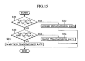
- Fig. 15 shows a processing procedure for the control of the transmission rate of the data packets in this communication system. This processing is carried out starting from the step S21 of Fig. 15 whenever the data packet generation unit 13 generates one unit of the data packets, for example.
- the packet loss rate and the delay jitter at the packet analysis device 30A are denoted as Lpa and Jpa, respectively
- the packet loss rate and the delay Jitter at the packet analysis device 30B are denoted as Lpb and Jpb, respectively
- the packet loss rate and the delay jitter at the receiving terminal device 150 are denoted as Lr and Jr, respectively
- the packet loss rate parameters are denoted as L5 and L6, while the delay Jitter parameters are denoted as J5 and J6.
- the QoS control unit 19 obtains a difference (Lpb-Lpa) between the packet loss rate Lpb of the packet analysis device 30B and the packet loss rate Lpa of the packet analysis device 30A, and a difference (Jpb-Jpa) between the delay jitter Jpb of the packet analysis device 30B and the delay jitter Jpa of the packet analysis device 30A, in order to analyze the congestion state of the wired channel between the packet analysis device 30A and the packet analysis device 30B.
- the QoS control unit 19 judges whether the difference (Lpb-Lpa) of the packet loss rates is greater than L5 or not and whether the difference (Jpb-Jpa) of the delay jitters is greater than J5 or not.
- the difference (Lpb-Lpa) of the packet loss rates or the difference (Jpb-Jpa) of the delay jitters is greater than the respective one of L5 and J5
- the QoS control unit 19 commands the lowering of the transmission rate of the data packets to the data packet generation unit 13 at the step S22, and the processing for this time is terminated.
- the processing proceeds from the step S21 to the step S23, where the QoS control unit 19 judges whether the difference (Lpb-Lpa) of the packet loss rates is less than L6 or not and whether the difference (Jpb-Jpa) of tile delay jitters is less than J6 or not.
- the processing proceeds from the step S23 to the step S25, where the QoS control unit 19 commands to maintain the current transmission rate of the data packets to the data packet generation unit 13, and the processing for this time is terminated.
- the optimal control of the transmission rate according to the congestion state of the transmission path is carried out in this communication system, similarly as in the communication system of Fig. 1 or Fig. 11 described above.
- the QoS control unit 19 carries out the control of the error tolerance by estimating the transmission state (error quality) of the radio channels based on a total of the packet loss rates at the respective radio channels, and raising the error tolerance of the data packets when the transmission state is poor and the total packet loss rate is high or lowering the error tolerance of the data packets when the transmission state is good and the total packet loss rate is low.
- the QoS control unit 19 estimates the packet loss rate of the radio channel between the transmitting terminal device 110' and the base station 80 according to the packet loss rate Lpa at the packet analysis device 30A. and estimates the packet loss rate of the radio channel between the packet analysis device 30B and the receiving terminal device 50 according to the difference (Lr-Lpb) of the packet loss rate Lr at the receiving terminal device 50 and the packet loss rate Lpb at the packet analysis device 30B. Then, a sum (Lr+Lpa-Lpb) of the packet loss rates of these radio channels is set as the total packet loss rate at the radio channels, and the error tolerance of the data packets is changed according to this total packet loss rate.
- the above description is directed to the exemplary case of providing the relay device 20, the packet analysis device 30, the base station 40 and the traffic control device 60 as separate devices, but it is also possible to use a configuration in which a part or a whole of the functions of these devices are provided integrally in one or a plurality of devices.
- the QoS control unit 19 analyzes the state of the transmission path between the transmitting terminal device and the receiving terminal device according to the packet loss rate and the delay jitter described in the RTCP report, and controls the qualities of the data packets to be transmitted according to the analyzed state
- the state of the transmission path according to the other parameters described in the RTCP report such as the number of lost packets and the delay for the RTP packets, for example, and control the qualities of the data packets to be transmitted according to the analyzed state.
- the above description is directed to the exemplary case of controlling the transmission rate and the error tolerance of the data packets, but it is also possible to analyze the congestion state of the wired channel portion according to the packet loss rate at the packet analysis device or the packet loss rates at the packet analysis device and the receiving terminal device, and control only the transmission rate according to the analyzed congestion state.
- the congestion state of the transmission path is analyzed according to the transmission state of the media packets (RT packets) received by the relay device that relays the RT packets from the transmitting terminal device, and the transmission rate of the media packets (RT packets) to be transmitted by the transmitting terminal device is controlled according to the congestion state analysis result, so that it is possible to control the transmission rate of the media packets (RT packets) to be transmitted by the transmitting terminal device according to the congestion state of the transmission path that is analyzed according to the media packets (RT packets) received by the relay device.
- the congestion state of the transmission path between the transmitting terminal device and the receiving terminal device is analyzed, the transmission state of the media packets (RT packets) between the transmitting terminal device and the receiving terminal device is analyzed, and the qualities (the transmission rate, the error tolerance, etc., for example) of the media packets (RT packets) to be transmitted by the transmitting terminal device is controlled according to the transmission path congestion state analysis result and the transmission state analysis result, so that it is possible to control the qualities of the media packets (RT packets) according to the state of the transmission path.
- the qualities the transmission rate, the error tolerance, etc., for example
Landscapes
- Engineering & Computer Science (AREA)
- Computer Networks & Wireless Communication (AREA)
- Signal Processing (AREA)
- Multimedia (AREA)
- Databases & Information Systems (AREA)
- Data Exchanges In Wide-Area Networks (AREA)
- Two-Way Televisions, Distribution Of Moving Picture Or The Like (AREA)
Applications Claiming Priority (2)
| Application Number | Priority Date | Filing Date | Title |
|---|---|---|---|
| JP2001081321 | 2001-03-21 | ||
| JP2001081321A JP3769468B2 (ja) | 2001-03-21 | 2001-03-21 | 通信品質制御方法、通信品質制御システム、パケット解析装置及びデータ送信端末装置 |
Publications (2)
| Publication Number | Publication Date |
|---|---|
| EP1249975A2 true EP1249975A2 (fr) | 2002-10-16 |
| EP1249975A3 EP1249975A3 (fr) | 2009-06-03 |
Family
ID=18937452
Family Applications (1)
| Application Number | Title | Priority Date | Filing Date |
|---|---|---|---|
| EP20020006552 Withdrawn EP1249975A3 (fr) | 2001-03-21 | 2002-03-20 | Procédé de controle de la qualité d'une communication utilisant l'état de la transmission des paquets temps réel et l'état de congestion du chemin de transmission |
Country Status (6)
| Country | Link |
|---|---|
| US (1) | US20020136162A1 (fr) |
| EP (1) | EP1249975A3 (fr) |
| JP (1) | JP3769468B2 (fr) |
| KR (1) | KR100457954B1 (fr) |
| CN (1) | CN100431311C (fr) |
| SG (1) | SG108839A1 (fr) |
Cited By (2)
| Publication number | Priority date | Publication date | Assignee | Title |
|---|---|---|---|---|
| CN100344112C (zh) * | 2004-12-14 | 2007-10-17 | 华为技术有限公司 | 下一代网络中mg上报服务质量信息的实现方法 |
| CN100349411C (zh) * | 2004-06-30 | 2007-11-14 | 华为技术有限公司 | 媒体流服务质量上报方法 |
Families Citing this family (70)
| Publication number | Priority date | Publication date | Assignee | Title |
|---|---|---|---|---|
| JP4544640B2 (ja) * | 2001-03-29 | 2010-09-15 | パナソニック株式会社 | データ再生装置及びデータ再生方法 |
| JP4000905B2 (ja) * | 2002-05-22 | 2007-10-31 | ソニー株式会社 | 情報処理システムおよび方法、情報処理装置および方法、記録媒体、並びにプログラム |
| KR20040020639A (ko) * | 2002-08-31 | 2004-03-09 | 삼성전자주식회사 | 실시간 멀티미디어 데이터 생성율의 동적 제어방법 및 그장치 |
| EP1432174B1 (fr) * | 2002-12-20 | 2011-07-27 | Siemens Enterprise Communications GmbH & Co. KG | Méthode pour l'analyse de la qualité lors de la transmission de données en temps réel dans un réseau de commutation par paquets |
| JP3769752B2 (ja) * | 2002-12-24 | 2006-04-26 | ソニー株式会社 | 情報処理装置および情報処理方法、データ通信システム、並びに、プログラム |
| EP1450535A1 (fr) * | 2003-02-18 | 2004-08-25 | Matsushita Electric Industrial Co., Ltd. | Station relais pour retransmission hierarchiques dans des flux de donnees multimedia |
| CN1531282A (zh) * | 2003-03-12 | 2004-09-22 | ���µ�����ҵ��ʽ���� | 分组中继装置 |
| US7603475B2 (en) * | 2003-03-31 | 2009-10-13 | Alcatel-Lucent Usa Inc. | Method for flow control in a communication system |
| US7640373B2 (en) * | 2003-04-25 | 2009-12-29 | Motorola, Inc. | Method and apparatus for channel quality feedback within a communication system |
| US20040228282A1 (en) * | 2003-05-16 | 2004-11-18 | Qi Bao | Method and apparatus for determining a quality measure of a channel within a communication system |
| US7848229B2 (en) * | 2003-05-16 | 2010-12-07 | Siemens Enterprise Communications, Inc. | System and method for virtual channel selection in IP telephony systems |
| KR100547116B1 (ko) * | 2003-05-23 | 2006-01-26 | 삼성전자주식회사 | 무선 네트워크를 통한 통신 방법 및 그 장치 |
| EP1489865A1 (fr) * | 2003-06-18 | 2004-12-22 | Koninklijke KPN N.V. | Procédé et système d'analyse de la qualité des données pour réseaux de communication sans fil |
| EP1658702B1 (fr) * | 2003-08-28 | 2008-02-27 | Telefonaktiebolaget LM Ericsson (publ) | Systeme et procede de gestion de ressources permettant d'assurer une qualite de service qos dans des reseaux bases sur le protocole internet |
| US8949395B2 (en) | 2004-06-01 | 2015-02-03 | Inmage Systems, Inc. | Systems and methods of event driven recovery management |
| ATE413044T1 (de) * | 2004-06-30 | 2008-11-15 | Huawei Tech Co Ltd | Verfahren zum periodischen akquirieren einer dienstqualität (qos) eines multimedia-streams |
| KR100641159B1 (ko) * | 2004-07-23 | 2006-11-02 | 엘지전자 주식회사 | Rtcp패킷 기반의 적응적 멀티미디어 데이터 전송률추정방법 |
| KR100877172B1 (ko) | 2004-08-02 | 2009-01-07 | 인터디지탈 테크날러지 코포레이션 | 다중 입력 다중 출력(mimo) 직교 주파수 분할다중화(ofdm) 시스템의 품질 제어 방법 |
| US7864659B2 (en) * | 2004-08-02 | 2011-01-04 | Interdigital Technology Corporation | Quality control scheme for multiple-input multiple-output (MIMO) orthogonal frequency division multiplexing (OFDM) systems |
| CN100358291C (zh) * | 2004-09-08 | 2007-12-26 | 华为技术有限公司 | 下一代网络中动态协商服务质量的系统及其实现方法 |
| BRPI0516632A (pt) * | 2004-12-02 | 2008-09-16 | Thomson Licensing | correção de erros antecipada e adaptativa |
| JP4780963B2 (ja) * | 2005-01-07 | 2011-09-28 | 三菱電機株式会社 | 映像配信システム |
| JP2006279784A (ja) | 2005-03-30 | 2006-10-12 | Fujitsu Ltd | エッジスイッチ |
| US7889654B2 (en) | 2005-03-30 | 2011-02-15 | At&T Intellectual Property Ii, L.P. | Loss tolerant transmission control protocol |
| CN1870514A (zh) * | 2005-05-28 | 2006-11-29 | 华为技术有限公司 | 会话服务质量分析的实现方法 |
| US8289370B2 (en) * | 2005-07-20 | 2012-10-16 | Vidyo, Inc. | System and method for scalable and low-delay videoconferencing using scalable video coding |
| US7933294B2 (en) * | 2005-07-20 | 2011-04-26 | Vidyo, Inc. | System and method for low-delay, interactive communication using multiple TCP connections and scalable coding |
| US7701851B2 (en) * | 2005-07-20 | 2010-04-20 | Vidyo, Inc. | System and method for the control of the transmission rate in packet-based digital communications |
| KR101261053B1 (ko) * | 2006-05-18 | 2013-05-06 | 주식회사 케이티 | 점대점 패킷 성능 분석 시스템 및 그 분석 방법 |
| US8681776B2 (en) * | 2006-10-12 | 2014-03-25 | Genband Us Llc | Methods, systems and computer program products for storing communication session information at a network interface module |
| US7953118B2 (en) * | 2006-12-08 | 2011-05-31 | Microsoft Corporation | Synchronizing media streams across multiple devices |
| EP2159976A4 (fr) * | 2007-05-21 | 2014-03-12 | Fujitsu Ltd | Dispositif de relais et procédé de relais |
| JP2009027720A (ja) * | 2007-07-23 | 2009-02-05 | Polycom Inc | 輻輳回避と共に損失パケット回復を行うシステム及び方法 |
| US8812712B2 (en) | 2007-08-24 | 2014-08-19 | Alcatel Lucent | Proxy-driven content rate selection for streaming media servers |
| US20090274226A1 (en) * | 2008-05-05 | 2009-11-05 | Motorola, Inc. | Sounding channel based feedback in a wireless communication system |
| JP5083059B2 (ja) * | 2008-06-18 | 2012-11-28 | 沖電気工業株式会社 | パケット中継装置およびパケット中継方法 |
| CN101364999B (zh) * | 2008-09-18 | 2012-07-04 | 华为技术有限公司 | 一种基于流的服务质量处理的方法、设备及系统 |
| US8315164B2 (en) * | 2008-12-11 | 2012-11-20 | Skype | Controlling packet transmission |
| GB2466208B (en) * | 2008-12-11 | 2013-09-11 | Skype | Controlling packet transmission |
| TWI501608B (zh) * | 2009-01-23 | 2015-09-21 | Ind Tech Res Inst | 資料收集之方法及其主動裝置與從動裝置 |
| CN101854268B (zh) * | 2009-04-04 | 2013-06-05 | 华为技术有限公司 | Ip网络性能测量、服务质量控制的方法、装置和系统 |
| US7995494B2 (en) * | 2009-04-08 | 2011-08-09 | At&T Intellectual Property I, L.P. | Method and apparatus for conducting media quality measurements at a gateway |
| US8341672B2 (en) | 2009-04-24 | 2012-12-25 | Delta Vidyo, Inc | Systems, methods and computer readable media for instant multi-channel video content browsing in digital video distribution systems |
| AU2010270876A1 (en) * | 2009-06-24 | 2011-12-08 | Vidyo, Inc. | System and method for an active video electronic programming guide |
| CN102036061B (zh) * | 2009-09-30 | 2012-11-21 | 华为技术有限公司 | 视频数据传输处理、发送处理方法、装置和网络系统 |
| KR101680868B1 (ko) * | 2009-11-18 | 2016-11-30 | 삼성전자주식회사 | 무선통신시스템에서의 데이터 전송 제어장치 및 방법 |
| WO2011066105A1 (fr) * | 2009-11-25 | 2011-06-03 | Delta Vidyo, Inc. | Protocole d'interaction et de présence de télévision sur ip |
| CN102656931A (zh) * | 2009-12-18 | 2012-09-05 | 株式会社Ntt都科摩 | 无线基站以及中继装置 |
| KR101705359B1 (ko) * | 2010-03-12 | 2017-02-10 | 경희대학교 산학협력단 | 네트워크에서 서비스 품질 제어 관련 정보를 보고하는 방법과 이를 위한 네트워크 엔터티 |
| JP5515978B2 (ja) * | 2010-03-31 | 2014-06-11 | ソニー株式会社 | 通信装置、通信方法およびプログラム |
| US9338483B2 (en) | 2010-06-11 | 2016-05-10 | Sony Corporation | Camera system, video selection apparatus and video selection method |
| JP2011259365A (ja) * | 2010-06-11 | 2011-12-22 | Sony Corp | カメラシステム、映像選択装置及び映像選択方法 |
| US8520699B2 (en) * | 2010-12-09 | 2013-08-27 | Qualcomm Incorporated | Apparatus and methods for providing a communication quality feedback of an end-to-end communication path |
| AU2012225513B2 (en) | 2011-03-10 | 2016-06-23 | Vidyo, Inc. | Dependency parameter set for scalable video coding |
| US20130195119A1 (en) * | 2011-10-14 | 2013-08-01 | Qualcomm Incorporated | Feedback channel for wireless display devices |
| EP2587824A1 (fr) * | 2011-10-27 | 2013-05-01 | Thomson Licensing | Procédé et appareil pour la gestion du fonctionnement d'un client de diffusion adaptative |
| US9313486B2 (en) | 2012-06-20 | 2016-04-12 | Vidyo, Inc. | Hybrid video coding techniques |
| US9439100B2 (en) * | 2012-06-27 | 2016-09-06 | Aruba Networks, Inc. | System and method for dynamic rate adaptation based on real-time call quality metrics |
| CN102801624B (zh) * | 2012-08-16 | 2015-03-04 | 中国人民解放军信息工程大学 | 一种网络数据流抽样方法及装置 |
| JP2014081831A (ja) * | 2012-10-17 | 2014-05-08 | Denso Corp | 画像情報を用いた車両用運転支援システム |
| JP5976934B2 (ja) * | 2013-06-28 | 2016-08-24 | 株式会社東芝 | 電子機器 |
| EP2827522A1 (fr) * | 2013-07-15 | 2015-01-21 | Alcatel Lucent | Procédé pour un premier n'ud de réseau pour transmission ou retransmission de données vers un second n'ud de réseau et premier n'ud de réseau correspondant et procédé destiné à un second n'ud de réseau pour recevoir des données transmises ou retransmises depuis un premier n'ud de réseau et second n'ud de réseau associé |
| US9456378B2 (en) * | 2013-09-25 | 2016-09-27 | Intel Corporation | End-to-end (E2E) tunneling for multi-radio access technology (multi-rat) |
| WO2015093912A1 (fr) | 2013-12-20 | 2015-06-25 | 삼성전자 주식회사 | Procédé et dispositif de régulation de l'encombrement dans un système de communication mobile |
| KR20150073825A (ko) * | 2013-12-20 | 2015-07-01 | 삼성전자주식회사 | 이동 통신 시스템에서 음성 호 설정 시간을 단축시키는 방법 및 장치 |
| JP2016012843A (ja) * | 2014-06-30 | 2016-01-21 | 株式会社リコー | 伝送管理システム、伝送システム、伝送管理方法、伝送方法、及びプログラム |
| US9558078B2 (en) | 2014-10-28 | 2017-01-31 | Microsoft Technology Licensing, Llc | Point in time database restore from storage snapshots |
| JP2016167657A (ja) * | 2015-03-09 | 2016-09-15 | 株式会社リコー | 伝送管理システム、伝送システム、伝送管理方法、及びプログラム |
| US11190317B2 (en) * | 2017-08-08 | 2021-11-30 | Sony Corporation | Transmitting terminal, transmitting method, information processing terminal, and information processing method |
| KR102471228B1 (ko) * | 2022-04-04 | 2022-11-28 | 서울대학교산학협력단 | 네트워크의 패킷 흐름에 대한 공격성 파라미터 동적 제어 방법 및 장치 |
Citations (2)
| Publication number | Priority date | Publication date | Assignee | Title |
|---|---|---|---|---|
| EP0651531A2 (fr) | 1993-10-29 | 1995-05-03 | AT&T Corp. | Technique de communication utilisant un débit variable de transmission d'information fonction de la qualité |
| WO1997022196A1 (fr) | 1995-12-11 | 1997-06-19 | Nokia Telecommunications Oy | Adaptation du debit dans un canal de donnees non transparent et non uniforme |
Family Cites Families (17)
| Publication number | Priority date | Publication date | Assignee | Title |
|---|---|---|---|---|
| US1832389A (en) * | 1930-02-17 | 1931-11-17 | S H G Inc | Heating unit |
| US5040171A (en) * | 1989-01-24 | 1991-08-13 | Kabushiki Kaisha Toshiba | Call restricting method in packet switching network and network controller having call restricting function |
| US5319638A (en) * | 1991-09-12 | 1994-06-07 | Bell Communications Research, Inc. | Link-by-link congestion control for packet transmission systems |
| US5497504A (en) * | 1994-05-13 | 1996-03-05 | The Trustees Of Columbia University | System and method for connection control in mobile communications |
| US6075768A (en) * | 1995-11-09 | 2000-06-13 | At&T Corporation | Fair bandwidth sharing for video traffic sources using distributed feedback control |
| JP3075188B2 (ja) * | 1996-08-30 | 2000-08-07 | 日本電気株式会社 | セルレート監視装置 |
| US5995488A (en) * | 1996-10-08 | 1999-11-30 | Advanced Micro Devices, Inc. | Method and apparatus for regulating data flow in networks |
| JPH10247944A (ja) * | 1997-03-05 | 1998-09-14 | Kokusai Denshin Denwa Co Ltd <Kdd> | 中継制御装置および方法 |
| US6091709A (en) * | 1997-11-25 | 2000-07-18 | International Business Machines Corporation | Quality of service management for packet switched networks |
| US6075769A (en) * | 1997-11-26 | 2000-06-13 | Cisco Systems, Inc. | Method and apparatus for network flow control |
| US6212399B1 (en) * | 1998-03-06 | 2001-04-03 | Lucent Technologies, Inc. | Method and apparatus for controlling the power radiated by a wireless terminal in a telecommunications system based on a variable step size |
| JPH11284588A (ja) * | 1998-03-27 | 1999-10-15 | Yamaha Corp | 通信装置、通信方法及びプログラムを記録した媒体 |
| US6643496B1 (en) * | 1998-03-31 | 2003-11-04 | Canon Kabushiki Kaisha | System, method, and apparatus for adjusting packet transmission rates based on dynamic evaluation of network characteristics |
| US6275471B1 (en) * | 1998-05-12 | 2001-08-14 | Panasonic Technologies, Inc. | Method for reliable real-time multimedia streaming |
| DE69927339T2 (de) * | 1998-11-30 | 2006-06-22 | Matsushita Electric Industrial Co., Ltd., Kadoma | Datenübertragungverfahren |
| US6678250B1 (en) * | 1999-02-19 | 2004-01-13 | 3Com Corporation | Method and system for monitoring and management of the performance of real-time networks |
| US6757256B1 (en) * | 1999-08-10 | 2004-06-29 | Texas Instruments Incorporated | Process of sending packets of real-time information |
-
2001
- 2001-03-21 JP JP2001081321A patent/JP3769468B2/ja not_active Expired - Fee Related
-
2002
- 2002-03-19 KR KR10-2002-0014732A patent/KR100457954B1/ko not_active Expired - Fee Related
- 2002-03-20 US US10/100,906 patent/US20020136162A1/en not_active Abandoned
- 2002-03-20 CN CNB021073961A patent/CN100431311C/zh not_active Expired - Fee Related
- 2002-03-20 EP EP20020006552 patent/EP1249975A3/fr not_active Withdrawn
- 2002-03-21 SG SG200201692A patent/SG108839A1/en unknown
Patent Citations (2)
| Publication number | Priority date | Publication date | Assignee | Title |
|---|---|---|---|---|
| EP0651531A2 (fr) | 1993-10-29 | 1995-05-03 | AT&T Corp. | Technique de communication utilisant un débit variable de transmission d'information fonction de la qualité |
| WO1997022196A1 (fr) | 1995-12-11 | 1997-06-19 | Nokia Telecommunications Oy | Adaptation du debit dans un canal de donnees non transparent et non uniforme |
Cited By (2)
| Publication number | Priority date | Publication date | Assignee | Title |
|---|---|---|---|---|
| CN100349411C (zh) * | 2004-06-30 | 2007-11-14 | 华为技术有限公司 | 媒体流服务质量上报方法 |
| CN100344112C (zh) * | 2004-12-14 | 2007-10-17 | 华为技术有限公司 | 下一代网络中mg上报服务质量信息的实现方法 |
Also Published As
| Publication number | Publication date |
|---|---|
| JP3769468B2 (ja) | 2006-04-26 |
| KR100457954B1 (ko) | 2004-11-18 |
| US20020136162A1 (en) | 2002-09-26 |
| EP1249975A3 (fr) | 2009-06-03 |
| JP2002281078A (ja) | 2002-09-27 |
| CN1375966A (zh) | 2002-10-23 |
| CN100431311C (zh) | 2008-11-05 |
| KR20020075246A (ko) | 2002-10-04 |
| SG108839A1 (en) | 2005-02-28 |
Similar Documents
| Publication | Publication Date | Title |
|---|---|---|
| EP1249975A2 (fr) | Procédé de controle de la qualité d'une communication utilisant l'état de la transmission des paquets temps réel et l'état de congestion du chemin de transmission | |
| US7301928B2 (en) | Wireless packet transfer apparatus and method | |
| US6556587B1 (en) | Update of header compression state in packet communications | |
| KR100608821B1 (ko) | 휴대단말기의 왕복지연시간 측정장치 및 방법 | |
| US9742650B2 (en) | Systems and methods for measuring available capacity and tight link capacity of IP paths from a single endpoint | |
| EP1719302B1 (fr) | Procede pour signalisation rapide dans un gestion de la qualite de service dans un services en continu dans un reseau de telecommunications mobile | |
| JP5351170B2 (ja) | 無線パケットネットワークにおける効率的なマルチメディア伝達のための方法および構成 | |
| EP1434378A2 (fr) | Dispositif de traitement d'information, méthode de traitement d'information, système de communication de données et programme de communication de données | |
| JP2004129275A (ja) | Rtcpsr/rrパケット情報を使用してrtpストリームを監視するシステム及び方法 | |
| JP2004186892A (ja) | パケット送信方式及びパケット受信方式 | |
| JP5147858B2 (ja) | 複合および非複合rtcpパケット間のrtcp帯域幅の分割 | |
| US6665291B1 (en) | Method and system for carrying data, voice and video across an internet protocol based wireless telecommunications network | |
| EP2022201B1 (fr) | Surveillance de segment multimédia | |
| JP4217121B2 (ja) | Ipネットワークシステムにおける音声品質評価方法および音声品質調整装置 | |
| US7191370B2 (en) | Data transmitter device, repeater device, data transmission/reception device, and data communication method | |
| JP4744457B2 (ja) | 通信方法および通信装置 | |
| US8539064B1 (en) | Analysis of encrypted streaming media traffic | |
| Gruen et al. | Interactive RTP services with predictable reliability | |
| KR20070103660A (ko) | QoS 보장 방법 및 장치 | |
| US20060209872A1 (en) | IP telephone apparatus and IP adapter apparatus | |
| JP2009100437A (ja) | パケット中継交換装置、方法及びプログラム |
Legal Events
| Date | Code | Title | Description |
|---|---|---|---|
| PUAI | Public reference made under article 153(3) epc to a published international application that has entered the european phase |
Free format text: ORIGINAL CODE: 0009012 |
|
| 17P | Request for examination filed |
Effective date: 20020320 |
|
| AK | Designated contracting states |
Kind code of ref document: A2 Designated state(s): AT BE CH CY DE DK ES FI FR GB GR IE IT LI LU MC NL PT SE TR |
|
| AX | Request for extension of the european patent |
Free format text: AL;LT;LV;MK;RO;SI |
|
| PUAL | Search report despatched |
Free format text: ORIGINAL CODE: 0009013 |
|
| AK | Designated contracting states |
Kind code of ref document: A3 Designated state(s): AT BE CH CY DE DK ES FI FR GB GR IE IT LI LU MC NL PT SE TR |
|
| AX | Request for extension of the european patent |
Extension state: AL LT LV MK RO SI |
|
| 17Q | First examination report despatched |
Effective date: 20091215 |
|
| AKX | Designation fees paid |
Designated state(s): DE GB IT |
|
| STAA | Information on the status of an ep patent application or granted ep patent |
Free format text: STATUS: THE APPLICATION IS DEEMED TO BE WITHDRAWN |
|
| 18D | Application deemed to be withdrawn |
Effective date: 20111001 |