EP1250501B1 - Piece de raccordement pour elements tubulaires, notamment pour mains courantes - Google Patents
Piece de raccordement pour elements tubulaires, notamment pour mains courantes Download PDFInfo
- Publication number
- EP1250501B1 EP1250501B1 EP01946916A EP01946916A EP1250501B1 EP 1250501 B1 EP1250501 B1 EP 1250501B1 EP 01946916 A EP01946916 A EP 01946916A EP 01946916 A EP01946916 A EP 01946916A EP 1250501 B1 EP1250501 B1 EP 1250501B1
- Authority
- EP
- European Patent Office
- Prior art keywords
- connecting element
- area
- element according
- counterpart
- thread
- Prior art date
- Legal status (The legal status is an assumption and is not a legal conclusion. Google has not performed a legal analysis and makes no representation as to the accuracy of the status listed.)
- Expired - Lifetime
Links
- 230000007704 transition Effects 0.000 claims description 17
- 238000004519 manufacturing process Methods 0.000 description 4
- 238000003780 insertion Methods 0.000 description 2
- 230000037431 insertion Effects 0.000 description 2
- 230000009471 action Effects 0.000 description 1
- 230000015572 biosynthetic process Effects 0.000 description 1
- 230000001010 compromised effect Effects 0.000 description 1
- 230000001419 dependent effect Effects 0.000 description 1
- 238000000926 separation method Methods 0.000 description 1
- 230000007480 spreading Effects 0.000 description 1
- 230000008719 thickening Effects 0.000 description 1
- 230000003313 weakening effect Effects 0.000 description 1
Images
Classifications
-
- E—FIXED CONSTRUCTIONS
- E04—BUILDING
- E04F—FINISHING WORK ON BUILDINGS, e.g. STAIRS, FLOORS
- E04F11/00—Stairways, ramps, or like structures; Balustrades; Handrails
- E04F11/18—Balustrades; Handrails
- E04F11/181—Balustrades
-
- F—MECHANICAL ENGINEERING; LIGHTING; HEATING; WEAPONS; BLASTING
- F16—ENGINEERING ELEMENTS AND UNITS; GENERAL MEASURES FOR PRODUCING AND MAINTAINING EFFECTIVE FUNCTIONING OF MACHINES OR INSTALLATIONS; THERMAL INSULATION IN GENERAL
- F16B—DEVICES FOR FASTENING OR SECURING CONSTRUCTIONAL ELEMENTS OR MACHINE PARTS TOGETHER, e.g. NAILS, BOLTS, CIRCLIPS, CLAMPS, CLIPS OR WEDGES; JOINTS OR JOINTING
- F16B7/00—Connections of rods or tubes, e.g. of non-circular section, mutually, including resilient connections
- F16B7/18—Connections of rods or tubes, e.g. of non-circular section, mutually, including resilient connections using screw-thread elements
Definitions
- the invention relates to a connecting element referred to in the preamble of claim 1.
- Art Such fasteners are used for connection of tubular elements in which no media flow is provided through the tubes, such as. B. in handrails of a railing.
- the tubular formation of individual handrail elements is rather due to the associated material and weight savings and increased stability. This poses the problem of not having to individually adapt the individual handrail elements to the respective building conditions, but to be able to use prefabricated, standardized elements which can be connected to one another as required.
- these connections must be extremely resilient, since in some cases large forces act on them.
- the connecting elements should not be as visible as possible in the final assembly state.
- Object of the present invention is to provide a connecting element of the type mentioned above, which allows a safe, but rotatable and thus optimally adaptable to building structures connection between handrail elements.
- the fasteners should be virtually invisible from the outside.
- the inserted into the pipe opening of a handrail element insert is at least two parts.
- An outer retaining bush is fixed in the pipe to be connected.
- the determination can be made by jamming, screwing, latching or the like.
- an inner counterpart is used, which in turn has at least three functionally different areas.
- the junction facing area an internal thread is provided, in which the threaded bolt of the adjacent handrail or transition element can be screwed.
- the front area itself is not fixed to the retaining bush. This determination is made rather on a rear portion of the counterpart.
- This determination is made rather on a rear portion of the counterpart.
- z can z.
- a press fit or a thread may be provided, the orientation of which is preferably opposite to the orientation of the thread in the front region. It is crucial, the counterpart with its rear area so on the Specify retaining bush that the threaded bolt of the adjacent handrail or transition element can be screwed into the thread of the front, even not fixed to the retaining bush portion of the counterpart. It makes particularly sense to let the thread run out in the front of the counterpart in a hole whose diameter corresponds approximately to the thread core diameter. In this sense, "screwing" the threaded bolt means a transition from pure positive engagement to a positive and non-positive connection. The determination of the rear portion of the counterpart on the retaining sleeve must be designed to be strong enough to compensate for the forces occurring.
- a special transition region is provided between the front and rear region of the counterpart, which breaks at a well-defined location when subjected to increased torsional force.
- the predetermined breaking property of the transition region can be z. B. be realized by particularly thin material thickness, preforms or the like. This breaks the transition area after the threaded bolt is screwed in the front part of the counterpart, its firm connection with the retaining sleeve is released. At the same time the front part of the counterpart remains firmly connected to the threaded bolt. The rotational mobility of the two connected handrail elements is restored.
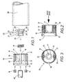
- FIGS. 1-3 shows a particularly advantageous embodiment of a connecting element according to the invention and areas of the subsequent, to be connected handrail or transition elements in a clear exploded view.
- the actual connecting element consists of the retaining sleeve 10 and the counterpart 20.
- the reference numeral 30 denotes a tubular handrail element.
- the object of the connecting element according to the invention is to connect the first handrail element 30 with a second handrail or transition element, of which only parts of a threaded bolt 40 are shown. It is conceivable that the threaded bolt 40 is fixed in the second handrail or transition element by clamping or screwing devices of known type or otherwise. However, the threaded bolt 40 may also be part of a special transition element, for. B. be a ball joint element.
- the counterpart 20 Before mounting the handrail, the counterpart 20 is introduced into the receiving chamber 11 of the retaining sleeve 10. The determination takes place via the rear portion 23 of the counterpart 20.
- a press fit 27 is provided for this purpose.
- a flange 28 defines the insertion depth into the receiving chamber 11.
- the front portion 24 of the counterpart 20 has a slightly smaller diameter, so that there is no direct attachment to the support sleeve 10.
- the counterpart 20 is penetrated by a through hole, which has an internal thread 24 in the front region 21.
- the thread 24 is adapted to the thread of the threaded bolt 40. If the counterpart 20 is fixed in the receiving chamber 11 of the holding bush 10, the entire insert can be introduced into the tubular handrail element 30.
- a flange 15 preferably defines a defined insertion depth.
- the determination of the insert 10/20 in the tube 30 is carried out in the embodiment shown by jamming. For this purpose, radially outward and axially rearward expansion slots 12 are provided in the retaining sleeve 10.
- the adjacent handrail or transition element is connected by its threaded bolt 40 inserted through the through hole 16 in the receiving chamber 11 of the retaining sleeve 10 and screwed into the thread 24 in the front portion 21 of the counterpart 20 becomes.
- the diameter of the thread 24 and the connecting hole 25 are chosen so that the purely positive connection of the thread 24 and 40 merges into a frictional connection.
- the threaded bolt is then screwed tight. Further action of torsional forces leads to the intended breakage of the counterpart 20 in the region 22, in particular at the predetermined breaking surface 26.
- the connected handrail elements are thus rotationally movable against each other.
- a relative axial mobility of the connected handrail elements is not possible because the diameter of the through hole 16, which limits the receiving chamber 11 of the retaining sleeve 10 forward, is smaller than the diameter of the front portion 21 of the counterpart 20. Only a very small, by manufacturing tolerances conditional, axial mobility is still present. At the in Fig. 1 shown embodiment, this residual mobility is reliably prevented by the use of the compensating spring 19, which pulls the connected elements within the tolerances in each other.
- Handrails connected in this way can be adapted as desired to the angles of individual building structures without their safety being compromised.
- the predetermined breaking region 22 of the counterpart 20 is realized in the embodiment shown by a region of reduced material thickness, which defines an exact, annular predetermined breaking surface.
- any other measure locally weakening the material in a defined manner is equally applicable.
- a ring of holes could be provided.
- the determination of the retaining sleeve 10 in the tube 30 must not be made in the manner explained by jamming.
- a screw or locking connection is also conceivable.
- the thread is preferably oriented in the same direction as the threaded bolt 40. The disadvantage here, however, is the more complex production of the tubes 30, would have to be cut into the internal thread.
- the front end face of the retaining bush is provided with a socket-like recess 17. This is particularly advantageous when spherical transition or end pieces to be connected with its threaded bolt 40 to the pipe member 30.
- the threaded bolt 40 of the illustrated embodiment can be thought of as being reduced to a substantially cylindrical pin with side pins which engage in a female thread 24 reduced to less than a single thread like a bayonet catch. Also in this embodiment, the advantageous transition from form to adhesion can be made possible by known measures.
- the connecting elements according to the invention are suitable for the connection of any kind of at least partially tubular and non-media-carrying elements.
Landscapes
- Engineering & Computer Science (AREA)
- Architecture (AREA)
- Civil Engineering (AREA)
- Structural Engineering (AREA)
- Mutual Connection Of Rods And Tubes (AREA)
- Steps, Ramps, And Handrails (AREA)
Claims (10)
- Pièce de raccordement permettant le raccordement axial ou coudé d'un premier élément (30) tubulaire au moins dans sa zone terminale, avec un autre élément présentant un goujon fileté (40), tout deux étant notamment des pièces constitutives de mains courantes,
comprenant un insert (10/20) introductible dans la zone terminale du premier élément (30), insert dans lequel il est possible de visser le goujon fileté (40) de l'autre élément, l'insert (10/20) se laissant immobiliser dans la zone terminale du premier élément (30), à l'intérieur de celui-ci,
caractérisé en ce que
l'insert (10/20) est configuré au moins en deux parties, à savoir en une douille extérieure (10) de retenue avec une chambre réceptacle (11) intérieure, et dedans une pièce antagoniste (20) comportant une zone avant et une zone arrière (21, 23),
zones dont la zone avant (21) comporte un taraudage (24) servant recevoir le goujon fileté (40) et présente un diamètre extérieur dépassant le calibre de l'orifice avant (16) de la chambre réceptacle (11)
et dont la zone arrière (23) comporte des moyens (27) destinés à immobiliser la pièce antagoniste (20) contre la douille de retenue (10),
les deux zones (21, 23) étant reliées entre elles par une zone de transition (22) qui casse en cas d'application d'une force de torsion accrue. - Pièce de raccordement selon la revendication 1, caractérisée en ce qu'un alésage de raccordement (25) suit le taraudage (24), alésage dont le diamètre équivaut approximativement au diamètre du fond de filet.
- Pièce de raccordement selon l'une des revendications 1 et 2, caractérisée en ce que le goujon fileté (40) et le filetage correspondant (24) interagissent à la manière d'une fermeture à baïonnettes.
- Pièce de raccordement selon l'une des revendications 1 à 3, caractérisée en ce que la zone arrière (23) de la pièce antagoniste (20) présente une partie cylindrique (27) enfonçable par adhérence de forces dans un évidement correspondant de la douille de retenue (10).
- Pièce de raccordement selon l'une des revendications 1 à 3, caractérisée en ce que la zone arrière (23) de la pièce antagoniste (20) présente un filetage extérieur permettant d'immobiliser ladite pièce dans un taraudage correspondant de la douille de retenue (10), et en ce qu'elle est orientée en sens opposé au taraudage (24), recevant le goujon fileté (40), de la zone avant (21) de la pièce antagoniste (20).
- Pièce de raccordement selon l'une des revendications 1 à 5, caractérisée en ce que la zone de transition (22), cassant lorsque la contrainte en torsion augmente, présente une épaisseur de matière nettement plus faible que la zone avant (21) et la zone arrière (23) de la pièce antagoniste (20).
- Pièce de raccordement selon l'une des revendications 1 à 6, caractérisée en ce que la douille de retenue (10) présente, dans sa zone radiale extérieure et axiale arrière, des fentes (12) en forme de corde d'arc, fentes qu'il est possible d'expanser en vissant des vis, notamment des vis sans tête (14), dans les taraudages (13) qui ont été prévus dans les fentes (12).
- Pièce de raccordement selon l'une des revendications 1 à 7, caractérisée en ce que la douille de retenue (10) présente, contre sa surface frontale avant, un creux (17) du type de celui d'une poêle, destiné à recevoir une zone en forme de secteur sphérique de l'autre élément à relier.
- Pièce de raccordement selon l'une des revendications 1 à 8, caractérisée en ce que la pièce antagoniste (20) est maintenue par contrainte ressort contre la douille de retenue (10).
- Pièce de raccordement selon l'une des revendications 1 à 9, caractérisée en ce que la douille de retenue (10) présente, dans sa surface extérieure, une gorge (18) s'étendant dans le sens axial.
Applications Claiming Priority (3)
| Application Number | Priority Date | Filing Date | Title |
|---|---|---|---|
| DE20001350U DE20001350U1 (de) | 2000-01-27 | 2000-01-27 | Verbindungsstück für rohrartige Elemente, insbesondere Handläufe |
| DE20001350U | 2000-01-27 | ||
| PCT/EP2001/000805 WO2001055528A1 (fr) | 2000-01-27 | 2001-01-25 | Piece de raccordement pour elements tubulaires, notamment pour mains courantes |
Publications (2)
| Publication Number | Publication Date |
|---|---|
| EP1250501A1 EP1250501A1 (fr) | 2002-10-23 |
| EP1250501B1 true EP1250501B1 (fr) | 2008-09-10 |
Family
ID=7936423
Family Applications (1)
| Application Number | Title | Priority Date | Filing Date |
|---|---|---|---|
| EP01946916A Expired - Lifetime EP1250501B1 (fr) | 2000-01-27 | 2001-01-25 | Piece de raccordement pour elements tubulaires, notamment pour mains courantes |
Country Status (4)
| Country | Link |
|---|---|
| EP (1) | EP1250501B1 (fr) |
| AU (1) | AU2001228491A1 (fr) |
| DE (2) | DE20001350U1 (fr) |
| WO (1) | WO2001055528A1 (fr) |
Families Citing this family (1)
| Publication number | Priority date | Publication date | Assignee | Title |
|---|---|---|---|---|
| CN211850489U (zh) * | 2019-12-12 | 2020-11-03 | 东莞双成电子塑胶有限公司 | 一种栏杆接头 |
Family Cites Families (2)
| Publication number | Priority date | Publication date | Assignee | Title |
|---|---|---|---|---|
| US5772252A (en) * | 1995-06-16 | 1998-06-30 | Malani; Jugal K. | Pipe junction holder with a novel torque-limiting device |
| US5658017A (en) * | 1995-10-03 | 1997-08-19 | Chirehdast; Mehran | Tube nut torque limiting method and apparatus |
-
2000
- 2000-01-27 DE DE20001350U patent/DE20001350U1/de not_active Expired - Lifetime
-
2001
- 2001-01-25 WO PCT/EP2001/000805 patent/WO2001055528A1/fr not_active Ceased
- 2001-01-25 AU AU2001228491A patent/AU2001228491A1/en not_active Abandoned
- 2001-01-25 EP EP01946916A patent/EP1250501B1/fr not_active Expired - Lifetime
- 2001-01-25 DE DE50114308T patent/DE50114308D1/de not_active Expired - Lifetime
Also Published As
| Publication number | Publication date |
|---|---|
| DE20001350U1 (de) | 2000-04-20 |
| DE50114308D1 (de) | 2008-10-23 |
| EP1250501A1 (fr) | 2002-10-23 |
| AU2001228491A1 (en) | 2001-08-07 |
| WO2001055528A1 (fr) | 2001-08-02 |
Similar Documents
| Publication | Publication Date | Title |
|---|---|---|
| EP0458069B1 (fr) | Liaison transversale pour des barres profilées | |
| EP1856418B1 (fr) | Douille de serrage et liaison par serrage | |
| EP1343974B2 (fr) | Systeme de connexion pour profiles | |
| EP3033979B1 (fr) | Dispositif de fixation destine a la fixation d'un objet sanitaire | |
| EP0206327B1 (fr) | Dispositif de connexion d'éléments tubulaires | |
| DE4030978C2 (de) | Verbindungseinrichtung für Rohre | |
| EP0477713B1 (fr) | Dispositif pour fixer notamment une pièce de construction tubulaire à une paroi ou un élément similaire | |
| EP0477707B1 (fr) | Dispositif d'assemblage notamment pour d'une pièce de construction tubulaire | |
| EP0564889A1 (fr) | Dispositif de raccordement, notamment pour une pièce de construction tubulaire | |
| DE4210488A1 (de) | Verbindungseinrichtung für ein insbesondere rohrförmiges Bauteil | |
| EP1223274B1 (fr) | Douille pour la fixation d'une ferrure à un profilé creux | |
| EP0267161B1 (fr) | Dispositif de vissage | |
| EP1250501B1 (fr) | Piece de raccordement pour elements tubulaires, notamment pour mains courantes | |
| EP0864767B1 (fr) | Manchon de raccord et dispositif pour la fixation d'objets à des murs ou similaires | |
| DE10109660B4 (de) | Sicherungsring und Befestigungsvorrichtung für eine Welle-Nabe-Verbindung | |
| EP1710452B1 (fr) | Système | |
| DE3147092C2 (de) | Verbindungssystem mit wenigstens einem Eckbogenelement | |
| DE3016224A1 (de) | Loesbares rohrgestell | |
| DE19912068A1 (de) | Wellen- oder Stellmutter und Verfahren zu ihrer Herstellung | |
| EP0382081B1 (fr) | Boulon pour connecter des pièces de construction à des surfaces murales | |
| DE10000226A1 (de) | Montagehülse | |
| EP0592843B1 (fr) | Ferrure, en particulier pour la connexion de plaques | |
| DE9114220U1 (de) | Bolzen zum Verbinden zweier Bauteile | |
| DE10008297B4 (de) | Fahrzeug | |
| DE19532456C2 (de) | Verbinder für Holzteile |
Legal Events
| Date | Code | Title | Description |
|---|---|---|---|
| PUAI | Public reference made under article 153(3) epc to a published international application that has entered the european phase |
Free format text: ORIGINAL CODE: 0009012 |
|
| 17P | Request for examination filed |
Effective date: 20020629 |
|
| AK | Designated contracting states |
Kind code of ref document: A1 Designated state(s): AT BE CH CY DE DK ES FI FR GB GR IE IT LI LU MC NL PT SE TR |
|
| AX | Request for extension of the european patent |
Free format text: AL;LT;LV;MK;RO;SI |
|
| RAP1 | Party data changed (applicant data changed or rights of an application transferred) |
Owner name: AUGUST VORMANN GMBH & CO. |
|
| RBV | Designated contracting states (corrected) |
Designated state(s): DE ES FR GB NL |
|
| GRAP | Despatch of communication of intention to grant a patent |
Free format text: ORIGINAL CODE: EPIDOSNIGR1 |
|
| GRAS | Grant fee paid |
Free format text: ORIGINAL CODE: EPIDOSNIGR3 |
|
| GRAA | (expected) grant |
Free format text: ORIGINAL CODE: 0009210 |
|
| AK | Designated contracting states |
Kind code of ref document: B1 Designated state(s): DE ES FR GB NL |
|
| REG | Reference to a national code |
Ref country code: GB Ref legal event code: FG4D Free format text: NOT ENGLISH |
|
| REF | Corresponds to: |
Ref document number: 50114308 Country of ref document: DE Date of ref document: 20081023 Kind code of ref document: P |
|
| NLV1 | Nl: lapsed or annulled due to failure to fulfill the requirements of art. 29p and 29m of the patents act | ||
| PG25 | Lapsed in a contracting state [announced via postgrant information from national office to epo] |
Ref country code: ES Free format text: LAPSE BECAUSE OF FAILURE TO SUBMIT A TRANSLATION OF THE DESCRIPTION OR TO PAY THE FEE WITHIN THE PRESCRIBED TIME-LIMIT Effective date: 20081221 |
|
| PG25 | Lapsed in a contracting state [announced via postgrant information from national office to epo] |
Ref country code: NL Free format text: LAPSE BECAUSE OF FAILURE TO SUBMIT A TRANSLATION OF THE DESCRIPTION OR TO PAY THE FEE WITHIN THE PRESCRIBED TIME-LIMIT Effective date: 20080910 |
|
| PLBE | No opposition filed within time limit |
Free format text: ORIGINAL CODE: 0009261 |
|
| STAA | Information on the status of an ep patent application or granted ep patent |
Free format text: STATUS: NO OPPOSITION FILED WITHIN TIME LIMIT |
|
| 26N | No opposition filed |
Effective date: 20090611 |
|
| GBPC | Gb: european patent ceased through non-payment of renewal fee |
Effective date: 20090125 |
|
| REG | Reference to a national code |
Ref country code: FR Ref legal event code: ST Effective date: 20091030 |
|
| PG25 | Lapsed in a contracting state [announced via postgrant information from national office to epo] |
Ref country code: GB Free format text: LAPSE BECAUSE OF NON-PAYMENT OF DUE FEES Effective date: 20090125 |
|
| PG25 | Lapsed in a contracting state [announced via postgrant information from national office to epo] |
Ref country code: FR Free format text: LAPSE BECAUSE OF NON-PAYMENT OF DUE FEES Effective date: 20090202 |
|
| PGFP | Annual fee paid to national office [announced via postgrant information from national office to epo] |
Ref country code: DE Payment date: 20150106 Year of fee payment: 15 |
|
| REG | Reference to a national code |
Ref country code: DE Ref legal event code: R119 Ref document number: 50114308 Country of ref document: DE |
|
| PG25 | Lapsed in a contracting state [announced via postgrant information from national office to epo] |
Ref country code: DE Free format text: LAPSE BECAUSE OF NON-PAYMENT OF DUE FEES Effective date: 20160802 |