EP1250873A2 - Aufhänger - Google Patents
Aufhänger Download PDFInfo
- Publication number
- EP1250873A2 EP1250873A2 EP02008175A EP02008175A EP1250873A2 EP 1250873 A2 EP1250873 A2 EP 1250873A2 EP 02008175 A EP02008175 A EP 02008175A EP 02008175 A EP02008175 A EP 02008175A EP 1250873 A2 EP1250873 A2 EP 1250873A2
- Authority
- EP
- European Patent Office
- Prior art keywords
- hanger according
- holding body
- curtain
- guide element
- sleeve
- Prior art date
- Legal status (The legal status is an assumption and is not a legal conclusion. Google has not performed a legal analysis and makes no representation as to the accuracy of the status listed.)
- Granted
Links
- 238000006073 displacement reaction Methods 0.000 claims description 14
- 239000000463 material Substances 0.000 claims description 7
- 230000007704 transition Effects 0.000 claims description 6
- 239000004033 plastic Substances 0.000 claims description 5
- 230000002787 reinforcement Effects 0.000 claims description 3
- 210000002414 leg Anatomy 0.000 description 18
- 238000003780 insertion Methods 0.000 description 6
- 230000037431 insertion Effects 0.000 description 6
- 238000000034 method Methods 0.000 description 4
- 210000000689 upper leg Anatomy 0.000 description 4
- 239000011324 bead Substances 0.000 description 3
- 238000004519 manufacturing process Methods 0.000 description 3
- 239000002184 metal Substances 0.000 description 3
- 239000004952 Polyamide Substances 0.000 description 1
- 238000010521 absorption reaction Methods 0.000 description 1
- 210000000078 claw Anatomy 0.000 description 1
- 238000005553 drilling Methods 0.000 description 1
- 238000009434 installation Methods 0.000 description 1
- 238000005058 metal casting Methods 0.000 description 1
- 229920002647 polyamide Polymers 0.000 description 1
- 238000003466 welding Methods 0.000 description 1
Images


Classifications
-
- A—HUMAN NECESSITIES
- A47—FURNITURE; DOMESTIC ARTICLES OR APPLIANCES; COFFEE MILLS; SPICE MILLS; SUCTION CLEANERS IN GENERAL
- A47H—FURNISHINGS FOR WINDOWS OR DOORS
- A47H13/00—Fastening curtains on curtain rods or rails
- A47H13/01—Fastening curtains on curtain rods or rails by clamps; by clamps attached to hooks or rings
-
- A—HUMAN NECESSITIES
- A47—FURNITURE; DOMESTIC ARTICLES OR APPLIANCES; COFFEE MILLS; SPICE MILLS; SUCTION CLEANERS IN GENERAL
- A47H—FURNISHINGS FOR WINDOWS OR DOORS
- A47H15/00—Runners or gliders for supporting curtains on rails or rods
Definitions
- the invention relates to a hanger for the movable arrangement of a Curtain, a curtain or tarpaulin on a guide rail, with a Guide element and with a holding body, which fasteners for the Has a curtain, curtain or tarpaulin.
- EP 1 080 675 A1 discloses a hanger with a hook for hanging in a guide element and with a holding body.
- the holding body has two hinged and one fold of the curtain encompassing thighs.
- a separate fastening clip is used for clamping the thigh.
- the hanger has a complicated structure and requires an elaborate tool. Due to the hook, the holding body cannot be held captive on a guide element.
- US 5 388 313 discloses a two-part hanger, one Holding body for the detachable fastening of a flat material and a has pivotally connected fastening loop on which the Hanger is hung together with the flat material.
- the Fastening loop and the holding body are after assembly inextricably linked.
- the hanger uses curtains, tarpaulins or curtains with high Weight, e.g. for use with car and advertising tarpaulins, tents, stage or industrial curtains.
- the guide element releasably on the holding body is attachable.
- the overall function of the Hanger namely holding a curtain or the like, in two Sub-functions separately, namely the attachment of the curtain, etc. on the Hanger itself and the guidance of the hanger on a guide rail or similar.
- the latter function, performed by the guide element of the Hanger running, can be customized to the used Guide rail or the like.
- That the guide element is releasably and thus interchangeably attached to the holding body.
- a curtain or the like on a tether Guide elements on the hanger are used, for example, in the Use of a guide rail. In this way it is not only possible to use the same bracket for curtains on different curtains Guide rails or the like. To be attached, but it is also possible the guide elements, which are subject to a certain amount of wear, easy to replace.
- a particularly simple and inexpensive detachable fastening of Guide element and holding body can be achieved by locking or clamping means become.
- this Guide element has a T-shaped end with a cross bar for engaging in one End of the holding body. In this way, the guide element is safe fixed in the holding body, so that even large loads through this Connection are transferable.
- the inclusion of the guide element in the holding body is thereby relieved that the side of the crossbar facing away from the holding body to the Outer edges are chamfered or rounded.
- T-shaped configuration of the guide element possible to provide locking pins on the guide element. These are suitable especially for absorbing large forces such. B. when hanging from Stage curtains or large and heavy tarpaulins.
- the holding body is advantageously provided with a latching recess and with a Provide groove for engagement of the locking or clamping means. This will make one simple but secure releasable attachment of the guide element to the Holding body allows.
- the holding body has a encompassing the guide element at least in some areas Fastening area.
- the guide element is so in the Fastening area of the holding body added that an unwanted Falling out of the guide element can be avoided.
- the Fastening area parallel to a displacement axis of the curtain or the like lying sleeve which has at least one in their Circumferential direction first slot and at least one in their Axial direction extending second slot having each other in Connect.
- One embodiment is particularly preferred which is the first slot over a range of 90 ° to 210 ° of the sleeve extends and the second slot does not extend the full length of the sleeve extends.
- a guide element for example a T-shaped end or Has locking pin, can in this embodiment of the mounting area of the holding body through the axial slot in the sleeve and by pivoting the guide element about the axis of the sleeve in brought into position in the circumferential direction of the first slot in which the guide element is held securely in the sleeve.
- the Replacing a guide element is thus in no time and with lowest possible technical effort possible.
- the at their ends reinforced sleeve absorb large forces.
- the guide element in the sleeve in snap into an installation position that prevents unintended pivoting of the Guide element in the sleeve and thus the possibility of falling out of the guide element from the sleeve additionally difficult.
- the guide element for sliding in a guide rail a sliding body or in pairs has rollers mounted on an axle.
- the number of sliders or Rollers and axles can be multiplied if very heavy tarpaulins are used.
- a particularly even and centric load on the guide rail and the guide element is present when the holding body two Has leg, which is a part of the curtain, the curtain or the tarpaulin spread.
- the legs are preferably parallel to the Axis of displacement of the curtain, curtain or tarpaulin arranged. This allows the curtain to be attached to the hanger without any creases. At the same time, due to the symmetrical design, misalignments are avoided assembly avoided.
- Manufacturing and assembly can be further simplified in that the Legs are arranged in one piece on the holding body.
- One between the Legs provided receiving groove can position a upper edge of the curtain in the space between the legs enable.
- the inside of the legs has a surface structure, in particular with teeth or corrugation are provided by the pressure and Claw a reliable fastening of the curtain or the like.
- the legs with the curtain the curtain or Tarpaulin screwed, riveted, glued, welded or sewn.
- hanger and the tarpaulin are made of plastic, one can inexpensive attachment using a hot air, hot wedge, high frequency or ultrasonic welding process. Self-lubricating Properties of the plastic facilitate the lateral displacement of the Guide elements in the guide rail.
- a hanger 1 for the movable arrangement of a curtain, not shown, a curtain or tarpaulin on a guide rail, not shown, or the like. has a guide element 2 and a guide rail side Holding body 3 with attachable attachments 4.
- a Direction of extension of a displacement axis A of the guide rail each exemplified in Figures 1b, 6b, 15 and 19b.
- the Holding body 3 has two legs 5, 6, which have an upper, ceiling part of the curtain, curtain or tarpaulin - preferably overlap an edge - U-shaped.
- the design of the hanger 1 results in a central introduction of the Curtain weight in the guide rail or the like. And thereby one centric stress on the guide element 2.
- the two legs 5, 6 extend parallel to each other and parallel to the axis of displacement A. the guide rail or the like. and are integral with the holding body 3 arranged.
- the holding body 3 does not have a center to the shown guide rail provided mounting area 7 for releasable Connection of the holding body 3 with the guide element 2.
- the Holding body 3 via a branch point 8, from which the two legs 5, 6 out.
- There is one between each leg 5, 6 Receiving groove 9, into which the curtain, curtain or tarpaulin is threaded can be.
- the groove points depending on the thickness of the curtain or the tarpaulin, for example, has a width of 1 mm.
- the fastening area 7 of the holding body 3 is in the direction of the Displacement axis A extending sleeve 15 formed which is integral with the holding body 3 is formed.
- the sleeve 15 has at least a first one Slot 16 which extends in the circumferential direction of the sleeve.
- the first slot 16 extends over a range of approximately 90 ° to 210 ° of the sleeve in which enlarged representation of Figures 5a to 5c about half the circumference (180 °) of the sleeve 15.
- the second slot 17 essentially opens at right angles in the first slot 16, so that the two slots 16, 17 a define approximately T-shaped opening in the sleeve 15, which with the is enclosed by the sleeve 15 cavity.
- On the Cavity facing inside of the sleeve 15 are a plurality of projections 18th formed so that the cavity enclosed by the sleeve 15, as in the Figures 5a to 5c shown a substantially cross-shaped cross section having.
- a further slot 19 which extends over the entire length of the Holding body 3 extends and substantially parallel to the Displacement axis A runs.
- the holding body 3 also has a through hole or opening 20 for passing a pull rope.
- Each through hole 20 extends parallel to the axis of displacement A, so that the pull rope through the Holding body 3 can be passed through, and on an end hanger 1 is attachable.
- One opening at right angles into the through hole 20 Hole 21 is used to screw in a fastener (screw) Securing the position of the hanger 1 relative to the pull rope.
- the guide element 2 points in that shown in Figures 1a to 13 Embodiments with a lower T-shaped end 22 in the figures a crossbar 23 on.
- the crosspiece 23 extends essentially parallel to the axis of displacement A of the hanger 1.
- the holding body 3 facing outer edges of the crosspiece 23 can be chamfered or as in the Figures are shown rounded.
- Material reinforcements 24 in the area of the transition into the guide element 2 be designed to increase the strength in this transition region.
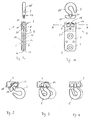
- FIGS. 1a to 6b Guide element 2 equipped with a hook-shaped ring holder 25. Further embodiments of the guide element 2 are shown in FIGS. 7 mapped to 13. 7 shows a ring hook 26, FIG. 8 an open one Rope holder 27, FIG. 9 a closed rope holder 28, FIG. 10 a cranked piping hook 29, Figure 11 with a two-axis roll holder 30 two axes 31a, 31b, not shown on each side of the hanger Can carry rollers, Figure 12 shows a uniaxial roller holder 32 and Figure 13 shows a guide element 2 with ball hook 33.
- FIGS. 1a to 6b show as an example with a ring holder 25.
- Fig. 2 shows how now first end of the crossbar 23 in the second, extending in the axial direction extending slot 17 of the holding body 3 is inserted.
- the length of the second slot 17 is smaller in the exemplary embodiments shown than the length of the crossbar 23.
- FIG. 14 shows a further embodiment of a holding body 3, which is different from differs from the embodiment shown in FIGS. 1a to 6b in that that only one fastening means 4 is provided on the holding body 3.
- the holding body 3 shown in FIG. 14 is therefore particularly suitable for the Use with light curtains or curtains.
- Figure 15 shows a holding body 3, which is used for the attachment of heavy tarpaulins or curtains.
- the Holding body 3 has two first slots 16a and 16b and two second slots 17a and 17b.
- Examples of guide elements 2, which on the Holding bodies 3 shown in FIG. 15 can be fastened are shown in FIGS. 16a to 18 shown.
- Figures 16a and 16b show different ones Views a ring holder 34 while in Figures 17 and 18 biaxial roll holder 30 and a uniaxial roll holder 32 shown are.
- FIGS. 19a to 19c Embodiment of a holding body 3 are each other in the direction of the axis of displacement A. opposite ends of the sleeve 15 each by a bead 36a or 36b completed. In this way it is possible for greater forces to go through the sleeve 15 reinforced by the bead 36 are received.
- This Embodiment is therefore particularly suitable for extremely heavy curtains or tarpaulins, such as stage curtains or so-called side curtain tarpaulins for trucks.
- FIGS. 19b and 19c there is also a narrowing 37 caused by the two slots 16, 17 defined opening in the sleeve 15.
- the guide element 2 is thus triple in the holding body 3 Secured falling out: first over the longer one compared to slot 17 Cross bar 23, further over the projections 18 and finally also over the Cross-sectional narrowing 37.
- the cross bar 23 of the same length how to form the slot 17.
- the insertion or insertion of the Crossbar 23 in the sleeve 15 according to Figures 2 to 4 can be omitted. Due to the shorter length of the crossbar 23, however, this can only lower forces are transmitted from the guide element 2 to the holding body 3 become.
- Locking pin 35 is used to compensate for the reduced force absorption shortened locking pin 35 possible, not only, as in Figures 16 to 18 shown to provide outwardly facing locking pins 35a, 35b, but to form additional locking pins pointing inwards.
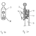
- a positioning hole 38 is provided on one or both Legs 5, 6 between the holes 21 for riveting or screwing a positioning hole 38 is provided.
- the insertion tool (rivet plate) 39 shown is then between rivet dies 40 Threaded or retaining pin 41 is provided. If the set screw 41 is unscrewed, the holding body 3 with the positioning hole 38 can thus enter the tool 39 are inserted that the holding body 3 firmly and securely in the tool 39 lies and does not slip when the tarpaulin material or the like is inserted. at overhead handling is also possible for this handling, since the holding body 3 cannot fall out of the tool 39.
- the pin 41 also secures the situation of the holding body 3 when riveting against unintentional shifting.
- Holding bodies 3 without a positioning hole can be used with the insertion tool 39 withdrawn set screw 41 can also be used. 21 are shown in the bores 21 pre-assembled rivets 42, through which the assembly can also be simplified.
- the guide elements 2 and the holding bodies 3 are preferably made of Plastic, for example polyamide or PVC. However, it is also possible the guide elements 2 and / or the holding body 3 made of metal, for example to manufacture as metal castings or metal stampings.
Landscapes
- Curtains And Furnishings For Windows Or Doors (AREA)
- Holders For Apparel And Elements Relating To Apparel (AREA)
Abstract
Description
- Fig. 1a bis 6b
- teilweise ausschnittsweise einen Aufhänger gemäß einer ersten Ausführungsform der Erfindung in verschiedenen Stadien des Befestigens des Führungselements an dem Haltekörper,
- Fig. 7 bis 13
- erfindungsgemäße Ausführungsformen von Führungs-elementen,
- Fig. 14 und 15
- verschiedene Ausführungsformen von Haltekörpern,
- Fig. 16a bis 18
- weitere Ausführungsformen von Führungselementen,
- Fig. 19a bis 19c
- verschiedene Ansichten eines Haltekörpers nach einer weiteren Ausführungsform der Erfindung,
- Fig. 20
- eine Draufsicht auf einen Aufhänger gemäß einer weiteren Ausführungsform der Erfindung und
- Fig. 21
- die Anordnung des Aufhängers gemäß Fig. 20 an einem Einsetzwerkzeug im Teilschnitt.
- 1
- Aufhänger
- 2
- Führungselement
- 3
- Haltekörper
- 4
- Befestigungsmittel
- 5
- Schenkel
- 6
- Schenkel
- 7
- Befestigungsbereich
- 8
- Abzweigstelle
- 9
- Aufnahmenut
- 10
- Schenkelinnenseite
- 11
- Schenkelinnenseite
- 12
- Struktur
- 13
- Vorsprung
- 14
- Ausnehmung
- 15
- Hülse
- 16
- erster Schlitz
- 17
- zweiter Schlitz
- 18
- Vorsprung
- 19
- weiterer Schlitz
- 20
- Durchgangsbohrung
- 21
- Bohrung
- 22
- T-förmiges Ende
- 23
- Quersteg
- 24
- Materialverstärkung
- 25
- Ringhalter
- 26
- Ringhaken
- 27
- offener Seilhalter
- 28
- geschlossener Seilhalter
- 29
- gekröpfter Kederhaken
- 30
- zweiachsiger Rollenhalter
- 31
- Achse
- 32
- einachsiger Rollenhalter
- 33
- Kugelhaken
- 34
- Ringhalter
- 35
- Rastzapfen
- 36
- Wulst
- 37
- Querschnittsverengung
- 38
- Positionierungsloch
- 39
- Einsetzwerkzeug
- 40
- Nietdöpper
- 41
- Stift
- 42
- Niet
- A
- Verschiebungsachse
Claims (22)
- Aufhänger zur bewegbaren Anordnung eines Vorhanges, einer Gardine oder Plane an einer Führungsschiene oder dgl., mit einem Führungselement (2) und mit einem Haltekörper (3), welcher Befestigungsmittel (4) für den Vorhang, Gardine oder Plane aufweist, dadurch gekennzeichnet, dass das Führungselement (2) lösbar an dem Haltekörper (3) befestigbar ist.
- Aufhänger nach Anspruch 1, dadurch gekennzeichnet, dass das Führungselement (2) und der Haltekörper (3) mit Rast- oder Klemmmitteln (23; 35) zur lösbaren Befestigung versehen sind.
- Aufhänger nach einem der vorhergehenden Ansprüche, dadurch gekennzeichnet, dass das Führungselement (2) ein T-förmiges Ende (22) mit einem Quersteg (23) zum Eingriff in ein Ende des Haltekörpers (3) aufweist.
- Aufhänger nach Anspruch 3, dadurch gekennzeichnet, dass die dem Haltekörper (3) abgewandte Seite des Querstegs (23) an den Außenkanten angefast oder abgerundet ist.
- Aufhänger nach Anspruch 3 oder 4, dadurch gekennzeichnet, dass an jeder Seite des Querstegs (23) Materialverstärkungen (24) im Bereich des Übergangs in das Führungselement (2) ausgebildet sind.
- Aufhänger nach einem der Ansprüche 1 oder 2, dadurch gekennzeichnet, dass das Führungselement (2) Rastzapfen (35) aufweist.
- Aufhänger nach einem der vorhergehenden Ansprüche, dadurch gekennzeichnet, dass der Haltekörper (3) mit einer Rastausnehmung und mit einer Nut (16, 17) zum Eingriff der Rast- oder Klemmmittel (23; 35) versehen ist.
- Aufhänger nach einem der Ansprüche 1 bis 6, dadurch gekennzeichnet, dass der Haltekörper (3) einen das Führungselement (2) zumindest bereichsweise umgreifenden Befestigungsbereich (7) aufweist.
- Aufhänger nach Anspruch 8, dadurch gekennzeichnet, dass der Befestigungsbereich (7) eine parallel zu einer Verschiebungsachse (A) des Vorhanges oder dgl. liegende Hülse (15) umfasst, die wenigstens einen in deren Umfangsrichtung verlaufenden ersten Schlitz (16) und wenigstens einen in deren axialer Richtung verlaufenden zweiten Schlitz (17) aufweist, die miteinander in Verbindung stehen.
- Aufhänger nach Anspruch 9, dadurch gekennzeichnet, dass der erste Schlitz (16) sich über einen Bereich von 90° bis 210° der Hülse (15), vorzugsweise ca. 180° erstreckt.
- Aufhänger nach einem der Ansprüche 9 oder 10, dadurch gekennzeichnet, dass sich der zweite Schlitz (17) nicht über die volle Länge der Hülse (15) erstreckt.
- Aufhänger nach einem der Ansprüche 9 bis 11, dadurch gekennzeichnet, dass in dem Übergangsbereich zwischen dem ersten und dem zweiten Schlitz (16, 17) eine Verengung (37) der durch die Schlitze (16, 17) definierten Öffnung in der Hülse (15) vorgesehen ist.
- Aufhänger nach einem der Ansprüche 8 bis 12, dadurch gekennzeichnet, dass die Innenkontur des Befestigungsbereichs (7) wenigstens einen Vorsprung (18) aufweist.
- Aufhänger nach einem der Ansprüche 8 bis 13, dadurch gekennzeichnet, dass die Hülse (15) einen weiteren, sich über ihre gesamte Länge erstreckenden Schlitz (19) aufweist.
- Aufhänger nach einem der vorhergehenden Ansprüche, dadurch gekennzeichnet, dass das Führungselement (2) einen Gleitkörper (29; 33) oder paarweise auf einer Achse (31) gelagerte Laufrollen aufweist.
- Aufhänger nach einem der Ansprüche 1 bis 14, dadurch gekennzeichnet, dass das Führungselement (2) einen Haken (27), einen Ringhalter (25) oder eine Öse (28; 26) aufweist.
- Aufhänger nach einem der vorhergehenden Ansprüche, dadurch gekennzeichnet, dass der Haltekörper (3) zwei Schenkel (5, 6) aufweist, welche einen Teil des Vorhanges, der Gardine oder der Plane übergreifen.
- Aufhänger nach Anspruch 17, dadurch gekennzeichnet, dass die Schenkel (5, 6) parallel zueinander sowie parallel zu der Verschiebungsachse (A) des Vorhangs, der Gardine oder Plane angeordnet sind.
- Aufhänger nach Anspruch 17 oder 18, dadurch gekennzeichnet, dass die Schenkel (5, 6) einstückig an dem Haltekörper (3) angeordnet sind und dass zwischen den Schenkeln (5, 6) eine Aufnahmenut (9) vorgesehen ist.
- Aufhänger nach einem der Ansprüche 17 bis 19, dadurch gekennzeichnet, dass Schenkelinnenseiten (10, 11) der Schenkel (5, 6) mit einer Struktur (12), insbesondere einer Zahnung (13, 14) oder Riffelung versehen sind.
- Aufhänger nach einem der Ansprüche 17 bis 20, dadurch gekennzeichnet, dass die Schenkel (5, 6) mit dem Vorhang, mit der Gardine, oder mit der Plane verschraubt, vernietet, verklebt, verschweißt, verklemmt oder vernäht sind.
- Aufhänger nach einem der vorhergehenden Ansprüche, dadurch gekennzeichnet, dass er aus Kunststoff besteht.
Applications Claiming Priority (4)
| Application Number | Priority Date | Filing Date | Title |
|---|---|---|---|
| DE20106827U | 2001-04-19 | ||
| DE20106827 | 2001-04-19 | ||
| DE20119464U | 2001-11-29 | ||
| DE20119464U DE20119464U1 (de) | 2001-04-19 | 2001-11-29 | Aufhänger |
Publications (3)
| Publication Number | Publication Date |
|---|---|
| EP1250873A2 true EP1250873A2 (de) | 2002-10-23 |
| EP1250873A3 EP1250873A3 (de) | 2004-02-04 |
| EP1250873B1 EP1250873B1 (de) | 2010-06-09 |
Family
ID=26056940
Family Applications (1)
| Application Number | Title | Priority Date | Filing Date |
|---|---|---|---|
| EP20020008175 Expired - Lifetime EP1250873B1 (de) | 2001-04-19 | 2002-04-16 | Aufhänger |
Country Status (1)
| Country | Link |
|---|---|
| EP (1) | EP1250873B1 (de) |
Cited By (1)
| Publication number | Priority date | Publication date | Assignee | Title |
|---|---|---|---|---|
| CN100340453C (zh) * | 2004-07-09 | 2007-10-03 | 中国国际海运集装箱(集团)股份有限公司 | 登机桥接机口遮篷装置及遮蓬篷布和遮篷骨架的连接方法 |
Citations (1)
| Publication number | Priority date | Publication date | Assignee | Title |
|---|---|---|---|---|
| US4125143A (en) | 1974-11-12 | 1978-11-14 | Gardisette Holding Ag | Curtain or drapery hanging arrangement |
Family Cites Families (1)
| Publication number | Priority date | Publication date | Assignee | Title |
|---|---|---|---|---|
| US3626429A (en) * | 1969-10-29 | 1971-12-07 | Ellis I Toder | Detachable drapery carrier |
-
2002
- 2002-04-16 EP EP20020008175 patent/EP1250873B1/de not_active Expired - Lifetime
Patent Citations (1)
| Publication number | Priority date | Publication date | Assignee | Title |
|---|---|---|---|---|
| US4125143A (en) | 1974-11-12 | 1978-11-14 | Gardisette Holding Ag | Curtain or drapery hanging arrangement |
Cited By (1)
| Publication number | Priority date | Publication date | Assignee | Title |
|---|---|---|---|---|
| CN100340453C (zh) * | 2004-07-09 | 2007-10-03 | 中国国际海运集装箱(集团)股份有限公司 | 登机桥接机口遮篷装置及遮蓬篷布和遮篷骨架的连接方法 |
Also Published As
| Publication number | Publication date |
|---|---|
| EP1250873B1 (de) | 2010-06-09 |
| EP1250873A3 (de) | 2004-02-04 |
Similar Documents
| Publication | Publication Date | Title |
|---|---|---|
| EP3685057B1 (de) | Verbinder mit fixierelement für anbauteil | |
| DE3843096C2 (de) | Befestigungseinrichtung für Verkleidungen | |
| DE8120936U1 (de) | Rohrfensterheber, insbesondere fuer kraftfahrzeugfenster | |
| EP1810852B1 (de) | Balg eines Übergangs zwischen zwei gelenkig miteinander verbundenen Fahrzeugen | |
| DE19829332B4 (de) | Gurthalter | |
| DE19823075C2 (de) | Verschluß zum Verbinden der beiden freien, jeweils mit einer Verdickung versehenen Enden eines Bügelstranges der Seitenhalterung einer Gleitschutzkette | |
| EP1250873B1 (de) | Aufhänger | |
| DE60210236T2 (de) | Seilklemme und gepäckhaltevorrichtung | |
| DE202017105765U1 (de) | Befestigungsvorrichtung zur Befestigung von mindestens einem Bauteil | |
| DE2201812B2 (de) | Anhängevorrichtung des Schaftzuges am Webschaftrahmen | |
| EP4332388A1 (de) | Vorrichtung zum ausgleichen von toleranzen | |
| EP1250872A2 (de) | Aufhänger | |
| WO2024170400A1 (de) | Anhängekupplung mit einer ösenanordnung | |
| DE20119464U1 (de) | Aufhänger | |
| DE3137769C2 (de) | Vorhangzugeinrichtung mit Vorläufer | |
| DE3619673C2 (de) | ||
| DE3416814C2 (de) | ||
| EP0917971A2 (de) | Seitenhalterung für eine Gleitschutzkette | |
| DE20218023U1 (de) | Vorrichtung zum Sichern von Ladegut auf der Ladefläche eines Fahrzeuges | |
| DE102015105142B4 (de) | Seilzugeinstellung | |
| DE102013011527A1 (de) | Befestigungsanordnung | |
| EP0989310A2 (de) | Schnellverstellmutter | |
| DE29815824U1 (de) | Arretierelement zur lösbaren Arretierung einer Verbindung, insbesondere zweier rohrförmiger Bauteile eines Kinderfahrzeugs | |
| DE2612426C2 (de) | Kegelförmige Fangprofile für Kupplungsbolzen an landwirtschaftlichen Geräten | |
| DE102015109172A1 (de) | Nutzfahrzeugaufbau mit einer Plane, Nutzfahrzeug mit einem derartigen Nutzfahrzeugaufbau und Verfahren zur Herstellung eines Nutzfahrzeugaufbaus |
Legal Events
| Date | Code | Title | Description |
|---|---|---|---|
| PUAI | Public reference made under article 153(3) epc to a published international application that has entered the european phase |
Free format text: ORIGINAL CODE: 0009012 |
|
| AK | Designated contracting states |
Kind code of ref document: A2 Designated state(s): AT BE CH CY DE DK ES FI FR GB GR IE IT LI LU MC NL PT SE TR |
|
| AX | Request for extension of the european patent |
Free format text: AL;LT;LV;MK;RO;SI |
|
| RIC1 | Information provided on ipc code assigned before grant |
Ipc: 7A 47H 15/00 B Ipc: 7A 47H 15/04 A |
|
| PUAL | Search report despatched |
Free format text: ORIGINAL CODE: 0009013 |
|
| AK | Designated contracting states |
Kind code of ref document: A3 Designated state(s): AT BE CH CY DE DK ES FI FR GB GR IE IT LI LU MC NL PT SE TR |
|
| AX | Request for extension of the european patent |
Extension state: AL LT LV MK RO SI |
|
| 17P | Request for examination filed |
Effective date: 20040624 |
|
| AKX | Designation fees paid |
Designated state(s): AT BE CH CY DE DK ES FI FR GB GR IE IT LI LU MC NL PT SE TR |
|
| AXX | Extension fees paid |
Extension state: AL Payment date: 20040624 Extension state: RO Payment date: 20040624 Extension state: SI Payment date: 20040624 Extension state: LT Payment date: 20040624 Extension state: MK Payment date: 20040624 Extension state: LV Payment date: 20040624 |
|
| 17Q | First examination report despatched |
Effective date: 20070319 |
|
| RAP1 | Party data changed (applicant data changed or rights of an application transferred) |
Owner name: MICHAEL MUELLER GRUNDBESITZ GMBH & CO. KG |
|
| GRAP | Despatch of communication of intention to grant a patent |
Free format text: ORIGINAL CODE: EPIDOSNIGR1 |
|
| GRAS | Grant fee paid |
Free format text: ORIGINAL CODE: EPIDOSNIGR3 |
|
| GRAA | (expected) grant |
Free format text: ORIGINAL CODE: 0009210 |
|
| AK | Designated contracting states |
Kind code of ref document: B1 Designated state(s): AT BE CH CY DE DK ES FI FR GB GR IE IT LI LU MC NL PT SE TR |
|
| AX | Request for extension of the european patent |
Extension state: AL LT LV MK RO SI |
|
| REG | Reference to a national code |
Ref country code: CH Ref legal event code: EP |
|
| REG | Reference to a national code |
Ref country code: IE Ref legal event code: FG4D Free format text: LANGUAGE OF EP DOCUMENT: GERMAN |
|
| REF | Corresponds to: |
Ref document number: 50214478 Country of ref document: DE Date of ref document: 20100722 Kind code of ref document: P |
|
| REG | Reference to a national code |
Ref country code: NL Ref legal event code: VDEP Effective date: 20100609 |
|
| PG25 | Lapsed in a contracting state [announced via postgrant information from national office to epo] |
Ref country code: SE Free format text: LAPSE BECAUSE OF FAILURE TO SUBMIT A TRANSLATION OF THE DESCRIPTION OR TO PAY THE FEE WITHIN THE PRESCRIBED TIME-LIMIT Effective date: 20100609 |
|
| LTIE | Lt: invalidation of european patent or patent extension |
Effective date: 20100609 |
|
| PG25 | Lapsed in a contracting state [announced via postgrant information from national office to epo] |
Ref country code: FI Free format text: LAPSE BECAUSE OF FAILURE TO SUBMIT A TRANSLATION OF THE DESCRIPTION OR TO PAY THE FEE WITHIN THE PRESCRIBED TIME-LIMIT Effective date: 20100609 |
|
| PG25 | Lapsed in a contracting state [announced via postgrant information from national office to epo] |
Ref country code: GR Free format text: LAPSE BECAUSE OF FAILURE TO SUBMIT A TRANSLATION OF THE DESCRIPTION OR TO PAY THE FEE WITHIN THE PRESCRIBED TIME-LIMIT Effective date: 20100910 Ref country code: CY Free format text: LAPSE BECAUSE OF FAILURE TO SUBMIT A TRANSLATION OF THE DESCRIPTION OR TO PAY THE FEE WITHIN THE PRESCRIBED TIME-LIMIT Effective date: 20100609 |
|
| REG | Reference to a national code |
Ref country code: IE Ref legal event code: FD4D |
|
| PG25 | Lapsed in a contracting state [announced via postgrant information from national office to epo] |
Ref country code: IE Free format text: LAPSE BECAUSE OF FAILURE TO SUBMIT A TRANSLATION OF THE DESCRIPTION OR TO PAY THE FEE WITHIN THE PRESCRIBED TIME-LIMIT Effective date: 20100609 Ref country code: NL Free format text: LAPSE BECAUSE OF FAILURE TO SUBMIT A TRANSLATION OF THE DESCRIPTION OR TO PAY THE FEE WITHIN THE PRESCRIBED TIME-LIMIT Effective date: 20100609 |
|
| PG25 | Lapsed in a contracting state [announced via postgrant information from national office to epo] |
Ref country code: PT Free format text: LAPSE BECAUSE OF FAILURE TO SUBMIT A TRANSLATION OF THE DESCRIPTION OR TO PAY THE FEE WITHIN THE PRESCRIBED TIME-LIMIT Effective date: 20101011 |
|
| PLBE | No opposition filed within time limit |
Free format text: ORIGINAL CODE: 0009261 |
|
| STAA | Information on the status of an ep patent application or granted ep patent |
Free format text: STATUS: NO OPPOSITION FILED WITHIN TIME LIMIT |
|
| PG25 | Lapsed in a contracting state [announced via postgrant information from national office to epo] |
Ref country code: DK Free format text: LAPSE BECAUSE OF FAILURE TO SUBMIT A TRANSLATION OF THE DESCRIPTION OR TO PAY THE FEE WITHIN THE PRESCRIBED TIME-LIMIT Effective date: 20100609 |
|
| 26N | No opposition filed |
Effective date: 20110310 |
|
| REG | Reference to a national code |
Ref country code: DE Ref legal event code: R097 Ref document number: 50214478 Country of ref document: DE Effective date: 20110309 |
|
| PGFP | Annual fee paid to national office [announced via postgrant information from national office to epo] |
Ref country code: AT Payment date: 20110418 Year of fee payment: 10 |
|
| BERE | Be: lapsed |
Owner name: MICHAEL MULLER GRUNDBESITZ G.M.B.H. & CO. KG Effective date: 20110430 |
|
| PG25 | Lapsed in a contracting state [announced via postgrant information from national office to epo] |
Ref country code: MC Free format text: LAPSE BECAUSE OF NON-PAYMENT OF DUE FEES Effective date: 20110430 |
|
| REG | Reference to a national code |
Ref country code: CH Ref legal event code: PL |
|
| PG25 | Lapsed in a contracting state [announced via postgrant information from national office to epo] |
Ref country code: BE Free format text: LAPSE BECAUSE OF NON-PAYMENT OF DUE FEES Effective date: 20110430 Ref country code: LI Free format text: LAPSE BECAUSE OF NON-PAYMENT OF DUE FEES Effective date: 20110430 Ref country code: CH Free format text: LAPSE BECAUSE OF NON-PAYMENT OF DUE FEES Effective date: 20110430 |
|
| REG | Reference to a national code |
Ref country code: AT Ref legal event code: MM01 Ref document number: 470381 Country of ref document: AT Kind code of ref document: T Effective date: 20120416 |
|
| PG25 | Lapsed in a contracting state [announced via postgrant information from national office to epo] |
Ref country code: AT Free format text: LAPSE BECAUSE OF NON-PAYMENT OF DUE FEES Effective date: 20120416 |
|
| PG25 | Lapsed in a contracting state [announced via postgrant information from national office to epo] |
Ref country code: LU Free format text: LAPSE BECAUSE OF NON-PAYMENT OF DUE FEES Effective date: 20110416 |
|
| REG | Reference to a national code |
Ref country code: DE Ref legal event code: R082 Ref document number: 50214478 Country of ref document: DE Representative=s name: KEIL & SCHAAFHAUSEN PATENT- UND RECHTSANWAELTE, DE |
|
| REG | Reference to a national code |
Ref country code: DE Ref legal event code: R082 Ref document number: 50214478 Country of ref document: DE Representative=s name: KEIL & SCHAAFHAUSEN PATENT- UND RECHTSANWAELTE, DE Effective date: 20130603 Ref country code: DE Ref legal event code: R081 Ref document number: 50214478 Country of ref document: DE Owner name: MEISTERJAHN, GERHARD, DE Free format text: FORMER OWNER: MICHAEL MUELLER GRUNDBESITZ GMBH & CO. KG, 63500 SELIGENSTADT, DE Effective date: 20130603 |
|
| REG | Reference to a national code |
Ref country code: GB Ref legal event code: 732E Free format text: REGISTERED BETWEEN 20130808 AND 20130814 |
|
| PG25 | Lapsed in a contracting state [announced via postgrant information from national office to epo] |
Ref country code: TR Free format text: LAPSE BECAUSE OF FAILURE TO SUBMIT A TRANSLATION OF THE DESCRIPTION OR TO PAY THE FEE WITHIN THE PRESCRIBED TIME-LIMIT Effective date: 20100609 |
|
| REG | Reference to a national code |
Ref country code: FR Ref legal event code: TP Owner name: INGENIEURBURO GERHARD MEISTERJAHN, DE Effective date: 20130918 |
|
| PG25 | Lapsed in a contracting state [announced via postgrant information from national office to epo] |
Ref country code: ES Free format text: LAPSE BECAUSE OF FAILURE TO SUBMIT A TRANSLATION OF THE DESCRIPTION OR TO PAY THE FEE WITHIN THE PRESCRIBED TIME-LIMIT Effective date: 20100920 |
|
| REG | Reference to a national code |
Ref country code: FR Ref legal event code: PLFP Year of fee payment: 15 |
|
| REG | Reference to a national code |
Ref country code: FR Ref legal event code: PLFP Year of fee payment: 16 |
|
| PGFP | Annual fee paid to national office [announced via postgrant information from national office to epo] |
Ref country code: FR Payment date: 20171023 Year of fee payment: 16 Ref country code: DE Payment date: 20171019 Year of fee payment: 16 |
|
| PGFP | Annual fee paid to national office [announced via postgrant information from national office to epo] |
Ref country code: GB Payment date: 20171024 Year of fee payment: 16 Ref country code: IT Payment date: 20171020 Year of fee payment: 16 |
|
| REG | Reference to a national code |
Ref country code: DE Ref legal event code: R119 Ref document number: 50214478 Country of ref document: DE |
|
| GBPC | Gb: european patent ceased through non-payment of renewal fee |
Effective date: 20180416 |
|
| PG25 | Lapsed in a contracting state [announced via postgrant information from national office to epo] |
Ref country code: DE Free format text: LAPSE BECAUSE OF NON-PAYMENT OF DUE FEES Effective date: 20181101 |
|
| PG25 | Lapsed in a contracting state [announced via postgrant information from national office to epo] |
Ref country code: GB Free format text: LAPSE BECAUSE OF NON-PAYMENT OF DUE FEES Effective date: 20180416 |
|
| PG25 | Lapsed in a contracting state [announced via postgrant information from national office to epo] |
Ref country code: FR Free format text: LAPSE BECAUSE OF NON-PAYMENT OF DUE FEES Effective date: 20180430 Ref country code: IT Free format text: LAPSE BECAUSE OF NON-PAYMENT OF DUE FEES Effective date: 20180416 |