EP1250883A2 - Dispositif d'optometrie et réseau diffractif utilisé pour ce dispositif - Google Patents
Dispositif d'optometrie et réseau diffractif utilisé pour ce dispositif Download PDFInfo
- Publication number
- EP1250883A2 EP1250883A2 EP02090150A EP02090150A EP1250883A2 EP 1250883 A2 EP1250883 A2 EP 1250883A2 EP 02090150 A EP02090150 A EP 02090150A EP 02090150 A EP02090150 A EP 02090150A EP 1250883 A2 EP1250883 A2 EP 1250883A2
- Authority
- EP
- European Patent Office
- Prior art keywords
- cylindrical
- degree
- axis
- diffraction grating
- axial angle
- Prior art date
- Legal status (The legal status is an assumption and is not a legal conclusion. Google has not performed a legal analysis and makes no representation as to the accuracy of the status listed.)
- Granted
Links
Images


Classifications
-
- A—HUMAN NECESSITIES
- A61—MEDICAL OR VETERINARY SCIENCE; HYGIENE
- A61B—DIAGNOSIS; SURGERY; IDENTIFICATION
- A61B3/00—Apparatus for testing the eyes; Instruments for examining the eyes
- A61B3/02—Subjective types, i.e. testing apparatus requiring the active assistance of the patient
- A61B3/028—Subjective types, i.e. testing apparatus requiring the active assistance of the patient for testing visual acuity; for determination of refraction, e.g. phoropters
- A61B3/032—Devices for presenting test symbols or characters, e.g. test chart projectors
Definitions
- the present invention relates to an optometry apparatus having an optical element by which targets can be seen as if they were dispersed in a plane orthogonal to an optical axis and presented simultaneously at a different distance or position in a direction of an optical axis through examined eyes to be subjected to optometry, and a diffraction grating plate as an optical element used in the same.
- an optometry apparatus makes a precise decision of an astigmatic axis of examined eyes to be subjected to optometry and of an astigmatic degree by use of a cross cylinder lens.
- a cross cylinder method and an auto-cross cylinder method are known.
- a spherical degree S, a cylindrical degree C, and an axial angle A of a cylindrical axis O are roughly measured, thereafter, the astigmatic axis of the examined eyes to be subjected to optometry and the astigmatic degree are precisely measured.
- a spherical lens 2 whose the spherical degree S is, for example, +3.00D, which is higher than a prospective degree, is set to an optometric window of a correction optical system 1 by fogging, and an eyesight-test chart is shown to a subject.
- an astigmatic test chart 3 illustrated in Fig. 2 is shown to the subject at the stage which is one step before desirable eyesight, and the subject is asked how the astigmatic test chart 3 is seen.
- the astigmatic test chart 3 is blurredly seen uniformly, it can be judged that the subject is not a person with astigmatism.
- the subject is a person with astigmatism.
- a cylindrical lens 4 is set to the optometric window of the correction optical system 1 and the cylindrical axis O is set in a direction orthogonal to a direction where clear vision can be obtained.
- the axial angle A of cylindrical axis O is set to 90 degrees.
- the cylindrical degree C of the cylindrical lens 4 to be set to the optometric window is increased 0.25 by 0.25, and the approximate measurement is completed when the degree of the cylindrical lens 4 reaches a value where the astigmatic test chart 3 is clearly seen uniformly.
- reference numeral O1 denotes an optical axis of the correction optical system 1.
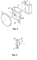
- a cross cylindrical lens 5 is inserted in the correction optical system 1.
- This cross cylinder lens 5 is structured such that the axis of(-) axial cylindrical lens is orthogonal to that of (+) axial cylindrical lens as shown in Fig. 1.
- an intermediate axis 6 of the cross cylindrical lens 5 is allowed to conform to the cylindrical axis O of the cylindrical lens 4.
- the cross cylindrical lens 5 is reversed using the intermediate axis 6 of the cross cylindrical lens 5 as a central axis. Then, the subject is allowed to look at a point group chart 7 of Fig. 3.
- the cylindrical lens 4 and cross cylindrical lens 5 are integrally rotated in a direction where a clear view is obtained by, for example 5 degrees to measure the axial angle A of the cylindrical lens 4 precisely.
- any one of(+) axis and (-) axis of the cross cylindrical lens 5 is confirmed to the cylindrical axis O of the cylindrical lens 4.
- Fig. 4 shows a state in which (+) axis is confirmed, to the cylindrical axis 0.
- the point group chart of Fig. 3 is shown to the subject
- the cross cylinder lens 5 is reversed using the intermediate axis 6 as a central axis and the (-) axis is conformed to the cylindrical axis O.
- the point group chart of Fig. 3 is shown to the subject.
- the cylindrical degree C of the cylindrical lens 2 is set to a direction where a clear view can be obtained.
- an auto cross cylindrical lens 8 shown in Fig. 5 is used.
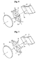
- This auto cross cylindrical lens 8 includes a triangular prism 9 and cross cylindrical lenses 10, 11.
- the cross cylindrical lenses 10 and 11 have the degree of, for example, ⁇ 0. 25D or ⁇ 0.5D, and plus and minus axes of the cross cylindrical lenses 10 and 11 are orthogonal with respect to each other.
- an intermediate axis 12 of the auto cross cylindrical lens 8 is conformed to the cylindrical axis O of the cylindrical lens 4 as shown in Fig. 6. Consequently, the plus axis (+) of the upper-side cross cylinder lens 10 is set to a direction at 45 degrees with respect to the cylindrical axis 0 and the minus axis (-) thereof is set to a direction at 135 degrees. Moreover, the minus axis (-) of the lower-side cross cylinder lens 11 is set to a direction at 45 degrees with respect to the cylindrical axis O and the plus axis (+) thereof is set to a direction at 135 degrees.
- the point group chart 7 of Fig. 3 is similarly shown to the subject so that the subject is allowed to perform comparison between the point group chart 7 seen through the upper-side cross cylinder lens 10 and the point group chart 7 seen through the lower-side cross cylinder lens 11 simultaneously to check which chart can be clearly seen.
- the cylindrical lens 4 is rotated integrally with the auto cross cylinder 8 in the direction where a good view can be obtained.
- the axial angle A of the cylindrical axis O is decided.
- the cross cylinder lenses 10 and 11 are rotated so that the plus axis (+) of the cross cylinder lens 10 is conformed to the cylindrical axis O and the minus (-) of the cross cylinder lens 11 is conformed to the cylindrical axis O as illustrated in Fig. 7.
- the cylindrical degree C of the cylindrical lens 4 which is inserted in the optical path of the correction optical system 1, is changed to the direction where the good view can be obtained.
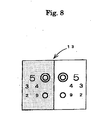
- a so-called red and green chart 13 is shown as illustrated in Fig. 8.
- the spherical degree S of the spherical lens 2 is increased.
- the spherical degree S of the spherical lens 2 is decreased.
- the subject can easily judge which the target can be seen well as compared with the case of using the cross cylinder method.
- this auto cross cylinder method has a disadvantage in which the spherical degree S, cylindrical degree C and axial angle A of cylindrical axis cannot be measured simultaneously.
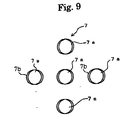
- many subjects answer that the subject can see more easily the respective points 7a whose profile lines 7b are clearly seen in the direction of astigmatic axis as illustrated in a partially enlarged view of Fig. 9, as compared with the respective points 7a of point group chart 7 of Fig. 3 which are blurredly seen uniformly.
- the present invention has been made with consideration given to the aforementioned problems, and it is an object of the present invention is to provide an optometry apparatus that can measure a spherical degree S, a cylindrical degree C and an axial angle A of a cylindrical axis O at one time, so that targets are seen as if they were dispersed in a plane orthogonal to an optical axis and shown simultaneously at a different distance or position in a direction of the optical axis.
- An optometry apparatus comprises an optical element constructed so that targets appear to examined eyes to be subjected to optometry as if the targets were dispersed on a plane orthogonal to an optical axis and shown simultaneously at a different distance or position in a direction of the optical axis.
- the optical element is formed of a diffraction grating plate where periodicity of a diffraction grating changes.
- An optometry apparatus comprises an optical element in a correction optical system which has a spherical lens and a cylindrical lens and corrects eyes to be subjected to optometry, the optical element being constructed such that targets appears to the eyes as if the targets were dispersed in a plane orthogonal to an optical axis and shown simultaneously at a different distance or position in a direction of the optical axis.
- the optical element is capable of going/coming to/from an optical path of the correction optical system.
- optical element is formed of a diffraction grating plate where periodicity of a diffraction grating changes.
- the targets are shown by a single-color light source.
- a subject himself/herself designates a target, which seems to be the best among the plurality of targets shown simultaneously and adjusts said correction optical system.
- matrix signs which can designate the plurality of targets in the form of matrix, are simultaneously shown to the eyes to be subjected to optometry such that the subject himself/herself is caused to designate the target, which seems to be the best among the plurality of targets shown simultaneously.
- the matrix signs are shown in an optical path of the correction optical system through a half mirror.
- the matrix signs are shown with a wavelength by which no diffraction power is generated.
- the subject himself/herself adjusts the correction optical system using a joystick such an target, which seems to be the best among the plurality of targets shown simultaneously, is positioned on an optical axis of the correction optical system.
- the diffraction grating plate is rotated together with the cylindrical lens, so that a spherical degree, a cylindrical degree and an axial angle of a cylindrical axis are precisely measured.
- the diffraction grating plate is rotated by 45 degrees from an initial setting state to determines a spherical degree, a cylindrical degree and an axial angle of a cylindrical axis by calculation.
- a spherical degree, a cylindrical degree and an axial angle of a cylindrical axis are determined by calculation where the spherical degree, the cylindrical degree and the axial angle of cylindrical axis determined by the calculation are synthesized with a cylindrical degree and an axial angle of a cylindrical axis determined by approximate measurement.
- the spherical degree. the cylindrical degree and the axial angle of cylindrical axis are precisely measured by the synthesized spherical degree, cylindrical degree, and axial angle of cylindrical axis obtained by this calculation.
- the diffraction grating plate is rotated by 60 degrees two times from an initial setting state to determine a spherical degree, a cylindrical degree and an axial angle of a cylindrical axis by calculation.
- a spherical degree, a cylindrical degree and an axial angle of a cylindrical axis are determined by calculation where the spherical degree, the cylindrical degree and the axial angle of cylindrical axis determined by the calculation are synthesized with a spherical degree, a cylindrical degree and an axial angle of a cylindrical axis determined by approximate measurement.
- the spherical degree, the cylindrical degree and the axial angle of cylindrical axis are precisely measured by the synthesized spherical degree, cylindrical degree, and axial angle of cylindrical axis determined by this calculation.
- a diffraction grating plate according to the present invention constructed such that targets appear to eyes to be as if the targets were dispersed in a plane orthogonal to an optical axis and shown simultaneously at a different distance or position in a direction of an optical axis through eyes to be subjected to optometry.
- Fig. 10 is an explanatory view showing a schematic structure of an optometry apparatus according to the present invention.
- reference numeral 20 is an examiner
- 21 is a subject
- 22 is a target presenting apparatus
- 23 is a Phoroptor
- 24 is a controller.
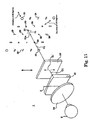
- the Phoroptor 23 is provided with a spherical lens 24 having a different spherical degree S, a cylindrical lens 25 having a different cylindrical degree C and a diffraction grating plate 26 as an optical element as shown in Fig. 11. These spherical lens 24, cylindrical lens 25 and diffraction grating plate 26 are set to an optometric window of the Phoroptor 23 as required.
- Fig. 11 shows a state in which approximate measurement of a spherical degree S, a cylindrical degree C and an axial angle A with respect to examined eyes E subjected to optometry is finished and the spherical lens 24 and the cylindrical lens 25, which serve as correction optical system 1, are inserted in the optometry window.
- the axial angle A of the cylindrical axis O of the cylindrical lens 25 is set to 90 degrees similar to the conventional case.
- the diffraction grating plate 26 is used to carry out precise measurement of an astigmatic axis of the eyes to be subjected to optometry, an astigmatic degree, and a spherical degree.
- the diffraction grating plate 26 is inserted in the optical path of the correction optical system 1 in place of the conventional cross cylindrical lens, and is capable of going/coming to/from the optical path of the correction optical system 1.
- diffraction grating grooves 27 whose periodicity (pitch) continuously changes are formed vertically and horizontally.
- a light beam P is incident from a point source 28 with a single color (short wavelength) through the diffraction grating plate 26, a zero-order light P0, first-order diffraction light P1, second-order diffraction light P2, ... are generated by the respective diffraction gratings as illustrated in Fig. 14.
- the zero-order light P0 is light that travels in a straight line through the diffraction grating plate 26, and the first-order diffraction light P1 is light whose direction is bent by first-order diffraction.
- the second-order diffraction light P2 is light whose direction is bent by first-order diffraction.
- diffraction angles ⁇ 1, ⁇ 2, ⁇ 3, ... of the first-order diffraction light P1 increase in order as the width of the diffraction grating groove 27 becomes narrower. Namely, a relationship, ⁇ 1 ⁇ ⁇ 2 ⁇ 3 ⁇ ..., is established.
- diffraction angles ⁇ 1' ⁇ ⁇ 2' ⁇ ⁇ 3' ⁇ , ... of second-order diffraction light P2 increase in order as the width of diffraction grating groove 27 becomes narrower. Namely, a relationship, ⁇ 1' ⁇ ⁇ 2' ⁇ 3' ⁇ ..., is established.
- the light beam which based on this zero-order diffraction light P0, corresponds to a spherical lens with degree of 0.
- the first-order diffraction light P1 of the upper side acts on a converging direction, so that the first-order diffraction light P1 functions as an imaginary convex lens with given degrees.
- first-order diffraction light P1 of the lower side acts on a diverging direction, so that the first-order diffraction light P1 functions as an imaginary concave lens with given degrees.
- second-order diffraction light P1 of the upper side the diffraction angles ⁇ 1' ⁇ ⁇ 2' ⁇ ⁇ 3' ⁇ , ... increase two times as large as diffraction angles ⁇ 1 ⁇ ⁇ 2 ⁇ ⁇ 3 ⁇ , ...
- the second-order diffraction light P2 of the upper side functions as an imaginary convex lens that has degrees, which are two times as large as an imaginary convex lens with given degrees formed by the first-order diffraction light P1 of the upper side.
- the second-order diffraction light P2 of the lower side functions as an imaginary concave lens that has degrees, which are two times as large as an imaginary concave lens with given degrees formed by the first-order diffraction light P1 of the lower side.
- a plurality of images which are based on the plurality of point sources, are seen on a plane orthogonal to an optical axis O1 and at different distances in a direction of optical axis when seeing the point source 28 with a single color from a direction of an arrow X through the diffraction grating plate 26.
- a radiant image 28' of the point source 28 is seen on the optical axis O1 as illustrated in Fig. 15.
- a circle of confusion image 30 is seen. In this way, the diffraction grating plate 26 can be prepared.
- the diameter of the circle of confusion image increases gradually from the optical axis O1.
- the circle of confusion image 80 exists on the front side in the direction of optical axis O1 and below the optical axis O1
- the circle of confusion image 30 exists on the other side of the optical direction and above the optical axis O1
- the image of light source based on the zero-order diffraction light P0, that of light source based on the first-order diffraction light P1 and that of the second-order diffraction light P2 can have substantially the same intensity.
- the light source (LED) 28 with a single color (abort wavelength) is turned on in synchronization with the insertion of this diffraction grating plate 26. Then, a point target 31a is shown to the eyes E to be subjected to optometry through a pin hole 31a of a pin hole plate 31.
- this point target 31a is seen through the spherical lens 24, cylindrical lens 25, and diffraction grating plate 26 of the correction optical system 1, a plurality of target images are seen as if they were dispersed on a plane orthogonal to the optical axis O1 and shown simultaneously and symmetrically at a different distance in a direction of optical axis based on the real point target 31a as illustrated in Fig. 11.
- the point target 31a is seen as if it was positioned on the optical axis O1 as shown in Fig. 11. However, in a case where correction to the eyes E to be subjected to optometry is not ideally made, the point target 31a is seen as if it was placed at a position shifted from the optical axis O1 as shown in Fig. 18.
- the correction optical system 1 is adjusted such that the point target 31a is positioned on the optical axis 01, it is possible to carry out precise measurement of the astigmatic exis and astigmatic degree of the subject.
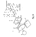
- a half mirror 32 is diagonally provided at the optical path of the correction optical system 1 so that a matrix sign table 33 including numerals and English letters in rows and columns is reflected in the half mirror 32, Then, the numerals and English letters of the matrix sign table 33 are shown to the eyes E to be subjected to optometry simultaneously so that the position of the point target 31a may be designated using the numerals and English letters.
- the matrix sign table 33 is directly displayed in the optical path of the correction optical system 1 with a wavelength by which no diffraction power is produced.
- the joystick 33' is operated in a left direction (direction of an arrow H1). Resultantly, in synchronization with the operation of joystick 33' in a left direction, the degree of the cylindrical lens 25 to be inserted in the optical path of the correction optical system 1 is changed to -0. 25D.
- this operation is continued two times, the position of the point target 31a that can be clearly seen is moved from a position X1 to a position X2.
- the joystick 33' is operated in a direction of an arrow Z1 to increase the degree of the spherical lens 24 to be inserted in the optical path of correction optical system 1 by 0. 25. Resultantly, the position of the point target 31a that can be clearly seen is moved from the position X2 to the optical axis O1.
- the amount of light is reduced by the diffraction function of the diffraction grating plate 26 as compared with the case in which no the diffraction grating plate 26 is inserted.
- the amount of light of the point source 28 may be increased by an amount corresponding to the reduction of the amount of light.
- a spherical degree 8 a cylindrical degree C and an axial angle A of the cylindrical axis 0 are roughly measured by the fogging measurement method.
- the diffraction grating plate 26 is inserted in the optical path of the correction optical system 1.
- the initial setting of the diffraction grating plate 26 to the optical path of the correction optical path 1 is designed such that a direction where one diffraction grating groove 27 extends is a vertical direction.
- an arrow Z1' shows a direction where one diffraction grating groove 27 extends
- the point source 28 with a single color is turned on. Then, the subject is caused to pay attention to the diagonal directions (45 degrees, 135 degrees) shown in Fig. 11.
- the degree of spherical lens is changed to adjust the point target 31a to be positioned on substantially the optical axis O1.
- precise measurement of the spherical degree S is carried out.
- the direction where the diffraction grating groove 27 of the diffraction grating plate 26 extends is roughly conformed to the direction where the cylindrical axis O extends.
- the cylindrical axis O is conformed to the direction Z1' where one diffraction grating groove 27 extends.
- the cylindrical degree C of the cylindrical lens 25 is changed and adjusted by 0. 25D such that the length and clearness of the focal line images 29, which intersect at right angles, become symmetric with respect to the point target 31a. This carries out precise measurement of the cylindrical degree C.
- the diffraction grating plate 26 is inserted in the correction optical system 1, and the diffraction grating plate 26 is subjected to initial setting such that a direction where one diffraction grating groove 27 extends is a vertical direction. Then, the subject is caused to designate the position where the point target 31a. can be seen using the joystick 33' in the initial setting state of the diffraction grating plate 26.
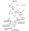
- a program that associates each position, which is seen as being discrete spatially, with power (which is used as concept including the cylindrical degree, convex and concave) of the cylindrical lens is installed onto the controller 24.
- the controller 24 has a program that computes the spherical degree S of the position where the point target can be seen, the cylindrical degree C and axial angle A of cylindrical axis O based on power of the cylindrical lens in the vertical direction, which corresponds to the position where the subject can see the point target 31a, and power of the cylindrical lens in the horizontal direction.
- the cross cylindrical lens is obtained when axes of two cylindrical lenses, each having a different sign and the same refractive power, are orthogonal to each other and combined. This can be expressed as a combination of a spherical lens and a cylindrical lens, and can be represented by the same equation as used in the toric lens.
- D ⁇ 0 (S 1 + S 2 + (C 1 + C 2 )/2) - C 1 /2 (cos2 ⁇ cos2A 1 + sin2 ⁇ sin2A 1 ) - C 2 /2 (cos2 ⁇ cos2A 2 + sin2 ⁇ sin2A 2 )
- the spherical degree S 0 , cylindrical degree C 0 and axial angle A 0 of cylindrical axis O of the composite refractive power D ⁇ 0 obtained by combining two toric lenses can be obtained from equations (g) to (i).
- the composite spherical degree S 0 , cylindrical degree C 0 , and axial angle A 0 are calculated based on the spherical degree S 0 , cylindrical degree C 0 and axial angle A 0 thus obtained and the spherical degree s, cylindrical degree C and axial angle A obtained by the approximate measurement.
- the spherical lens 24 and cylindrical lens 25, which correspond to the composite spherical degree S 0 , cylindrical degree C 0 , and axial angle A 0 are set to the correction optical eyptem 1.
- the axial angle A 0 of cylindrical lens 25 is also conformed to the composite axial angle A.
- the diffraction grating plate 26 is rotated about optical axis O1 by 45 degrees, and the subject is caused to designate the position where the point target 31a can be seen using the joystick 33' in a like manner.
- the spherical degree S, cylindrical degree C, and axial angle A of cylindrical axis O at the position where the point subject 31a can be seen are obtained by calculation. Then, the composite spherical degree S, cylindrical degree C and axial angle A of cylindrical axis O including the spherical degree S, cylindrical degree C, and axial angle A of cylindrical axis O obtained by this calculation and the spherical degree S, cylindrical degree C and axial angle of cylindrical axis O obtained by the approximate measurement are obtained.
- the diffraction grating plate 26 having only the diffraction grating groove 27, which extends longer horizontally. is used.
- a target 35 with three lines, which extend longer vertically, is used. This target 36 is illuminated by the light source 28 with a single color
- a plurality of target images 36 (five) can be seen.
- eyesight of the eyes E to be subjected to optometry is normal or subjected to correction ideally, that is, the astigmatic axis is adjusted and eyesight is normal, the length of the target image 36 on the optical axis O1 is seen in a state that the length is short and the lines in the vertical direction are uniformly seen clearly.
- the length of the target image 36 which is placed at the position shifted from the optical axis O1 is the shortest and the image can be clearly seen.
- Other target images 36 are seen blurrily.
- the spherical degree S, cylindrical degree C, and axial angle A of cylindrical axis O are obtained based on the above. Then, the composite spherical degree S, cylindrical degree C and axial angle A of cylindrical axis 0 are calculated based on the spherical degree S, cylindrical degree C, and axial angle A of cylindrical axis 0 obtained by the calculation and the spherical degree S, cylindrical degree C and axial angle of cylindrical axis 0 obtained by the approximate measurement.
- the spherical lens 24 and cylindrical lens 25, which correspond to the composite spherical degree S, cylindrical degree C, and axial angle A of cylindrical axis O, are set to the correction optical system 1. At this time, the axial angle A of cylindrical axis O of cylindrical lens 25 is also conformed to the composite axial angle A.
- the diffraction grating plate 26 is rotated about the optical axis O1 by 60 degrees, and the subject is caused to designate the position of target image 36, which is clearly seen as compared with the other target images 36, using the joystick 33', again,
- the composite spherical degree S, cylindrical degree C and axial angle A of cylindrical axis O are calculated. Then, the spherical lens and cylindrical lens, which correspond to the composite spherical degree S, cylindrical degree C, and axial angle A of cylindrical axis O are set to the correction optical system 1. Then, the diffraction grating plate 26 is rotated about the optical axis O1 by 60 degrees, again.
- the subject is caused to designate the position of target image 36, which is clearly seen as compared with the other target images 36, using the joystick 33', again.
- the present invention it is possible to precisely measure the spherical degree, angle of astigmatic degree, and astigmatic degree at one time. Moreover, it is possible to make the correction optical system of optometry compact.
Landscapes
- Life Sciences & Earth Sciences (AREA)
- Health & Medical Sciences (AREA)
- Surgery (AREA)
- Animal Behavior & Ethology (AREA)
- Ophthalmology & Optometry (AREA)
- Engineering & Computer Science (AREA)
- Biomedical Technology (AREA)
- Heart & Thoracic Surgery (AREA)
- Medical Informatics (AREA)
- Molecular Biology (AREA)
- Physics & Mathematics (AREA)
- Biophysics (AREA)
- General Health & Medical Sciences (AREA)
- Public Health (AREA)
- Veterinary Medicine (AREA)
- Eye Examination Apparatus (AREA)
- Diffracting Gratings Or Hologram Optical Elements (AREA)
- Lenses (AREA)
- Investigating Or Analysing Materials By Optical Means (AREA)
- Analysing Materials By The Use Of Radiation (AREA)
Applications Claiming Priority (2)
| Application Number | Priority Date | Filing Date | Title |
|---|---|---|---|
| JP2001123245 | 2001-04-20 | ||
| JP2001123245A JP2002315724A (ja) | 2001-04-20 | 2001-04-20 | 検眼装置及びそれに用いる回折格子板 |
Publications (3)
| Publication Number | Publication Date |
|---|---|
| EP1250883A2 true EP1250883A2 (fr) | 2002-10-23 |
| EP1250883A3 EP1250883A3 (fr) | 2003-10-08 |
| EP1250883B1 EP1250883B1 (fr) | 2006-08-30 |
Family
ID=18972833
Family Applications (1)
| Application Number | Title | Priority Date | Filing Date |
|---|---|---|---|
| EP02090150A Expired - Lifetime EP1250883B1 (fr) | 2001-04-20 | 2002-04-22 | Dispositif d'optometrie comportant un réseau diffractif |
Country Status (5)
| Country | Link |
|---|---|
| US (1) | US6749303B2 (fr) |
| EP (1) | EP1250883B1 (fr) |
| JP (1) | JP2002315724A (fr) |
| AT (1) | ATE337724T1 (fr) |
| DE (1) | DE60214272D1 (fr) |
Cited By (2)
| Publication number | Priority date | Publication date | Assignee | Title |
|---|---|---|---|---|
| FR3019459A1 (fr) * | 2014-04-08 | 2015-10-09 | Essilor Int | Lunettes de compensation visuelle et procede de refraction subjective d'un individu portant ces lunettes |
| CN108307619A (zh) * | 2015-06-23 | 2018-07-20 | 依视路国际公司 | 验光测量表 |
Families Citing this family (8)
| Publication number | Priority date | Publication date | Assignee | Title |
|---|---|---|---|---|
| JP4494075B2 (ja) * | 2004-04-16 | 2010-06-30 | 株式会社トプコン | 検眼装置 |
| CN1331437C (zh) * | 2004-08-03 | 2007-08-15 | 温州医学院附属第二医院 | 显微定量角膜检查镜 |
| JP4851176B2 (ja) * | 2005-12-05 | 2012-01-11 | 株式会社トプコン | 視標提示光学装置 |
| JP5079347B2 (ja) * | 2007-01-31 | 2012-11-21 | 株式会社ニデック | 視標呈示装置 |
| US8690332B2 (en) | 2010-10-15 | 2014-04-08 | Epico, Llc | Binocular glare testing devices |
| FR3059537B1 (fr) * | 2016-12-07 | 2019-05-17 | Essilor International | Appareil et procede de mesure de refraction oculaire subjective de haute resolution en puissance optique spherique et/ou cylindrique |
| US10562190B1 (en) * | 2018-11-12 | 2020-02-18 | National Central University | Tactile sensor applied to a humanoid robots |
| JP7476569B2 (ja) * | 2019-03-01 | 2024-05-01 | 株式会社ニデック | 自覚式検眼装置及び自覚式検眼プログラム |
Family Cites Families (6)
| Publication number | Priority date | Publication date | Assignee | Title |
|---|---|---|---|---|
| GB865361A (en) | 1957-06-12 | 1961-04-12 | Wilhelmus Johannes Biessels | Improvements in optical apparatus for testing the human eye |
| US3880502A (en) * | 1972-06-15 | 1975-04-29 | Humphrey Instruments Inc | Ophthalmological apparatus and process having independent astigmatic and spherical inputs |
| US5619373A (en) * | 1995-06-07 | 1997-04-08 | Hasbro, Inc. | Optical system for a head mounted display |
| JP3286133B2 (ja) * | 1995-11-09 | 2002-05-27 | シャープ株式会社 | 拡大用レンズとディスプレイ装置 |
| JP3509377B2 (ja) * | 1996-04-12 | 2004-03-22 | 株式会社ニコン | 曲率測定装置 |
| CA2214260C (fr) | 1997-08-29 | 2007-01-16 | Eyelogic Inc. | Methode et dispositif pour test oculaire |
-
2001
- 2001-04-20 JP JP2001123245A patent/JP2002315724A/ja active Pending
-
2002
- 2002-04-19 US US10/125,907 patent/US6749303B2/en not_active Expired - Fee Related
- 2002-04-22 AT AT02090150T patent/ATE337724T1/de not_active IP Right Cessation
- 2002-04-22 EP EP02090150A patent/EP1250883B1/fr not_active Expired - Lifetime
- 2002-04-22 DE DE60214272T patent/DE60214272D1/de not_active Expired - Lifetime
Cited By (4)
| Publication number | Priority date | Publication date | Assignee | Title |
|---|---|---|---|---|
| FR3019459A1 (fr) * | 2014-04-08 | 2015-10-09 | Essilor Int | Lunettes de compensation visuelle et procede de refraction subjective d'un individu portant ces lunettes |
| WO2015155456A1 (fr) * | 2014-04-08 | 2015-10-15 | Essilor International (Compagnie Generale D'optique) | Lunettes de compensation visuelle et procede de refraction subjective d'un individu portant ces lunettes |
| US10278573B2 (en) | 2014-04-08 | 2019-05-07 | Essilor International | Corrective eyeglasses and method for subjective refraction by a wearer of said eyeglasses |
| CN108307619A (zh) * | 2015-06-23 | 2018-07-20 | 依视路国际公司 | 验光测量表 |
Also Published As
| Publication number | Publication date |
|---|---|
| ATE337724T1 (de) | 2006-09-15 |
| DE60214272D1 (de) | 2006-10-12 |
| US6749303B2 (en) | 2004-06-15 |
| US20020167641A1 (en) | 2002-11-14 |
| EP1250883A3 (fr) | 2003-10-08 |
| JP2002315724A (ja) | 2002-10-29 |
| EP1250883B1 (fr) | 2006-08-30 |
Similar Documents
| Publication | Publication Date | Title |
|---|---|---|
| US8783871B2 (en) | Near eye tool for refractive assessment | |
| US7963654B2 (en) | Apparatus and method for subjective determination of the refractive error of the eye | |
| EP1250883A2 (fr) | Dispositif d'optometrie et réseau diffractif utilisé pour ce dispositif | |
| EP2235587A1 (fr) | Utilisation d'une cible de fixation et dispositif correspondant | |
| Van Meeteren et al. | Image quality of the human eye for eccentric entrance pupils | |
| US20160029885A1 (en) | Image refraction system and method | |
| US7688431B1 (en) | Dispersion demonstrator for eyewear lenses | |
| Katz | Visual acuity through Fresnel, refractive, and hybrid diffractive/refractive prisms | |
| DE102021133152A1 (de) | Verfahren, Vorrichtung und Computerprogrammprodukt zum Bestimmen einer Sensitivität zumindest eines Auges eines Probanden | |
| KR102681570B1 (ko) | 사람의 적어도 하나의 눈의 굴절력을 결정하기 위한 방법 및 시스템 | |
| KR102797369B1 (ko) | 피검자의 주시안을 정량화하는 방법 및 피검자의 주시안을 정량화하는 방법을 구현하기 위한 장치 | |
| CN120751974A (zh) | 用于针对个体的每只眼睛确定矫正镜片的视力矫正焦度的中间视觉值的验光系统 | |
| CN119698571A (zh) | 眼镜镜片的确定方法以及眼镜镜片的确定辅助系统 | |
| US7407290B2 (en) | Method of inspecting monocular diplopia and eye mark pattern for use in the same | |
| EP3691515B1 (fr) | Système et procédé de détermination de valeurs caractéristiques d'une amétropie d'un sujet | |
| EP4437935A1 (fr) | Dispositif d'optométrie pour tester les yeux d'un individu, procédé et produit programme d'ordinateur associés | |
| EP4216799B1 (fr) | Appareil et procédé de détermination d'une erreur de réfraction de l' il | |
| Zhang | Ocular chromatic aberrations and their effects on polychromatic retinal image quality | |
| Mouroulis et al. | Aberration balancing in the design of visually coupled lens systems | |
| DE102024101088A1 (de) | Optische Anordnung zur Bestimmung der objektiven und subjektiven Refraktion und der Zentrierung der Augen und Verfahren zu deren Betrieb | |
| DE102024202065A1 (de) | Optisches System für eine virtuelle Netzhautanzeige (Retinal Scan Display) | |
| DE102021214978A1 (de) | Fixationstarget, Zentriervorrichtung, Verwendung und Verfahren | |
| Mouroulis | Visual target detection and recognition |
Legal Events
| Date | Code | Title | Description |
|---|---|---|---|
| PUAI | Public reference made under article 153(3) epc to a published international application that has entered the european phase |
Free format text: ORIGINAL CODE: 0009012 |
|
| AK | Designated contracting states |
Kind code of ref document: A2 Designated state(s): AT BE CH CY DE DK ES FI FR GB GR IE IT LI LU MC NL PT SE TR |
|
| AX | Request for extension of the european patent |
Free format text: AL;LT;LV;MK;RO;SI |
|
| PUAL | Search report despatched |
Free format text: ORIGINAL CODE: 0009013 |
|
| AK | Designated contracting states |
Kind code of ref document: A3 Designated state(s): AT BE CH CY DE DK ES FI FR GB GR IE IT LI LU MC NL PT SE TR |
|
| AX | Request for extension of the european patent |
Extension state: AL LT LV MK RO SI |
|
| 17P | Request for examination filed |
Effective date: 20040323 |
|
| AKX | Designation fees paid |
Designated state(s): AT BE CH CY DE DK ES FI FR GB GR IE IT LI LU MC NL PT SE TR |
|
| 17Q | First examination report despatched |
Effective date: 20040701 |
|
| GRAP | Despatch of communication of intention to grant a patent |
Free format text: ORIGINAL CODE: EPIDOSNIGR1 |
|
| RTI1 | Title (correction) |
Free format text: OPTOMETRY APPARATUS COMPRISING A DIFFRACTION GRATING PLATE |
|
| GRAS | Grant fee paid |
Free format text: ORIGINAL CODE: EPIDOSNIGR3 |
|
| GRAA | (expected) grant |
Free format text: ORIGINAL CODE: 0009210 |
|
| AK | Designated contracting states |
Kind code of ref document: B1 Designated state(s): AT BE CH CY DE DK ES FI FR GB GR IE IT LI LU MC NL PT SE TR |
|
| PG25 | Lapsed in a contracting state [announced via postgrant information from national office to epo] |
Ref country code: IT Free format text: LAPSE BECAUSE OF FAILURE TO SUBMIT A TRANSLATION OF THE DESCRIPTION OR TO PAY THE FEE WITHIN THE PRESCRIBED TIME-LIMIT;WARNING: LAPSES OF ITALIAN PATENTS WITH EFFECTIVE DATE BEFORE 2007 MAY HAVE OCCURRED AT ANY TIME BEFORE 2007. THE CORRECT EFFECTIVE DATE MAY BE DIFFERENT FROM THE ONE RECORDED. Effective date: 20060830 Ref country code: LI Free format text: LAPSE BECAUSE OF FAILURE TO SUBMIT A TRANSLATION OF THE DESCRIPTION OR TO PAY THE FEE WITHIN THE PRESCRIBED TIME-LIMIT Effective date: 20060830 Ref country code: AT Free format text: LAPSE BECAUSE OF FAILURE TO SUBMIT A TRANSLATION OF THE DESCRIPTION OR TO PAY THE FEE WITHIN THE PRESCRIBED TIME-LIMIT Effective date: 20060830 Ref country code: BE Free format text: LAPSE BECAUSE OF FAILURE TO SUBMIT A TRANSLATION OF THE DESCRIPTION OR TO PAY THE FEE WITHIN THE PRESCRIBED TIME-LIMIT Effective date: 20060830 Ref country code: NL Free format text: LAPSE BECAUSE OF FAILURE TO SUBMIT A TRANSLATION OF THE DESCRIPTION OR TO PAY THE FEE WITHIN THE PRESCRIBED TIME-LIMIT Effective date: 20060830 Ref country code: CH Free format text: LAPSE BECAUSE OF FAILURE TO SUBMIT A TRANSLATION OF THE DESCRIPTION OR TO PAY THE FEE WITHIN THE PRESCRIBED TIME-LIMIT Effective date: 20060830 Ref country code: FI Free format text: LAPSE BECAUSE OF FAILURE TO SUBMIT A TRANSLATION OF THE DESCRIPTION OR TO PAY THE FEE WITHIN THE PRESCRIBED TIME-LIMIT Effective date: 20060830 |
|
| REG | Reference to a national code |
Ref country code: GB Ref legal event code: FG4D |
|
| REG | Reference to a national code |
Ref country code: CH Ref legal event code: EP |
|
| REG | Reference to a national code |
Ref country code: IE Ref legal event code: FG4D |
|
| REF | Corresponds to: |
Ref document number: 60214272 Country of ref document: DE Date of ref document: 20061012 Kind code of ref document: P |
|
| PG25 | Lapsed in a contracting state [announced via postgrant information from national office to epo] |
Ref country code: SE Free format text: LAPSE BECAUSE OF FAILURE TO SUBMIT A TRANSLATION OF THE DESCRIPTION OR TO PAY THE FEE WITHIN THE PRESCRIBED TIME-LIMIT Effective date: 20061130 Ref country code: DK Free format text: LAPSE BECAUSE OF FAILURE TO SUBMIT A TRANSLATION OF THE DESCRIPTION OR TO PAY THE FEE WITHIN THE PRESCRIBED TIME-LIMIT Effective date: 20061130 |
|
| PG25 | Lapsed in a contracting state [announced via postgrant information from national office to epo] |
Ref country code: DE Free format text: LAPSE BECAUSE OF FAILURE TO SUBMIT A TRANSLATION OF THE DESCRIPTION OR TO PAY THE FEE WITHIN THE PRESCRIBED TIME-LIMIT Effective date: 20061201 |
|
| PG25 | Lapsed in a contracting state [announced via postgrant information from national office to epo] |
Ref country code: ES Free format text: LAPSE BECAUSE OF FAILURE TO SUBMIT A TRANSLATION OF THE DESCRIPTION OR TO PAY THE FEE WITHIN THE PRESCRIBED TIME-LIMIT Effective date: 20061211 |
|
| PG25 | Lapsed in a contracting state [announced via postgrant information from national office to epo] |
Ref country code: PT Free format text: LAPSE BECAUSE OF FAILURE TO SUBMIT A TRANSLATION OF THE DESCRIPTION OR TO PAY THE FEE WITHIN THE PRESCRIBED TIME-LIMIT Effective date: 20070212 |
|
| REG | Reference to a national code |
Ref country code: CH Ref legal event code: PL |
|
| NLV1 | Nl: lapsed or annulled due to failure to fulfill the requirements of art. 29p and 29m of the patents act | ||
| EN | Fr: translation not filed | ||
| PLBE | No opposition filed within time limit |
Free format text: ORIGINAL CODE: 0009261 |
|
| STAA | Information on the status of an ep patent application or granted ep patent |
Free format text: STATUS: NO OPPOSITION FILED WITHIN TIME LIMIT |
|
| 26N | No opposition filed |
Effective date: 20070531 |
|
| PG25 | Lapsed in a contracting state [announced via postgrant information from national office to epo] |
Ref country code: GR Free format text: LAPSE BECAUSE OF FAILURE TO SUBMIT A TRANSLATION OF THE DESCRIPTION OR TO PAY THE FEE WITHIN THE PRESCRIBED TIME-LIMIT Effective date: 20061201 Ref country code: FR Free format text: LAPSE BECAUSE OF FAILURE TO SUBMIT A TRANSLATION OF THE DESCRIPTION OR TO PAY THE FEE WITHIN THE PRESCRIBED TIME-LIMIT Effective date: 20070511 |
|
| PG25 | Lapsed in a contracting state [announced via postgrant information from national office to epo] |
Ref country code: IE Free format text: LAPSE BECAUSE OF NON-PAYMENT OF DUE FEES Effective date: 20070423 |
|
| PG25 | Lapsed in a contracting state [announced via postgrant information from national office to epo] |
Ref country code: FR Free format text: LAPSE BECAUSE OF FAILURE TO SUBMIT A TRANSLATION OF THE DESCRIPTION OR TO PAY THE FEE WITHIN THE PRESCRIBED TIME-LIMIT Effective date: 20060830 |
|
| PG25 | Lapsed in a contracting state [announced via postgrant information from national office to epo] |
Ref country code: MC Free format text: LAPSE BECAUSE OF NON-PAYMENT OF DUE FEES Effective date: 20070430 |
|
| PG25 | Lapsed in a contracting state [announced via postgrant information from national office to epo] |
Ref country code: LU Free format text: LAPSE BECAUSE OF NON-PAYMENT OF DUE FEES Effective date: 20070422 Ref country code: CY Free format text: LAPSE BECAUSE OF FAILURE TO SUBMIT A TRANSLATION OF THE DESCRIPTION OR TO PAY THE FEE WITHIN THE PRESCRIBED TIME-LIMIT Effective date: 20060830 |
|
| PG25 | Lapsed in a contracting state [announced via postgrant information from national office to epo] |
Ref country code: TR Free format text: LAPSE BECAUSE OF FAILURE TO SUBMIT A TRANSLATION OF THE DESCRIPTION OR TO PAY THE FEE WITHIN THE PRESCRIBED TIME-LIMIT Effective date: 20060830 |
|
| REG | Reference to a national code |
Ref country code: GB Ref legal event code: 746 Effective date: 20111004 |
|
| PGFP | Annual fee paid to national office [announced via postgrant information from national office to epo] |
Ref country code: GB Payment date: 20150422 Year of fee payment: 14 |
|
| GBPC | Gb: european patent ceased through non-payment of renewal fee |
Effective date: 20160422 |
|
| PG25 | Lapsed in a contracting state [announced via postgrant information from national office to epo] |
Ref country code: GB Free format text: LAPSE BECAUSE OF NON-PAYMENT OF DUE FEES Effective date: 20160422 |