EP1251627A2 - Elektromotorischer Antrieb - Google Patents
Elektromotorischer Antrieb Download PDFInfo
- Publication number
- EP1251627A2 EP1251627A2 EP02007591A EP02007591A EP1251627A2 EP 1251627 A2 EP1251627 A2 EP 1251627A2 EP 02007591 A EP02007591 A EP 02007591A EP 02007591 A EP02007591 A EP 02007591A EP 1251627 A2 EP1251627 A2 EP 1251627A2
- Authority
- EP
- European Patent Office
- Prior art keywords
- housing
- drive according
- housing part
- chamber
- electromotive drive
- Prior art date
- Legal status (The legal status is an assumption and is not a legal conclusion. Google has not performed a legal analysis and makes no representation as to the accuracy of the status listed.)
- Withdrawn
Links
Images



Classifications
-
- H—ELECTRICITY
- H05—ELECTRIC TECHNIQUES NOT OTHERWISE PROVIDED FOR
- H05K—PRINTED CIRCUITS; CASINGS OR CONSTRUCTIONAL DETAILS OF ELECTRIC APPARATUS; MANUFACTURE OF ASSEMBLAGES OF ELECTRICAL COMPONENTS
- H05K7/00—Constructional details common to different types of electric apparatus
- H05K7/14—Mounting supporting structure in casing or on frame or rack
- H05K7/1422—Printed circuit boards receptacles, e.g. stacked structures, electronic circuit modules or box like frames
- H05K7/1427—Housings
- H05K7/1432—Housings specially adapted for power drive units or power converters
Definitions
- the invention relates to an electric motor drive, in particular for furniture, with at least one drive train which can be driven by a motor and which is located in a Housing is arranged, and with a control unit arranged in a control housing and with a power supply device containing at least one transformer.
- the electric motor drive in question is known in many versions. It can be used as a single drive with a motor and a drive train or be designed as a drive with multiple motors and multiple drive trains.
- the drives are equipped with direct current or alternating current motors, which operate via the Control unit via relay and / or electronic switching means via operating devices or manual switch can be operated, the control signals wireless or can be transmitted by wire.
- the operating voltage of which is indicated by a the transformer connected to the power supply network is provided.
- the down-converted alternating current is generated directly or after Rectification and screening used as direct current for the motor supply.
- Such drives have proven themselves in practice. However, they are different Applied areas, for example as drives for furniture in the Apartment, as drives for furniture in a nursing home, as drives for wet rooms or as drives in the hospital area. For the different areas of application there are also different requirements. This is especially true for the tightness of the housing and in particular the control housing. So Existing housings or control housings can be expensive retrofit, but it is often due to the relatively small installation space on the furniture is not possible, so that, for example, the tightness-increasing cover hoods are not usable. It is also known that the housing by special Seals are sealed in a complex manner, which means additional Parts become necessary, so that the variety of parts is increased even further.
- the invention has for its object an electric motor drive type described in the beginning so that the number of total required components is significantly reduced. Furthermore, it should be achieved that at least the control housing exhibits such a tightness that the requirements in the hospital and wet room area.
- control housing of the control unit as Multi-chamber housing is formed, and that preferably the one electrical or electronic assembly-forming components in a common chamber are arranged, and that the control housing outside the housing of the electromotive Drive or outside on the housing of the electromotive drive placeable.
- the control housing is completely separate from the electric motor drive now all control components including the supply voltage sources and enables all additional functions, e.g. the connection of external sensors, Accumulators and the like. Since the components forming the assembly in one Chamber are arranged, the sealing is possible in the simplest way. In order to mechanical fasteners are at least partially dispensed with, that resilient locking tongues for screwless in all or in certain chambers Attachment of electrical and / or electronic components are provided. For example, the control board inserted into a chamber can be replaced by the resilient ones Snap tongues can be set. Furthermore, the transformer can also can be fixed using adjusted spring latches. By the individual Chambers also achieve a high standard of security.
- the housing consists of a one-piece open and one-piece housing part a flat cover that is attached to the housing part, for example by screws connected is.
- the housing part is designed so that the components from below in the housing can preferably be used by automatic assembly machines.
- a Safe and inexpensive coverage is achieved by the outer edge area of the flat lid a preferably all-round and in one piece with the Cover formed sealing lip or a sealing web, which preferably is manufactured in a two-component injection molding process.
- the sealing lip or the sealing web expediently engage in the housing part by there a recess or a groove is provided.
- a chamber is expediently designed so that the connector for the power cord is placed in a separate compartment is.
- this connection has two bushings has, for example, offset from each other by 90 degrees. Thereby the power cable can be led straight into the housing part, so that a deflection is avoided.
- the power cord is attached using a holding plate, which is preferred arranged inside the housing part is fixed. This holding plate should too have a bushing to connect the power cord to the board.
- This Mains connection board has at least one bushing and can also fuse record, which are easy to replace.
- One of the chambers should be like this be designed so that one or more transformers can be accommodated.
- the transformers can be of different types, for example a EI core or a toroidal transformer. It could also be a transformer of higher power without lowering the security.
- the holding bars should be designed so that both a rectangular EI core transformer as well as a round toroidal transformer. Furthermore, can each transformer is also secured in position by a screwed-on holding plate become. As a result, there is no need for independent loosening due to different Impacts. Furthermore, it is also provided that as a power supply option a known battery pack on the outside of the housing part by locking can be set. This ensures a network-independent supply. So that the housing can be mounted on the furniture in a variety of ways, and it is also possible to set it up on the floor at least two retaining tabs are formed on the housing part. These holding tabs should preferably be at right angles to the wall of the housing, continue to be used for guide tabs, retaining webs or similar components from existing ones Motors corresponding guide and / or locking means provided
- control housing outside the housing of the electromotive
- the drive is the easiest way to access the control unit possible, for example for installation or maintenance work.
- control housing according to the invention can be used universally for all drives since A wide variety of functions are possible, for which previously different and varied additional equipment with a corresponding variety of parts was necessary. At the same time, the special constructive design means economy especially by shortening assembly times and materials gone up. It is possible to build function modules from existing ones but different drive concepts due to the high degree of integration to be used, whereby a customary new construction is not necessary.
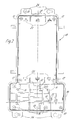
- the housing part 10 of the electromotive drive is in the bare State shown. It is made of plastic and contains several Chambers that are spatially separated from one another by partitions 11.
- the in the Representation according to Figure 1 right chamber has a much greater depth than the left chamber.
- this chamber there are guide and retaining webs 12, 13 for one EI core transformer provided.
- two further guide and holding webs 14, 15 are therefore provided, for example to define a toroidal transformer.
- the transformer used is additionally secured by a holding plate, not shown. These are in the right chamber provided four screw domes 16 to this holding plate set.
- the housing part 10 is also with further screw domes 17 equipped with a cover 18 shown as an individual part in FIG to connect the housing part 10.
- a holding profile 19 is provided for a power cable board, which by a resilient Locking tongue 20 is secured in its position.
- the control board not shown, is in the left chamber of the housing part 10 set. To do this are in this chamber four support webs 21 are provided. The backup is also done by resilient Locking tongues 22.
- the walls delimiting the left chamber are with several Openings 23 provided for motors, controls, sensors, battery connections and the like to connect to the control board, not shown.
- the Figure 1 shows that the receiving the transformer and the power cord board Chambers in depth or height are significantly larger than that receiving the control board Chamber.
- FIG. 2 shows the housing part 10 in a top view.
- the individual components are denoted by the same reference numerals as in FIG. 1.
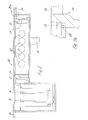
- the figure 3 shows the housing part 10 in vertical section.
- Figure 3 also shows that the chamber of the housing part 10 with the smaller depth on the open side opposite side is provided with a holder 25 for batteries. This means that the electric motor drive can also be operated independently of the network become.
- FIG. 3a shows that the edge delimiting the opening is initially straight runs, and then has an inclined surface, whereby the in the figure 4 lid 18 shown is pulled firmly against the inclined surface 26. Thereby tightness is already achieved. This is increased because the lid in a sealing lip 27 is formed, described in more detail, which in a groove-like Channel 28 engages, as shown in Figure 5.
- FIG. 4 shows the flat cover 18 for the electric motor drive. from that again results that not only the depth or height of the transformers and the power cable board receiving chamber is larger than that of the control board receiving chamber, but that these chambers are also larger in width.
- the cover is provided with several countersunk holes 29 around the fastening screws pass therethrough. These are in the screw domes 17 screwed.
- Figure 5 shows that preferably countersunk screws for fixing of the lid 18 can be used.
- Figure 5 also shows the figure 6 that a circumferential sealing lip 27 is integrally formed on the inside of the lid is.
- FIG. 5 in conjunction with FIG. 7 shows that the bores are self-sealing due to the conical countersink.
- Figure 6 shows in the Connection with FIG. 8 that the cover 18 on the part 10 facing away from the housing outer side is equipped with a raised edge web 30.
- FIG. 8 shows that the cover 18 is also equipped with an inclined surface 26a that contacts the inclined surface 26 of the housing part 10 in the screwed state.
- control housing 10 is not restricted to the exemplary embodiment shown. Essential is that the individual function groups within the control housing 10 are separated from each other by partitions 11 and that without any special precautions the control housing 10 has a tightness, which can also be used in Moisture and wet rooms enabled.
Landscapes
- Engineering & Computer Science (AREA)
- Microelectronics & Electronic Packaging (AREA)
- Casings For Electric Apparatus (AREA)
- Invalid Beds And Related Equipment (AREA)
- Motor Or Generator Frames (AREA)
Abstract
Description
- Figur 1
- das offene Gehäuseteil in einer perspektivischen Darstellung, mit Blick auf die offene Seite,
- Figur 2
- das Gehäuseteil in einer Draufsicht,
- Figur 3
- das Gehäuseteil nach den Figuren 1 und 2 in Schnittdarstellung,
- Figur 3a
- eine Einzelheit 3a nach der Figur 3
- Figur 4
- den Deckel mit Blick auf die Innenfläche
- Figur 5
- einen Schnitt längs der Linie V-V in der Figur 4,
- Figur 6
- einen Schnitt längs der Linie VI-VI in der Figur 4
- Figur 7
- eine Einzelheit VII in der Figur 5 und
- Figur 8
- eine Einzelheit VIII in der Figur 6.
Claims (13)
- Elektromotorischer Antrieb insbesondere für Möbel mit wenigstens einem von einem Motor antreibbaren Antriebszug, welche in einem Gehäuse angeordnet sind und mit einer in einem Steuergehäuse angeordneten Steuereinheit und mit einer wenigstens einen Transformator enthaltenden Stromversorgungseinrichtung, dadurch gekennzeichnet, dass das Steuergehäuse (10) der Steuereinheit als Mehrkammergehäuse ausgebildet ist und dass vorzugsweise die eine elektrische Baugruppe bildenden Bauelemente in einer gemeinsamen Kammer angeordnet sind, und dass das Steuergehäuse (10) außerhalb des Gehäuses des elektromotorischen Antriebes oder außen am Gehäuse des elektromotorischen Antriebs platzierbar ist..
- Elektromotorischer Antrieb nach Anspruch 1, dadurch gekennzeichnet, dass in allen oder in bestimmten Kammern federnde Rastzungen (20, 22) zur schraubenlosen Befestigung von elektrischen und/oder elektronischen Bauteilen vorgesehen sind.
- Elektromotorischer Antrieb nach Anspruch 1 oder 2, dadurch gekennzeichnet, dass das Gehäuse aus einem einseitig offenen und einstückigen Gehäuseteil (10) und einem flachen Deckel (18) besteht.
- Elektromotorischer Antrieb nach einem oder mehreren der vorhergehenden Ansprüche 1 bis 3, dadurch gekennzeichnet, dass in dem äußeren Randbereich des flachen Deckels (18) eine vorzugsweise umlaufende und einstückig mit dem Deckel (18) ausgebildete Dichtlippe (27) oder ein Dichtsteg angeformt ist, und daß die Dichtlippe oder der Dichtsteg vorzugsweise im Zweikomponenten-Spritzgußverfahren gefertigt ist.
- Elektromotorischer Antrieb nach einem oder mehreren der vorhergehenden Ansprüche 1 bis 4, dadurch gekennzeichnet, dass das Gehäuseteil (10) mit mehreren Anschlüssen für elektrische Kabel ausgestattet ist.
- Elektromotorischer Antrieb nach einem oder mehreren der vorhergehenden Ansprüche 1 bis 5, dadurch gekennzeichnet, dass in einer Kammer eine Netzanschlußplatine durch Rastung festlegbar ist.
- Elektromotorischer Antrieb nach einem oder mehreren der vorhergehenden Ansprüche 1 bis 6, dadurch gekennzeichnet, dass außenseitig am Gehäuseteil (10) mehrere Haltelaschen (24) angeformt sind.
- Elektromotorischer Antrieb nach einem oder mehreren der vorhergehenden Ansprüche 1 bis 7, dadurch gekennzeichnet, dass in einer Kammer derartige Stege vorgesehen sind, dass wahlweise Transformatoren unterschiedlicher Bauarten festlegbar sind.
- Elektromotorischer Antrieb nach einem oder mehreren der vorhergehenden Ansprüche 1 bis 8, dadurch gekennzeichnet, dass außenseitig am Gehäuseteil (10) ein Halteprofil (19) zur Festlegung einer Hilfsspannungsquelle vorgesehen sind.
- Elektromotorischer Antrieb nach einem oder mehereren der vorhergehenden Ansprüche 1 bis 9, dadurch gekennzeichnet, dass der in dem Gehäuseteil (10) festgelegte Transformator mittels einer Halteplatte gesichert ist.
- Elektromotorischer Antrieb nach einem oder mehreren der vorhergehenden Ansprüche 1 bis 10, dadurch gekennzeichnet, dass an einer eine Öffnung dr Gehäusekammer verschließenden Platte aus einer Zugentlastung für ein Netzkabel angeordnet ist oder die Platte als Zugentlastung ausgebildet ist.
- Elektromotorischer Antrieb nach einem oder mehreren der vorhergehenden Ansprüche 1 bis 11, dadurch gekennzeichnet, dass in einer Kammer des Gehäuseteils (10) eine Netzanschlußplatine festlegbar ist, und dass die Netzanschlußplatine mit einer Sicherung oder mit mehreren Sicherungen bestückt ist.
- Elektromotorischer Antrieb nach einem oder mehreren der vorhergehenden Ansprüche 1 bis 12, dadurch gekennzeichnet, dass der Deckel (18) an der dem Gehäuseteil (10) zugewandten Seite eine Schrägfläche (26) aufweist, die eine entsprechend geneigte Schrägfläche (26a) des Gehäuseteils (10) dichtend kontaktiert.
Applications Claiming Priority (2)
| Application Number | Priority Date | Filing Date | Title |
|---|---|---|---|
| DE20106518U | 2001-04-14 | ||
| DE20106518U DE20106518U1 (de) | 2001-04-14 | 2001-04-14 | Elektromotorischer Antrieb |
Publications (2)
| Publication Number | Publication Date |
|---|---|
| EP1251627A2 true EP1251627A2 (de) | 2002-10-23 |
| EP1251627A3 EP1251627A3 (de) | 2004-03-24 |
Family
ID=7955749
Family Applications (1)
| Application Number | Title | Priority Date | Filing Date |
|---|---|---|---|
| EP02007591A Withdrawn EP1251627A3 (de) | 2001-04-14 | 2002-04-04 | Elektromotorischer Antrieb |
Country Status (2)
| Country | Link |
|---|---|
| EP (1) | EP1251627A3 (de) |
| DE (1) | DE20106518U1 (de) |
Cited By (2)
| Publication number | Priority date | Publication date | Assignee | Title |
|---|---|---|---|---|
| WO2005101936A1 (de) * | 2004-04-16 | 2005-10-27 | Siemens Aktiengesellschaft | Gehäuse für motorsteuergeräte |
| DE202007015937U1 (de) * | 2007-11-13 | 2009-03-19 | Dewert Antriebs- Und Systemtechnik Gmbh | Elektromotorische Möbelantriebseinrichtung |
Families Citing this family (2)
| Publication number | Priority date | Publication date | Assignee | Title |
|---|---|---|---|---|
| DE102008050255B4 (de) * | 2008-10-07 | 2015-10-08 | Dewertokin Gmbh | Linearantrieb |
| US8957752B2 (en) | 2011-10-07 | 2015-02-17 | Sabic Global Technologies B.V. | Inverter housing system |
Family Cites Families (12)
| Publication number | Priority date | Publication date | Assignee | Title |
|---|---|---|---|---|
| DE1808354U (de) * | 1959-09-12 | 1960-03-24 | Stotz Kontakt Gmbh | Vorrichtung zur verhinderung von kondenswasseransammlungen in gehaeusen elektrischer geraete. |
| GB1227292A (de) * | 1968-04-11 | 1971-04-07 | ||
| US4092698A (en) * | 1976-09-16 | 1978-05-30 | Analog Devices, Incorporated | Protective case for electrical instruments on circuit boards |
| JPH0834714B2 (ja) * | 1987-06-16 | 1996-03-29 | ファナック株式会社 | Acスピンドルアンプの筐体構造 |
| US4810897A (en) * | 1987-07-01 | 1989-03-07 | Shotey Michael J | Timer assembly with weatherproof housing |
| DE9013006U1 (de) | 1990-09-12 | 1991-07-04 | Siemens AG, 80333 München | Kommutator-Getriebe-Antriebseinheit, insbesondere Fensterheberantrieb für ein Kraftfahrzeug |
| DE29601526U1 (de) * | 1996-01-30 | 1997-06-05 | AEG Zähler GmbH, 31785 Hameln | Gehäuse eines elektronischen Elektrizitätszählers |
| IT240458Y1 (it) * | 1996-02-20 | 2001-04-02 | Abb Lucasystem S R L | Guarnizione per scatola a tenuta stagna |
| DE19643301A1 (de) | 1996-10-21 | 1998-04-23 | Maico Elektroapparate | Ventilator-Elektromotor mit umgestaltbarem Gehäuse |
| DE19723913A1 (de) | 1997-06-06 | 1998-12-24 | Loher Ag | Explosionsgeschützter Asynchronmotor |
| DE29803957U1 (de) * | 1998-02-19 | 1998-04-23 | ANKARO Otto Wolf KG, 44536 Lünen | Montagegehäuse für ein elektronisches Gerät |
| DE20005050U1 (de) | 2000-03-20 | 2000-05-18 | Dewert Antriebs Systemtech | Elektromotorischer Linearantrieb |
-
2001
- 2001-04-14 DE DE20106518U patent/DE20106518U1/de not_active Expired - Lifetime
-
2002
- 2002-04-04 EP EP02007591A patent/EP1251627A3/de not_active Withdrawn
Cited By (2)
| Publication number | Priority date | Publication date | Assignee | Title |
|---|---|---|---|---|
| WO2005101936A1 (de) * | 2004-04-16 | 2005-10-27 | Siemens Aktiengesellschaft | Gehäuse für motorsteuergeräte |
| DE202007015937U1 (de) * | 2007-11-13 | 2009-03-19 | Dewert Antriebs- Und Systemtechnik Gmbh | Elektromotorische Möbelantriebseinrichtung |
Also Published As
| Publication number | Publication date |
|---|---|
| EP1251627A3 (de) | 2004-03-24 |
| DE20106518U1 (de) | 2001-06-07 |
Similar Documents
| Publication | Publication Date | Title |
|---|---|---|
| EP0702441B1 (de) | Elektroinstallationsgerät, insbesondere für Kabelkanäle | |
| EP0185107A1 (de) | Motorschutzschalter | |
| EP1402610A1 (de) | Elektromotorischer stelltrieb | |
| DE20106518U1 (de) | Elektromotorischer Antrieb | |
| EP1135013A1 (de) | Türstation | |
| DE10361452A1 (de) | Anordnung zum Befestigen von elektrischen und/oder elektronischen Bauteilen, insbesondere Leistungsbauteilen, an einer Platine und Gehäuse hiermit | |
| DE102007045869B3 (de) | Elektrisches/elektronisches Installationsgerät | |
| DE4013356A1 (de) | Anschlussklemmentraeger fuer eine steckbare verbindung mit einem elektrischen installationsgeraet | |
| DE2917864C2 (de) | Koppelanordnung zur Steuerung elektrischer Verbraucher in schlagwetter- oder explosionsgefährdeter Umgebung | |
| DE102008061908B3 (de) | Steckdosenverteiler | |
| DE3445601A1 (de) | Raumtemperaturregler | |
| DE10314459A1 (de) | Metallgekapselte gasisolierte Schaltanlage | |
| DE3423854C2 (de) | ||
| EP0980200A2 (de) | Moduleinheit für eine Türanlage, insbesondere Türsprechanlage | |
| EP0568795B1 (de) | Niedervolt-Elektrifiziereinrichtung für Kastenmöbel oder Innenausbauten | |
| DE4002470C2 (de) | Befehlsgerät zum Einbau zwischen zwei parallelflächigen Gehäuseteilen | |
| EP0405165B1 (de) | Mobiles Steuergehäuse | |
| DE10016592A1 (de) | Abdeckrahmen-System für elektrische Installationsgeräte | |
| DE20302147U1 (de) | Elektromotorischer Möbelantrieb | |
| EP0676841B1 (de) | Einrichtung zur Versorgung eines elektrisch betätigten Gerätes im Sanitärbereich mit einer Niedervolt-Betriebsspannung | |
| AT405583B (de) | Bauteil für elektroinstallationen | |
| DE9302630U1 (de) | Einrichtung für einen Aktor | |
| DE3034708A1 (de) | Elektrisches installationsgeraet | |
| DE3340658A1 (de) | Gehaeuse fuer elektrische schaltelemente | |
| DE9404835U1 (de) | Bauteil für Elektroinstallationen |
Legal Events
| Date | Code | Title | Description |
|---|---|---|---|
| PUAI | Public reference made under article 153(3) epc to a published international application that has entered the european phase |
Free format text: ORIGINAL CODE: 0009012 |
|
| AK | Designated contracting states |
Kind code of ref document: A2 Designated state(s): AT BE CH CY DE DK ES FI FR GB GR IE IT LI LU MC NL PT SE TR |
|
| AX | Request for extension of the european patent |
Free format text: AL;LT;LV;MK;RO;SI |
|
| PUAL | Search report despatched |
Free format text: ORIGINAL CODE: 0009013 |
|
| AK | Designated contracting states |
Kind code of ref document: A3 Designated state(s): AT BE CH CY DE DK ES FI FR GB GR IE IT LI LU MC NL PT SE TR |
|
| AX | Request for extension of the european patent |
Extension state: AL LT LV MK RO SI |
|
| RIC1 | Information provided on ipc code assigned before grant |
Ipc: 7H 05K 7/14 B Ipc: 7H 05K 5/06 B Ipc: 7H 05K 5/02 B Ipc: 7H 02K 11/00 A |
|
| AKX | Designation fees paid | ||
| REG | Reference to a national code |
Ref country code: DE Ref legal event code: 8566 |
|
| STAA | Information on the status of an ep patent application or granted ep patent |
Free format text: STATUS: THE APPLICATION IS DEEMED TO BE WITHDRAWN |
|
| 18D | Application deemed to be withdrawn |
Effective date: 20040928 |