EP1252811A1 - Grasfangeinrichtung für einen motorbetriebenen Rasenmäher - Google Patents
Grasfangeinrichtung für einen motorbetriebenen Rasenmäher Download PDFInfo
- Publication number
- EP1252811A1 EP1252811A1 EP02006729A EP02006729A EP1252811A1 EP 1252811 A1 EP1252811 A1 EP 1252811A1 EP 02006729 A EP02006729 A EP 02006729A EP 02006729 A EP02006729 A EP 02006729A EP 1252811 A1 EP1252811 A1 EP 1252811A1
- Authority
- EP
- European Patent Office
- Prior art keywords
- grass catcher
- hood
- grass
- lawnmower
- bag
- Prior art date
- Legal status (The legal status is an assumption and is not a legal conclusion. Google has not performed a legal analysis and makes no representation as to the accuracy of the status listed.)
- Granted
Links
- 244000025254 Cannabis sativa Species 0.000 title claims abstract description 64
- 239000000428 dust Substances 0.000 claims description 15
- 239000002245 particle Substances 0.000 claims description 11
- 230000002093 peripheral effect Effects 0.000 abstract 1
- 239000004744 fabric Substances 0.000 description 3
- 239000000463 material Substances 0.000 description 2
- 239000002184 metal Substances 0.000 description 1
- 230000000452 restraining effect Effects 0.000 description 1
Images

Classifications
-
- A—HUMAN NECESSITIES
- A01—AGRICULTURE; FORESTRY; ANIMAL HUSBANDRY; HUNTING; TRAPPING; FISHING
- A01D—HARVESTING; MOWING
- A01D43/00—Mowers combined with apparatus performing additional operations while mowing
- A01D43/06—Mowers combined with apparatus performing additional operations while mowing with means for collecting, gathering or loading mown material
- A01D43/063—Mowers combined with apparatus performing additional operations while mowing with means for collecting, gathering or loading mown material in or into a container carried by the mower; Containers therefor
-
- A—HUMAN NECESSITIES
- A01—AGRICULTURE; FORESTRY; ANIMAL HUSBANDRY; HUNTING; TRAPPING; FISHING
- A01D—HARVESTING; MOWING
- A01D2101/00—Lawn-mowers
-
- A—HUMAN NECESSITIES
- A01—AGRICULTURE; FORESTRY; ANIMAL HUSBANDRY; HUNTING; TRAPPING; FISHING
- A01D—HARVESTING; MOWING
- A01D34/00—Mowers; Mowing apparatus of harvesters
- A01D34/01—Mowers; Mowing apparatus of harvesters characterised by features relating to the type of cutting apparatus
- A01D34/412—Mowers; Mowing apparatus of harvesters characterised by features relating to the type of cutting apparatus having rotating cutters
- A01D34/63—Mowers; Mowing apparatus of harvesters characterised by features relating to the type of cutting apparatus having rotating cutters having cutters rotating about a vertical axis
Definitions
- the invention relates to a grass catcher for one motor-powered lawn mower according to the preamble of the claim 1.
- From US 5,564,265 is a motor-powered lawn mower Known for mowing green areas, on the housing one Grass catcher for collecting crop with the help of a Holding device is attached.
- the grass catcher consists essentially of two slidable Grass bags, the grass bags made of breathable Material are formed.
- the invention has for its object a grass catcher for a motorized lawnmower create, in which the dust exposure of the operator in Operation of the lawnmower is low.
- the grass catcher is intended to hold as much as possible to surround with a hood on all sides, the hood is open to the green area, but otherwise a closed one Represents fabrics. Between the hood and the grass bag is a distance, that is, an air space intended. At least the side surfaces of the grass catcher are spaced from the hood. In this way it is possible that dust particles from the grass catcher be carried out in the air space between the grass catcher and the hood directed to the green area and deposited there become. The operator thus comes with airborne ones Little dust particles in contact.
- the hood is preferably movable on a pivot axis the holding device for the grass catcher set, wherein the swivel axis is approximately transverse to the longitudinal axis of the lawnmower and is aligned approximately parallel to the green area.
- the dead weight of the hood in the operation of the Lawnmower carried by the carrier air stream of the mower.
- the crop is conveyed into the grass catcher, whereby the carrier air penetrates this and the oscillates around the Hinged hood carries pivot axis.
- the holding device may be appropriate to use as one determining the firm frame and the shape of the grass bag train.
- the hood can be rigid the holding device.
- the hood is preferred, in like a quick-release fastener, with tabs, which can be brought into engagement with the frame like a clip.
- the lower edges of the hood are approximately straight and aligned parallel to the green area during operation of the lawnmower. Between the lower edges of the hood and the green area a gap remains so that the carrier air from the Grass catcher can escape. The dust particles in the In this way, carrier air is separated from the green area.
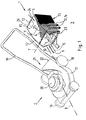
- the motorized lawn mower 2 shown in Fig. 1 is in essentially from a housing 17 with impellers 18 and a guide bar 19 attached to the housing is formed.
- On Motor 20 drives a mower blade, not shown, in housing 17 on.
- the mowing knife causes the crop 9 together with a carrier airflow 10 generated by the mowing knife is from the spiral to the rear 21 of the Lawn mower 2 expanding housing 17 is carried out and arrives in a grass catcher 1.
- the grass catcher 1 is detachable at the mouth 22 of the housing 17 established.
- the grass catcher 1 is shown in the Embodiment as a box-shaped component made of metal, Plastic or other suitable material is formed and consists essentially of a grass bag 4 with a holding device 5.
- the holding device 5 is as frame-like component for detachable fixing of the grass catcher 4 and the mouth 22 of the lawn mower housing 17 is provided.
- the grass bag 4 has a closed, flat Roof part 15 and a bottom part 23.
- the three sides of the grass catcher are as an air-permeable grid or formed on the tissue that lies between the ground and Roof part spanned.
- the fabric or grid 25 is used for Restraining the crop 9 inside the grass catcher 4.
- Carrier airflow 10 may be fabric or grid 25 happen.
- Hood 6 encloses the side surfaces of the grass catcher 4 by a distance of 24 to this.
- the grass catcher 1 is in the embodiment shown in Fig. 1 for rigid attachment provided on the housing 17 of the lawn mower 2. It can be useful, for example, about the maneuverability of the Lawnmower in uneven terrain to improve the grass catcher 1 by approximately horizontal and transverse to Longitudinal axis 8 of the lawn mower 2 pivot axis 7 to be arranged movably on the holding device 5. It can also be useful, the grass bag 4 as a flexible component, which only at the mouth 22 of the housing 17th attached to perform. The grass catcher 4 can then within certain limits under one as a trough-shaped Moving component-formed hood freely, the hood of the carrier air flow 10 over the green area 3 with little Distance is worn like a pillow.
- the holding device 5 for the grass catcher 4 as a fixed frame 11, the determines the spatial shape of the grass catcher 4, trained.
- This has the advantage that the hood is detachably attached to the holding device 5, on the frame 11 so can be set.
- the hood 6 has along its upper edge 26, which faces away from the green area 3, for this purpose, cross-sectionally semicircular tabs 12 on.
- the tabs 12 are suitable, the hood 6 like clips to fix on the frame. Move while the lawnmower 2 is operating the lower edges 13 of the hood 6 approximately parallel and at a short distance from the green area 3.
- FIG. 1 Now step on the crop 9 and the carrier air 10 with corresponding dust particles 14 in the grass catcher 4, the grass catcher holds 4 the crop 9 back and leaves the carrier air 10 together happen with the dust particles 14 to the outside, like this is shown in Fig. 1.
- the hood 6 surrounds one certain distance 24, for example with about 2 cm to 5 cm the grass bag 4, so that between the grass bag and the hood 6, the carrier air 10 with the dust particles 14 the green area 3 is steered.
- the dust particles 14 are thus deposited on the green area 3.
- the dust pollution the operator is due to airborne dust particles 14 minimized in this way.
Landscapes
- Life Sciences & Earth Sciences (AREA)
- Environmental Sciences (AREA)
- Harvester Elements (AREA)
- Catching Or Destruction (AREA)
- Transplanting Machines (AREA)
Abstract
Description
- Fig. 1
- eine schematische Ansicht einer Grasfangeinrichtung an einem motorbetriebenen Rasenmäher,
- Fig. 2
- eine schematische Ansicht eines Grasfangsacks der Grasfangeinrichtung in Fig. 1,
- Fig. 3
- eine schematische Ansicht einer als U-förmig, flächiges Rahmenteil ausgebildeten Haube.
Claims (10)
- Grasfangeinrichtung für einen motorbetriebenen Rasenmäher (2) zum Mähen von Grünflächen (3), bestehend aus einem luftdurchlässigen Grasfangsack (4) mit einer Haltevorrichtung (5) zur lösbaren Festlegung des Grasfangsacks (4) an dem Rasenmäher (2),
dadurch gekennzeichnet, daß der Grasfangsack (4) von einer Haube (6) im wesentlichen allseitig ganzflächig mit Abstand umschlossen ist, wobei die Haube (6) zur Grünfläche (3) geöffnet ist. - Grasfangeinrichtung nach Anspruch 1,
dadurch gekennzeichnet, daß die Haube (6) um eine Schwenkachse (7) beweglich an der Haltevorrichtung (5) festgelegt ist. - Grasfangeinrichtung nach Anspruch 2,
dadurch gekennzeichnet, daß die Schwenkachse (7) etwa quer zur Längsachse (8) des Rasenmähers (2) angeordnet ist. - Grasfangeinrichtung nach einem der Ansprüche 2 oder 3,
dadurch gekennzeichnet, daß die Schwenkachse (7) im Betrieb des Rasenmähers (2) etwa parallel zur Grünfläche (3) ausgerichtet ist. - Grasfangeinrichtung nach einem der Ansprüche 1 bis 4,
dadurch gekennzeichnet, daß die Haube (6) im Betrieb des Rasenmähers (2) von dem das Mähgut (9) in den Grasfangsack (4) fördernden Trägerluftstrom (10) des Rasenmähers (2) getragen ist. - Grasfangeinrichtung nach einem der Ansprüche 1 bis 5,
dadurch gekennzeichnet, daß die Haltevorrichtung (5) ein fester Rahmen (11) ist, der die Raumform des Grasfangsackes (4) bestimmt, wobei die Haube (6) lösbar an der Haltevorrichtung (5) festgelegt ist. - Grasfangeinrichtung nach Anspruch 6,
dadurch gekennzeichnet, daß die Haube (6) mit Laschen (12) versehen ist, die klipsartig am Rahmen (11) festliegen. - Grasfangeinrichtung nach einem der Ansprüche 1 bis 7,
dadurch gekennzeichnet, daß die Unterkanten (13) der Haube (6) im Betrieb des Rasenmähers (2) etwa parallel zur Grünfläche (3) ausgerichtet sind. - Grasfangeinrichtung nach einem der Ansprüche 1 bis 8,
dadurch gekennzeichnet, daß im Betrieb des Rasenmähers (2) Staubpartikel (14) durch den Grasfangsack (4) geführt und durch die Haube (6) zur Grünfläche (3) gelenkt sind. - Grasfangeinrichtung nach einem der Ansprüche 1 bis 9,
dadurch gekennzeichnet, daß der Grasfangsack (4) ein flächiges Dachteil (15) aufweist und die Haube (6) als U-förmiges, den Grasfangsack (4) seitlich umschließendes vollflächiges Rahmenteil (16) gebildet ist.
Applications Claiming Priority (2)
| Application Number | Priority Date | Filing Date | Title |
|---|---|---|---|
| DE20107166U DE20107166U1 (de) | 2001-04-26 | 2001-04-26 | Grasfangeinrichtung für einen motorbetriebenen Rasenmäher |
| DE20107166U | 2001-04-26 |
Publications (2)
| Publication Number | Publication Date |
|---|---|
| EP1252811A1 true EP1252811A1 (de) | 2002-10-30 |
| EP1252811B1 EP1252811B1 (de) | 2007-08-29 |
Family
ID=7956209
Family Applications (1)
| Application Number | Title | Priority Date | Filing Date |
|---|---|---|---|
| EP02006729A Expired - Lifetime EP1252811B1 (de) | 2001-04-26 | 2002-03-23 | Grasfangeinrichtung für einen motorbetriebenen Rasenmäher |
Country Status (4)
| Country | Link |
|---|---|
| EP (1) | EP1252811B1 (de) |
| AT (1) | ATE371365T1 (de) |
| DE (2) | DE20107166U1 (de) |
| ES (1) | ES2292656T3 (de) |
Cited By (1)
| Publication number | Priority date | Publication date | Assignee | Title |
|---|---|---|---|---|
| IT201800007555A1 (it) * | 2018-07-27 | 2020-01-27 | Stiga Spa In Breve Anche St Spa | Sacco per tosaerba con convogliatore d’erba |
Families Citing this family (5)
| Publication number | Priority date | Publication date | Assignee | Title |
|---|---|---|---|---|
| ATE308874T1 (de) * | 2002-07-29 | 2005-11-15 | Werner Kress | Rasenmäher |
| DE102005017405B4 (de) * | 2005-04-15 | 2007-03-29 | Wolf-Geräte AG | Grasfangkorb |
| ITBS20090220A1 (it) * | 2009-12-02 | 2011-06-03 | Agripool S R L A Socio Unico | Tagliaerba e gruppo di raccolta dell'erba tagliata |
| CN101790921B (zh) * | 2010-03-11 | 2012-05-02 | 常州合力电器有限公司 | 防倾倒手推式电动割草机 |
| CN108207292A (zh) * | 2017-12-26 | 2018-06-29 | 黎花英 | 一种园林用小草修剪设备 |
Citations (8)
| Publication number | Priority date | Publication date | Assignee | Title |
|---|---|---|---|---|
| US3421302A (en) * | 1966-08-29 | 1969-01-14 | Outboard Marine Corp | Lawn mower grass catching bag |
| US4745735A (en) * | 1986-01-07 | 1988-05-24 | Kubota, Ltd. | Grass collecting container for grass mower |
| US4836610A (en) * | 1988-01-15 | 1989-06-06 | Brinly-Hardy Co., Inc. | Collector cart |
| EP0610062A1 (de) * | 1993-02-01 | 1994-08-10 | Electrolux Outdoor Products Limited | Sammelbehälter |
| GB2280585A (en) * | 1993-06-04 | 1995-02-08 | Electrolux Northern | A grass collection device for a lawn mower |
| JPH0799820A (ja) * | 1993-09-30 | 1995-04-18 | Kubota Corp | 芝刈り機の集草容器 |
| US5564265A (en) * | 1994-02-28 | 1996-10-15 | Pitt; Leo | Grass catcher insert and adapter for lawn mowers |
| DE19901960A1 (de) * | 1998-01-23 | 1999-07-29 | Bosch Gmbh Robert | Auffangvorrichtung für Gras |
-
2001
- 2001-04-26 DE DE20107166U patent/DE20107166U1/de not_active Expired - Lifetime
-
2002
- 2002-03-23 AT AT02006729T patent/ATE371365T1/de not_active IP Right Cessation
- 2002-03-23 EP EP02006729A patent/EP1252811B1/de not_active Expired - Lifetime
- 2002-03-23 DE DE50210786T patent/DE50210786D1/de not_active Expired - Lifetime
- 2002-03-23 ES ES02006729T patent/ES2292656T3/es not_active Expired - Lifetime
Patent Citations (8)
| Publication number | Priority date | Publication date | Assignee | Title |
|---|---|---|---|---|
| US3421302A (en) * | 1966-08-29 | 1969-01-14 | Outboard Marine Corp | Lawn mower grass catching bag |
| US4745735A (en) * | 1986-01-07 | 1988-05-24 | Kubota, Ltd. | Grass collecting container for grass mower |
| US4836610A (en) * | 1988-01-15 | 1989-06-06 | Brinly-Hardy Co., Inc. | Collector cart |
| EP0610062A1 (de) * | 1993-02-01 | 1994-08-10 | Electrolux Outdoor Products Limited | Sammelbehälter |
| GB2280585A (en) * | 1993-06-04 | 1995-02-08 | Electrolux Northern | A grass collection device for a lawn mower |
| JPH0799820A (ja) * | 1993-09-30 | 1995-04-18 | Kubota Corp | 芝刈り機の集草容器 |
| US5564265A (en) * | 1994-02-28 | 1996-10-15 | Pitt; Leo | Grass catcher insert and adapter for lawn mowers |
| DE19901960A1 (de) * | 1998-01-23 | 1999-07-29 | Bosch Gmbh Robert | Auffangvorrichtung für Gras |
Non-Patent Citations (1)
| Title |
|---|
| PATENT ABSTRACTS OF JAPAN vol. 1995, no. 07 31 August 1995 (1995-08-31) * |
Cited By (2)
| Publication number | Priority date | Publication date | Assignee | Title |
|---|---|---|---|---|
| IT201800007555A1 (it) * | 2018-07-27 | 2020-01-27 | Stiga Spa In Breve Anche St Spa | Sacco per tosaerba con convogliatore d’erba |
| EP3598888A1 (de) | 2018-07-27 | 2020-01-29 | Stiga S.p.A. in breve anche St. S.p.A. | Grasfangsack mit grasförderer |
Also Published As
| Publication number | Publication date |
|---|---|
| EP1252811B1 (de) | 2007-08-29 |
| ATE371365T1 (de) | 2007-09-15 |
| ES2292656T3 (es) | 2008-03-16 |
| DE50210786D1 (de) | 2007-10-11 |
| DE20107166U1 (de) | 2001-06-13 |
Similar Documents
| Publication | Publication Date | Title |
|---|---|---|
| DE2909818C2 (de) | Von einem Luftkissen getragener Rasenmäher | |
| EP0079399B1 (de) | Reinigungsvorrichtung zum Reinigen des Luftfilters eines Kühlluftgehäuses mit einem ein Gebläse aufweisenden Kühler | |
| DE60116083T2 (de) | Entblätterungsmaschine, insbesondere zur selektiven entblätterung der rebe | |
| EP0072572A1 (de) | Sammeleinrichtung an Rasenmähern | |
| DE2223043B2 (de) | Rasenmäher | |
| EP0181500B1 (de) | Mähdrescher | |
| EP0587713A1 (de) | Kehraggregat. | |
| EP0357090A2 (de) | Mähdrescher mit Anbauhäcksler | |
| DE1507383A1 (de) | Maehdrescher | |
| EP0917818B1 (de) | Fördereinrichtung für Rasenmäher oder Kehrmaschinen | |
| EP1252811A1 (de) | Grasfangeinrichtung für einen motorbetriebenen Rasenmäher | |
| DE29600972U1 (de) | Mobile Vorrichtung zum Ansaugen von Laub o.dgl. Gut | |
| DE202005017238U1 (de) | Vorrichtung zur Säuberung, insbesondere zur Sandentfernung, von Grasflächen | |
| DE60009702T2 (de) | Verbesserung der Fördermittel einer Fruchterntemaschine | |
| DE69719022T2 (de) | Vorrichtung zum Führen in einer Obsterntemaschine | |
| DE9420899U1 (de) | Kehrgerät | |
| DE1802371A1 (de) | Maschine zum Ernten von Zuckerrohr | |
| DE4414628A1 (de) | Fahrbare Kehrmaschine | |
| EP0584533B1 (de) | Vertikutiergerät | |
| EP0584532B1 (de) | Motorisch angetriebenes Vertikutiergerät | |
| DE102006034436A1 (de) | Fahrbare Sammelmaschine | |
| EP0668403A1 (de) | Aufhängung zur Befestigung von Bodenbearbeitungsaggregaten an einem Zug- oder Trägerfahrzeug | |
| DE2951479C2 (de) | Fahrbarer Rasen- und/oder Laubsauger | |
| DE19635310A1 (de) | Rasenmäher und Verfahren zum Rasenmähen | |
| DE202024106560U1 (de) | Rasenmäher |
Legal Events
| Date | Code | Title | Description |
|---|---|---|---|
| PUAI | Public reference made under article 153(3) epc to a published international application that has entered the european phase |
Free format text: ORIGINAL CODE: 0009012 |
|
| AK | Designated contracting states |
Kind code of ref document: A1 Designated state(s): AT BE CH CY DE DK ES FI FR GB GR IE IT LI LU MC NL PT SE TR |
|
| AX | Request for extension of the european patent |
Free format text: AL;LT;LV;MK;RO;SI |
|
| 17P | Request for examination filed |
Effective date: 20030205 |
|
| AKX | Designation fees paid |
Designated state(s): AT BE CH CY DE DK ES FI FR GB GR IE IT LI LU MC NL PT SE TR |
|
| 17Q | First examination report despatched |
Effective date: 20051202 |
|
| GRAP | Despatch of communication of intention to grant a patent |
Free format text: ORIGINAL CODE: EPIDOSNIGR1 |
|
| RIN1 | Information on inventor provided before grant (corrected) |
Inventor name: DUREGGER, GEORG |
|
| GRAS | Grant fee paid |
Free format text: ORIGINAL CODE: EPIDOSNIGR3 |
|
| GRAA | (expected) grant |
Free format text: ORIGINAL CODE: 0009210 |
|
| AK | Designated contracting states |
Kind code of ref document: B1 Designated state(s): AT BE CH CY DE DK ES FI FR GB GR IE IT LI LU MC NL PT SE TR |
|
| REG | Reference to a national code |
Ref country code: GB Ref legal event code: FG4D Free format text: NOT ENGLISH |
|
| REG | Reference to a national code |
Ref country code: CH Ref legal event code: EP |
|
| REG | Reference to a national code |
Ref country code: IE Ref legal event code: FG4D Free format text: LANGUAGE OF EP DOCUMENT: GERMAN |
|
| REF | Corresponds to: |
Ref document number: 50210786 Country of ref document: DE Date of ref document: 20071011 Kind code of ref document: P |
|
| PG25 | Lapsed in a contracting state [announced via postgrant information from national office to epo] |
Ref country code: NL Free format text: LAPSE BECAUSE OF FAILURE TO SUBMIT A TRANSLATION OF THE DESCRIPTION OR TO PAY THE FEE WITHIN THE PRESCRIBED TIME-LIMIT Effective date: 20070829 Ref country code: FI Free format text: LAPSE BECAUSE OF FAILURE TO SUBMIT A TRANSLATION OF THE DESCRIPTION OR TO PAY THE FEE WITHIN THE PRESCRIBED TIME-LIMIT Effective date: 20070829 |
|
| NLV1 | Nl: lapsed or annulled due to failure to fulfill the requirements of art. 29p and 29m of the patents act | ||
| ET | Fr: translation filed | ||
| REG | Reference to a national code |
Ref country code: ES Ref legal event code: FG2A Ref document number: 2292656 Country of ref document: ES Kind code of ref document: T3 |
|
| GBV | Gb: ep patent (uk) treated as always having been void in accordance with gb section 77(7)/1977 [no translation filed] |
Effective date: 20070829 |
|
| REG | Reference to a national code |
Ref country code: IE Ref legal event code: FD4D |
|
| PG25 | Lapsed in a contracting state [announced via postgrant information from national office to epo] |
Ref country code: GR Free format text: LAPSE BECAUSE OF FAILURE TO SUBMIT A TRANSLATION OF THE DESCRIPTION OR TO PAY THE FEE WITHIN THE PRESCRIBED TIME-LIMIT Effective date: 20071130 Ref country code: DK Free format text: LAPSE BECAUSE OF FAILURE TO SUBMIT A TRANSLATION OF THE DESCRIPTION OR TO PAY THE FEE WITHIN THE PRESCRIBED TIME-LIMIT Effective date: 20070829 |
|
| PG25 | Lapsed in a contracting state [announced via postgrant information from national office to epo] |
Ref country code: PT Free format text: LAPSE BECAUSE OF FAILURE TO SUBMIT A TRANSLATION OF THE DESCRIPTION OR TO PAY THE FEE WITHIN THE PRESCRIBED TIME-LIMIT Effective date: 20080129 Ref country code: GB Free format text: LAPSE BECAUSE OF FAILURE TO SUBMIT A TRANSLATION OF THE DESCRIPTION OR TO PAY THE FEE WITHIN THE PRESCRIBED TIME-LIMIT Effective date: 20070829 Ref country code: IE Free format text: LAPSE BECAUSE OF FAILURE TO SUBMIT A TRANSLATION OF THE DESCRIPTION OR TO PAY THE FEE WITHIN THE PRESCRIBED TIME-LIMIT Effective date: 20070829 |
|
| PG25 | Lapsed in a contracting state [announced via postgrant information from national office to epo] |
Ref country code: SE Free format text: LAPSE BECAUSE OF FAILURE TO SUBMIT A TRANSLATION OF THE DESCRIPTION OR TO PAY THE FEE WITHIN THE PRESCRIBED TIME-LIMIT Effective date: 20071129 |
|
| PLBE | No opposition filed within time limit |
Free format text: ORIGINAL CODE: 0009261 |
|
| STAA | Information on the status of an ep patent application or granted ep patent |
Free format text: STATUS: NO OPPOSITION FILED WITHIN TIME LIMIT |
|
| 26N | No opposition filed |
Effective date: 20080530 |
|
| PG25 | Lapsed in a contracting state [announced via postgrant information from national office to epo] |
Ref country code: MC Free format text: LAPSE BECAUSE OF NON-PAYMENT OF DUE FEES Effective date: 20080331 |
|
| REG | Reference to a national code |
Ref country code: CH Ref legal event code: PL |
|
| PG25 | Lapsed in a contracting state [announced via postgrant information from national office to epo] |
Ref country code: CH Free format text: LAPSE BECAUSE OF NON-PAYMENT OF DUE FEES Effective date: 20080331 Ref country code: LI Free format text: LAPSE BECAUSE OF NON-PAYMENT OF DUE FEES Effective date: 20080331 |
|
| PG25 | Lapsed in a contracting state [announced via postgrant information from national office to epo] |
Ref country code: CY Free format text: LAPSE BECAUSE OF FAILURE TO SUBMIT A TRANSLATION OF THE DESCRIPTION OR TO PAY THE FEE WITHIN THE PRESCRIBED TIME-LIMIT Effective date: 20070829 |
|
| PG25 | Lapsed in a contracting state [announced via postgrant information from national office to epo] |
Ref country code: AT Free format text: LAPSE BECAUSE OF NON-PAYMENT OF DUE FEES Effective date: 20080323 |
|
| PG25 | Lapsed in a contracting state [announced via postgrant information from national office to epo] |
Ref country code: LU Free format text: LAPSE BECAUSE OF NON-PAYMENT OF DUE FEES Effective date: 20080323 |
|
| PG25 | Lapsed in a contracting state [announced via postgrant information from national office to epo] |
Ref country code: TR Free format text: LAPSE BECAUSE OF FAILURE TO SUBMIT A TRANSLATION OF THE DESCRIPTION OR TO PAY THE FEE WITHIN THE PRESCRIBED TIME-LIMIT Effective date: 20070829 |
|
| REG | Reference to a national code |
Ref country code: FR Ref legal event code: PLFP Year of fee payment: 15 |
|
| REG | Reference to a national code |
Ref country code: FR Ref legal event code: PLFP Year of fee payment: 16 |
|
| REG | Reference to a national code |
Ref country code: FR Ref legal event code: PLFP Year of fee payment: 17 |
|
| REG | Reference to a national code |
Ref country code: DE Ref legal event code: R082 Ref document number: 50210786 Country of ref document: DE Representative=s name: PATENTANWAELTE DIPL.-ING. W. JACKISCH & PARTNE, DE Ref country code: DE Ref legal event code: R082 Ref document number: 50210786 Country of ref document: DE Representative=s name: PATENTANWAELTE DIPL.-ING. WALTER JACKISCH & PA, DE Ref country code: DE Ref legal event code: R081 Ref document number: 50210786 Country of ref document: DE Owner name: ANDREAS STIHL AG & CO. KG, DE Free format text: FORMER OWNER: VIKING GMBH, LANGKAMPFEN, AT |
|
| REG | Reference to a national code |
Ref country code: ES Ref legal event code: PC2A Owner name: ANDREAS STIHL AG & CO. KG Effective date: 20181008 |
|
| REG | Reference to a national code |
Ref country code: BE Ref legal event code: PD Owner name: ANDREAS STIHL AG & CO. KG; DE Free format text: DETAILS ASSIGNMENT: CHANGE OF OWNER(S), CESSION; FORMER OWNER NAME: VIKING GMBH Effective date: 20181009 |
|
| PGFP | Annual fee paid to national office [announced via postgrant information from national office to epo] |
Ref country code: IT Payment date: 20210323 Year of fee payment: 20 Ref country code: FR Payment date: 20210329 Year of fee payment: 20 |
|
| PGFP | Annual fee paid to national office [announced via postgrant information from national office to epo] |
Ref country code: BE Payment date: 20210326 Year of fee payment: 20 |
|
| PGFP | Annual fee paid to national office [announced via postgrant information from national office to epo] |
Ref country code: DE Payment date: 20210329 Year of fee payment: 20 |
|
| PGFP | Annual fee paid to national office [announced via postgrant information from national office to epo] |
Ref country code: ES Payment date: 20210415 Year of fee payment: 20 |
|
| REG | Reference to a national code |
Ref country code: DE Ref legal event code: R071 Ref document number: 50210786 Country of ref document: DE |
|
| REG | Reference to a national code |
Ref country code: BE Ref legal event code: MK Effective date: 20220323 |
|
| REG | Reference to a national code |
Ref country code: ES Ref legal event code: FD2A Effective date: 20220803 |
|
| PG25 | Lapsed in a contracting state [announced via postgrant information from national office to epo] |
Ref country code: ES Free format text: LAPSE BECAUSE OF EXPIRATION OF PROTECTION Effective date: 20220324 |