EP1252962A2 - Vorrichtung zur Bewertung der Stabilität des Schweissprozesses beim gepulsten Lichtbogenschweissen - Google Patents
Vorrichtung zur Bewertung der Stabilität des Schweissprozesses beim gepulsten Lichtbogenschweissen Download PDFInfo
- Publication number
- EP1252962A2 EP1252962A2 EP02076690A EP02076690A EP1252962A2 EP 1252962 A2 EP1252962 A2 EP 1252962A2 EP 02076690 A EP02076690 A EP 02076690A EP 02076690 A EP02076690 A EP 02076690A EP 1252962 A2 EP1252962 A2 EP 1252962A2
- Authority
- EP
- European Patent Office
- Prior art keywords
- welding
- pulse
- pulsed
- current
- irregularity
- Prior art date
- Legal status (The legal status is an assumption and is not a legal conclusion. Google has not performed a legal analysis and makes no representation as to the accuracy of the status listed.)
- Withdrawn
Links
Images


Classifications
-
- B—PERFORMING OPERATIONS; TRANSPORTING
- B23—MACHINE TOOLS; METAL-WORKING NOT OTHERWISE PROVIDED FOR
- B23K—SOLDERING OR UNSOLDERING; WELDING; CLADDING OR PLATING BY SOLDERING OR WELDING; CUTTING BY APPLYING HEAT LOCALLY, e.g. FLAME CUTTING; WORKING BY LASER BEAM
- B23K9/00—Arc welding or cutting
- B23K9/095—Monitoring or automatic control of welding parameters
- B23K9/0953—Monitoring or automatic control of welding parameters using computing means
Definitions
- the present invention is related to an apparatus for assessing start-of-weld and steady state welding stability in pulsed arc consumable electrode gas-shielded welding.
- a pulsed current having a set periodic cycle is caused to flow in a welding wire, and the heat input of the arc formed between the welding wire and the workpiece melts the tip of the wire.
- a magnetic pinch force created by the pulse current squeezes out droplets of the molten metal and separates them from the tip of the wire, to be droplet-transferred to the weld site.
- the welding is performed in a one-drop-per-pulse droplet-transfer mode.
- This one-drop-per-pulse droplet-transfer pulsed arc welding has been made possible by recent on-going progress in welding inverter/power supply technology in the areas of precision feedback control of output voltage, and high-speed control of output current, the goal being to achieve reduced spatter, improved standards-based welding state repeatability, and higher welding speed.
- start-of-weld fault phenomenon is the 'wire stick' phenomenon.
- This problem occurs when there is no momentary insulation breakdown as the welding wire (to which a high voltage is applied) is short-circuited to the workpiece, and thus no arc discharge occurs. This can be caused by poor grounding of the workpiece (which is part of the arc discharge circuit), a faulty welding wire power source, or the formation of an oxide ball on the tip of the welding wire.
- a wire stick incident occurs, although the welding wire continues to be fed out and short circuit current continues to flow, no bead is formed, because there is no arc. This creates a discontinuity in the bead for the duration of the wire stick incident, thus causing a weld defect at the start of the weld.
- arc interruption Another start-of-weld fault phenomenon is arc interruption.
- a long duration short such as a wire stick
- a very large short circuit current is drawn to release the short. This can cause a large amount of spattering when the arc is reestablished, and/or can cause the welding wire to be blown away.
- the arc is momentarily interrupted.
- the duration of a momentary arc interruption is referred to as 'arc interruption time.
- Arc interruption prevents a proper arc from being formed, which in turn prevents the weld bead from being formed. This results in a discontinuity in the bead for the duration of the arc interruption time, causing a weld defect near the start of the weld.
- Actions that can be taken to suppress such fault phenomena include (1) periodically cleaning the welding wire feed path, (2) periodically replacing the welding wire conduit cable, (3) periodically replacing the contact tip, or (4) taking the above actions after welding defects occur.
- the problem with this approach is that because weld fault phenomena tend to be abated within a brief period after the start of the weld, once the weld is completed it can be very difficult, using visual inspection, to make pass/fail decisions for minor abnormalities. For this reason, in the past there tended to be differences in decisions made by individual inspectors, which made it hard to develop uniform in-line defect assessment standards.
- the tip of the consumable electrode (hereinafter 'welding wire') is melted by the heat input of the arc.
- a high density current produces a magnetic pinch force that separates molten metal from the tip of the welding wire in droplet form, and short-circuit-transfers it to the workpiece in the droplet 'contact transfer' state of the short circuit welding phenomenon.
- the weld current waveform at the start of the weld is basically astable and aperiodic. Therefore the process of extracting indexes indicative of the above fault phenomena from this waveform would be a matter of isolating and extracting fault phenomena-related unstable waveform portions of a waveform that is itself unstable.
- start-of-weld welding stability assessment method used for short circuit arc welding could not be used to perform a similar assessment for pulsed arc welding. Therefore, for fully automatic welding lines using arc welding robots, etc., as well as for semi-automatic welding lines, the prevention of welding quality defects caused by instability of start-of-weld welding phenomena was still a major problem.
- the present invention was devised with the above problem in mind, and it is therefore a first object thereof to provide an assessment apparatus for making quick and accurate pass/fail assessments of welding stability for pulsed arc welding by quantitatively and accurately evaluating start-of-weld welding instability phenomena that occur in consumable electrode pulsed arc welding.
- a welding stability assessment apparatus for pulsed arc welding is characterized in that, in consumable electrode gas-shielded pulsed-arc welding, wherein a welding voltage is applied between a welding electrode and a workpiece to be welded, for repeatedly supplying a pulse current and a base current, in alternation, and wherein welding is effected by causing a droplet from the welding electrode to be dropped onto the workpiece for each pulse, it comprises:
- an irregularity value is computed by a computer means, based on detected values from a detector means; and a pass/fail decision is made by an assessment means, thus making it possible to perform accurate assessment of start-of-weld welding stability in pulsed-arc welding.
- a welding stability assessment apparatus for pulsed-arc welding according to Claim 2 of the present invention is characterized in that the computer means computes irregularity as the product of the standard deviations of the integrals of the pulse current and base current over each pulse cycle.
- the product of the standard deviations of the integrals of the pulse current and base current for each pulse is used as an index of welding stability at start-of-weld in pulsed arc welding.
- This index simultaneously evaluates both pulse-current/base-current uniformity and pulse-time/base-time uniformity. Smaller index values are indicative of greater stability of the drop-transfer phenomenon at start-of-weld in pulsed arc welding.
- a welding stability assessment apparatus for pulsed-arc welding according to Claim 3 of the present invention is characterized in that the computer means computes irregularity as the product of the standard deviations of the pulse period power-on time and base period power-on time.
- the product of the standard deviations of the pulse period power-on time and base period power-on time for each pulse cycle is used as the index of welding stability at start-of-weld in pulsed arc welding.
- This index provides an even more precise evaluation of pulse time/base time uniformity.
- a lower value index indicates greater stability of the start-of-weld drop-transfer phenomenon in pulsed arc welding.
- a welding stability assessment apparatus for pulsed welding is characterized in that the computer means computes irregularity as the ratio between the standard deviation of the integral of the pulse current for each pulse cycle and the standard deviation of the integral of the pulse current for a known good weld.
- the ratio between the standard deviation of the integral of the pulse current for each pulse cycle and the standard deviation of the integral of the pulse current for a known good weld is used as the index of welding stability at start-of-weld in pulsed arc welding.
- This index compares the drop-transfer state of the present weld with the optimum drop-transfer state to evaluate the amount of departure of the present state from the optimum state. A smaller index value indicates better drop-transfer of the droplets at start-of-weld in pulsed arc welding.
- welding stability pass/fail decisions be made by computing all three indexes and comparing each index against a standard value. Depending on the situation, however, welding stability pass/fail decisions may instead be made by computing only one or two of the above indexes for comparison with the applicable standard values.
- the irregularity may be calculated as the product of combinations of two or more of the above indexes, and this value compared with the irregularity values from the same indexes obtained at start-of-weld in a known-good pulsed arc weld. The assessment of pulsed arc start-of-weld welding stability would then be made based on the separation between these two values.
- the present invention involves sensing the welding currents during the pulse period and base period at start-of-weld in pulsed arc welding; computing the irregularity of the sensed values; comparing the irregularity with the same index for a known good weld; and assessing the welding stability based on the amount of separation between the compared values.
- an accurate determination as to whether the welding stability is currently good or bad can be made in real time, thus making it possible to head off defective welds before they occur.
- the fact that the results of any actions taken to correct welding defects will be known immediately makes it easy to take immediate corrective action (such as feedback of power supply control voltages from an automatic fault recovery process) as welding anomalies are detected.
- the first background art reference describes a method that uses a welding stability assessment index to provide a quantitative indication of arc instability phenomena that occur during steady state welding.
- the second background arc reference describes a monitoring method wherein the weld current, weld voltage, or both, being output by a welding power source, are measured, and the measurements within the stable region (a region that does not include unstable values measured at the pulse rise time of the pulse-welding power source) are displayed.
- the method of the first background reference is intended for use with a consumable electrode gas-shielded arc welding technique in which welding is performed by repeatedly alternating between a short circuit state and an arc state.
- this short circuit arc welding technique as shown in Fig, 7, the tip of a consumable electrode (hereinafter, 'welding wire') is melted by the heat input of the arc.
- the molten metal is then separated from the tip of the welding wire in droplet form and short-circuit-transferred by the magnetic pinch force created by the high density current of the arc, to the workpiece, where the droplets of the short-circuit phenomenon experience a 'contact-transfer' state. Therefore, because the welding characteristic assessment index that was used as a measure of welding stability in this method is an index that has periodicity within the arc phenomenon (which is intrinsically aperiodic), it is an effective method wherein index extraction and welding assessment are easy to perform.
- the present invention was devised with the above problem in mind, and it is therefore a second object thereof to provide an assessment apparatus for making quick and accurate pass/fail assessments of welding stability for pulsed arc welding, by quantitatively and accurately evaluating instability phenomena that occur during steady-state welding in the consumable electrode pulsed arc welding technique.
- a welding stability assessment apparatus for pulsed-are welding is characterized in that, in consumable electrode gas-shielded pulsed-arc welding, wherein a welding voltage is applied between a welding electrode and a workpiece to be welded, for repeatedly supplying a pulse current and a base current, in alternation, and wherein welding is performed by causing a droplet from the welding electrode to be dropped onto the workpiece for each pulse, it comprises:
- an irregularity value is computed by a computer means, based on detected values from a detector means, and pass/fail decisions are made by an assessment means, thus making it possible to perform accurate assessments of steady-state welding stability in pulsed-are welding.
- a welding stability assessment apparatus for pulsed-arc welding according to Claim 6 of the present invention is characterized in that the computer means computes irregularity as the product of the standard deviations of the pulse current and base current integrals for each pulse cycle.
- the product of the standard deviations of the pulse current and base current integrals for each pulse cycle is used as the index of welding stability during steady state welding in pulsed arc welding.
- This index simultaneously evaluates pulse-current/base-current uniformity and pulse-time/base-time uniformity.
- An index of smaller value indicates greater stability of the drop-transfer phenomenon during steady state welding by the pulsed arc method.
- a welding stability assessment apparatus for pulsed welding according to Claim 7 of the present invention is characterized in that the computer means computes irregularity by finding the product of the standard deviations of the pulse period power-on time and base period power-on time.
- the product of the standard deviations of the pulse period power-on time and base period power-on time for each pulse cycle is used as the index of welding stability during steady state welding by the pulsed arc method.
- This index provides an assessment of pulse time and base time uniformity. As in the above case, a lower index value indicates greater stability of the drop-transfer phenomenon during steady state welding by the pulsed arc method.
- a welding stability assessment apparatus for pulsed arc welding according to Claim 8 of the present invention is characterized in that the computer means computes irregularity as the product of the standard deviations of the pulse voltage and base voltage integrals for each pulse cycle.
- the pulse and base voltage uniformity and time uniformity can be evaluated at the same time.
- the product of these voltage integral standard deviations can be useful for assessing arc interruption defects. Smaller pulse and base voltage integral standard deviations are indicative of more stable arc phenomena.
- a welding stability assessment apparatus for pulsed welding is characterized in that the computer means computes irregularity as the ratio between the standard deviation of the integral of the pulse current for each pulse cycle, and the standard deviation of the integral of the pulse current during a known-good weld.
- the ratio between the standard deviation of the integral of the pulse current for each pulse cycle and the standard deviation of the integral of the pulse current during a known-good weld is taken as the index of welding stability during steady state welding in the pulsed arc method.
- This index compares the drop-transfer state of the present weld with the optimum drop-transfer state, in order to evaluate the departure of the present state from the optimum. A smaller index value indicates better drop-transfer of the droplets during steady state welding in the pulsed arc welding technique.
- a welding stability assessment apparatus for pulsed welding is characterized in that the computer means computes irregularity as the ratio of the average value of the pulse current integral (the pulse current integral for each pulse cycle divided by the pulse period power-on time) to the average value of a known-good pulse current integral (the pulse current integral for each pulse cycle divided by the pulse period power-on time for a known good weld).
- This index compares the present state of the heat input to the welding wire to the optimum heat input state, evaluates the amount of departure of the present heat input state from optimum, and provides an assessment of arc stability based on the heat input surplus/deficiency.
- welding stability pass/fail decisions be made by computing all five indexes and comparing each computed index against a standard value. Depending on the situation, however, welding stability pass/fail decisions may be made by computing only one or two of the above indexes, for comparison with the applicable standard values.
- the irregularity value may be calculated as the product of combinations of two or more of the five indexes, and this value compared with the irregularity values from the same indexes for a known-good pulsed-arc weld during steady state welding. Assessment of pulsed arc welding stability during steady state welding may then be made based on the amount of separation between the values.
- the present invention involves detecting the welding current, voltage, and time during the pulse period and base period during steady state pulsed arc welding; computing the degree of irregularity of the detected values; comparing the irregularity with the same index for a known-good weld; and assessing the welding stability based on the amount of separation between the compared values.
- an accurate determination as to good or bad welding stability can be made in real time, thus making it possible to head off defective welds before they occur.
- immediate corrective action such as feedback of power supply control voltages from an automatic fault recovery process
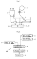
- Fig. 1 is simplified schematic diagram of a consumable electrode gas-shielded pulsed arc welding apparatus (hereinafter, simply 'arc welding apparatus') in one mode for carrying out the present invention. Shown in Fig. 1 are a welding power supply 1 , a welding wire 2 , feed rollers 3 , a contact tip 4 , a workpiece 5 , a shunt 6 for measuring welding current, a weld current detector circuit 31 , and a weld voltage detector circuit 32 .
- Current and voltage from the welding power supply 1 are supplied such as to be applied between the welding wire 2 and the workpiece 5.
- Welding wire 2 is fed out at a prescribed rate by the feed rollers 3 so as to be supplied through the contact tip 4 to the workpiece 5 .
- the ground side of the welding power supply 1 is connected to the weld current detector circuit 31 through the shunt 6 , and is connected directly to the weld voltage detector circuit 32 and a power-on time detector circuit (not shown).
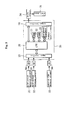
- Fig. 2 is a block diagram showing the configuration of a pulsed arc welding stability assessment apparatus 10 of the present invention.
- the pulsed arc welding stability assessment apparatus 10 comprises a pulse period or base period weld current detector means 11 , a pulse period or base period weld voltage detector means 12 , a pulse period or base period power-on time detector means 13 , a welding stability computer means 14 , a welding stability assessment means 15 , and an alarm means 16 .
- the welding stability computer means 14 Based on detection values detected by the three detection means 11 , 12 , and 13 , the welding stability computer means 14 computes irregularity values separately for each detection value.
- the welding stability assessment means 15 then performs a comparison between these presently computed irregularity values and the same kind of irregularity values detected at the start-of-weld in a known-good pulsed arc weld. An overall assessment of start-of-weld pulsed arc welding stability is then made from the amount of separation of the presently detected irregularity values from the known-good irregularity values. If the overall separation exceeds a reference standard value, a 'not stable' decision is made, and an alarm is issued by the alarm means 16 .
- a controller 26 contains a processing unit 20 (CPU), a memory 21 (ROM), a memory 22 (RAM), an input interface 23 , an output interface 24 , and peripheral equipment 25 (keyboard, monitor, printer, etc.). Also shown are A/D converters (signal converter means) 30 , the welding current detector circuit 31 , the welding voltage detector circuit 32 , the power-on time detector circuit 33 , and a drive circuit 34 for driving the alarm means 16 .
- ROM Read Only Memory 21
- PROM Programs (assessment programs) provided with various processes (included in flow charts to be discussed later), for assessing welding characteristics, so that the proper assessment programs can be executed during operation of the processing unit 20 (CPU).
- Memory 22 (RAM) is for temporary storage of data variables required for execution of the assessment programs.
- the outputs of the detector circuits 31 - 33 pass through the A/D converters 30 to the input interface 23, to be input to the processing unit 20 (CPU). Irregularity values computed by the processing unit 20 (CPU) for welding current, welding voltage and power-on time are each compared against their respective reference standard values. If they fail to match, the drive circuit 34 is activated through the output interface 24, to drive the alarm means 16 , which issues an alarm.
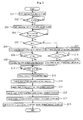
- each of the following are computed, in sequence, as indexes of welding stability irregularity at start-of-weld: ( 1 ) the product of the standard deviations the integrals of pulse current and base current, ( 2 ) the product ofthe standard deviations of pulse time and base time, and ( 3 ) the ratio between the standard deviations of the pulse current and base current (Steps 105 - 107). These indexes are compared with the same indexes for a known-good welding operation, and a welding characteristic pass/fail determination is made based on the amount of separation between the present values and the known-good values (Step 108). If the amount of separation exceeds a reference standard value, a fault signal is output (Step 109).
- the program first starts sampling weld current and weld voltage (Step 201), and then checks for the start of power-on (Step 202). When power-on is detected, measurement of start-of-weld-period weld voltage and weld current begins (Step 203).
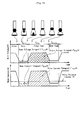
- program execution waits for the end of a no-load voltage time (Step 204), then it determines (Step 205) whether the weld current is equal to or greater than a pulse decision current value I W1 (Fig. 9). If that condition is met, measurement of pulse weld current and pulse time is started (Step 206). If, however, the weld current in Step 205 is less than I W1 , the measurement of base weld current and base time begins (Step 207).
- Step 208 the program checks whether the weld current is less than the pulse current decision value I W1 , and if it is, stops measurement of pulse weld current and pulse power-on time (Step 209), In Step 210, the checks whether the pulse weld current exceeds the pulse decision current level I W1 , If this condition is satisfied, measurement of base welding current and base time is ended (Step 211).
- execution waits for a timer to time-out; after which it computes the start-of-weld-time pulse current integral, pulse time, base current integral, and base time (Steps 213 and 214).
- the program computes the standard deviations of the pulse current integral and base current integral, and the standard deviations of the pulse time and base time (Steps 215 and 216), and goes on to compute the products of the respective standard deviations (Step 217 and 218).
- Fig. 6 shows the flow for the portion of the process that deals with the pulse current integral standard deviation ratio ( ⁇ ( ⁇ I P(n) dt)/S).
- the program starts sampling weld voltage and weld current (Step 301), while checking for the start of power-on (Step 302). Once power-on is detected, the program starts measuring start-of-weld-period weld voltage and weld current (Step 303) while checking for the end of the no-load voltage time (Step 304). When the no-load voltage time ends, the program checks to see if the weld current is at or above the pulse decision current I W1 (Step 305).
- the program starts measuring the pulse weld current and pulse power-on time (Step 306), while checking to see if that current is less than the pulse decision current I W1 (Step 307).
- the program ends the measurement of pulse weld current and pulse power-on time (Step 308).
- the program computes the integral of the pulse current over the start-of-weld time (Step 310) and the standard deviation of that pulse current integral (Step 311). It then divides this pulse current integral standard deviation by the pulse current integral standard deviation for welding performed at the proper voltage, S : ⁇ ( ⁇ I P(n) dt), to thus complete the computation of the pulse current integral standard deviation ratio (Step 312).
- the values of various important characteristics computed as outlined above are each compared to a reference standard value for that characteristic. If a 'fail' decision is made, an alarm is set as described above. When this occurs, operation of the welding line is immediately stopped to prevent welding defects from being passed along to downstream processes. The welding equipment is then checked to isolate fault locations, and make corrections. When this has been accomplished, the welding line is started up again.
- the indexes of welding stability irregularity presented in the above embodiment as indexes to be compared against were (1) the product of the standard deviations the integrals of pulse current and base current, (2) the product of the standard deviations of pulse and base time, and (3) the ratio between the standard deviation of the pulse current integral, and the same standard deviation for a known-good welding operation. It is possible, however, to compute indexes other than the three mentioned above as indicators of irregularity.
- the product (pulse current integral standard deviation) x (base current integral standard deviation) x (pulse period power-on time standard deviation) x (base period power-on time standard deviation) could also be used as an irregularity index.
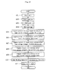
- Fig. 10 is a simplified flow chart, and Figs. 11 and 12 show more detail.
- the assessment program that executes the processes represented by these flow charts is stored in the memory 21 (ROM) of Fig. 3.
- ROM read-only memory
- a sampling process is initiated by starting a weld (Steps 401 and 402) and ends when the weld is ended (Steps 403 and 404).
- each of the following are computed, in sequence, as indexes of welding stability irregularity during steady-state welding: (1) the product of the standard deviations of the integrals of pulse current and base current, (2) the product of the standard deviations of pulse and base time, (3) the product of the standard deviations of the pulse and base voltage integrals, (4) the ratio between the standard deviations of the pulse and base current integrals, and (5) the ratio between the average values of the pulse and base current integrals (Steps 405 - 109). These indexes are compared with the same indexes for a known-good welding operation, and a welding characteristics pass/fail determination is made based on the amount of separation between the computed index values and the known-good index values (Step 410). If the amount of separation exceeds a reference standard value, a fault condition signal is output (Step 411).
- the product of the standard deviations of the pulse current and base current integrals can be expressed as ⁇ ( ⁇ I P(n) dt) x ⁇ ( ⁇ I B(n) dt)
- the product of the standard deviations of the pulse and base time can be expressed as ⁇ T P(n) x ⁇ T B(n)
- the product of the standard deviations of the pulse voltage and base voltage integrals can be expressed as ⁇ ( ⁇ V P(n) dt) x ⁇ ( ⁇ V B(n) dt).
- the program first starts sampling weld current and weld voltage (Step 501), and then checks for the start of power-on (Step 502). When power-on is detected, measurement of weld voltage and weld current during steady state welding begins (Step 503).
- Step 504 the program checks whether the weld current equals or exceeds the pulse decision current value I W1 (Fig. 13). If that condition is met, measurement of pulse weld current, pulse weld voltage, and pulse time is started (Step 505). If, however, the weld current in Step 504 is less than I W1 , the measurement of base weld current, base weld voltage, and base time is started (Step 508). In Step 506, the program checks to see if the weld current is less than the pulse current decision value I W1 , and if it is, ends measurement of pulse weld current, pulse weld voltage, and pulse time (Step 507). In Step 509, the program checks to see if the pulse current exceeds the pulse decision current level I W1 . If that condition is satisfied, measurement of base welding current, base welding voltage, and base time is ended (Step 510).
- execution waits for a timer to time-out; after which it computes the integrals of the pulse current and voltage, the pulse time, the integrals of the base current and voltage, and base time during steady state welding (Steps 512, 513 and 514).
- the program computes the standard deviations of the pulse current integral, the pulse voltage integral, and the pulse time, and the standard deviations of the base current integral, the base voltage integral, and the base time (Steps 515, 516 and 517), and goes on to compute the products of the respective standard deviations (Steps 518, 519 and 520).
- Fig. 12 is the flow for computing the pulse current integral standard deviation ratio ( ⁇ ( ⁇ I P(n) dt)/S ⁇ ) and the pulse current integral average ratio (Ave ( ⁇ I P(n) dt)/S ave ).
- the program starts sampling weld current and weld voltage (Step 601) while checking for the start of power-on (Step 602). Once power-on is detected, the program starts measuring weld voltage and weld current during steady state welding (Step 603).
- the program checks to see if the weld current is at or above the pulse decision current I W1 level (Step 604).
- the program starts measuring the pulse welding current and pulse power-on time (Step 605), while checking to see if that current is less than the pulse decision current I W1 (Step 606).
- the program ends measurement of pulse weld current and pulse time (Step 607).
- the program After waiting for a timer time-out (Step 608), the program computes the pulse current integrals during steady welding (Step 609), and the standard deviation and average value of those pulse current integrals (Steps 610 and 611), and then divides this pulse current integral standard deviation by S : ⁇ ( ⁇ I P(n) dt) (the standard deviation of the integral of the pulse weld current for a weld performed at the optimum voltage), to complete the pulse current integral standard deviation ratio computation (Step 612). Division by S Ave : Ave ( ⁇ I p(n) dt) (the optimum pulse current integral average value) is also performed, to compute a pulse current integral average value ratio (Step 613).
- the values of various important characteristics computed as outlined above are each compared to a reference standard value for that characteristic, and if a 'fail' decision is made, an alarm is set off as described above.
- operation of the welding line is immediately stopped to prevent welding defects from being passed to processes further downstream.
- the welding equipment is then checked to isolate fault locations, and make corrections. When this process is complete, the welding line is started up again.
- the indexes of welding stability irregularity presented in the above embodiment as indexes to be compared against a standard were (1) the product of the standard deviations the integrals of pulse current and base current, (2) the product of the standard deviations of pulse and base time, (3) the product of the standard deviations of the pulse voltage integral and base voltage integral, (4) the ratio between the standard deviation of the pulse current integral and the same standard deviation for a known good weld, and (5) the ratio between the pulse current integral average value and the same average value for a known good weld.
- indexes other than the five mentioned above as indicators of irregularity.
- the product of (pulse current integral standard deviation) x (base current integral standard deviation) x (pulse power-on time standard deviation) x (base power-on time standard deviation) could also be used as an irregularity index.
Landscapes
- Engineering & Computer Science (AREA)
- Theoretical Computer Science (AREA)
- Physics & Mathematics (AREA)
- Plasma & Fusion (AREA)
- Mechanical Engineering (AREA)
- Arc Welding Control (AREA)
- Arc Welding In General (AREA)
Applications Claiming Priority (4)
| Application Number | Priority Date | Filing Date | Title |
|---|---|---|---|
| JP2001129574A JP4642267B2 (ja) | 2001-04-26 | 2001-04-26 | パルスアーク溶接の溶接安定性判定装置 |
| JP2001129551A JP4642266B2 (ja) | 2001-04-26 | 2001-04-26 | パルスアーク溶接の溶接安定性判定装置 |
| JP2001129574 | 2001-04-26 | ||
| JP2001129551 | 2001-04-26 |
Publications (2)
| Publication Number | Publication Date |
|---|---|
| EP1252962A2 true EP1252962A2 (de) | 2002-10-30 |
| EP1252962A3 EP1252962A3 (de) | 2005-01-05 |
Family
ID=26614291
Family Applications (1)
| Application Number | Title | Priority Date | Filing Date |
|---|---|---|---|
| EP02076690A Withdrawn EP1252962A3 (de) | 2001-04-26 | 2002-04-26 | Vorrichtung zur Bewertung der Stabilität des Schweissprozesses beim gepulsten Lichtbogenschweissen |
Country Status (2)
| Country | Link |
|---|---|
| US (1) | US6621049B2 (de) |
| EP (1) | EP1252962A3 (de) |
Cited By (3)
| Publication number | Priority date | Publication date | Assignee | Title |
|---|---|---|---|---|
| WO2004065053A1 (en) * | 2003-01-17 | 2004-08-05 | British Nuclear Fuels Plc | Welding quality control |
| CN102528245A (zh) * | 2010-12-28 | 2012-07-04 | 株式会社大亨 | 电弧焊接方法及电弧焊接系统 |
| CN103357987A (zh) * | 2013-06-28 | 2013-10-23 | 广州中医药大学 | Co2电弧焊短路过渡焊接过程的稳定性自动检测方法 |
Families Citing this family (91)
| Publication number | Priority date | Publication date | Assignee | Title |
|---|---|---|---|---|
| JP3786122B2 (ja) * | 2004-03-26 | 2006-06-14 | 松下電器産業株式会社 | 溶接装置 |
| US7339135B2 (en) * | 2004-06-04 | 2008-03-04 | Illinois Tool Works Inc. | Welding arc stabilization process |
| JP4857534B2 (ja) * | 2004-07-13 | 2012-01-18 | パナソニック株式会社 | アーク溶接ロボット |
| US9000329B2 (en) * | 2004-07-22 | 2015-04-07 | Illinois Tool Works Inc. | Welding arc stabilization process |
| US9937577B2 (en) | 2006-12-20 | 2018-04-10 | Lincoln Global, Inc. | System for a welding sequencer |
| US10994358B2 (en) | 2006-12-20 | 2021-05-04 | Lincoln Global, Inc. | System and method for creating or modifying a welding sequence based on non-real world weld data |
| US9104195B2 (en) | 2006-12-20 | 2015-08-11 | Lincoln Global, Inc. | Welding job sequencer |
| US8049141B2 (en) * | 2007-07-18 | 2011-11-01 | Lincoln Global, Inc. | Method of rating a stick electrode |
| WO2009146359A1 (en) | 2008-05-28 | 2009-12-03 | Illinois Tool Works Inc. | Welding training system |
| US8834168B2 (en) | 2008-08-21 | 2014-09-16 | Lincoln Global, Inc. | System and method providing combined virtual reality arc welding and three-dimensional (3D) viewing |
| US9483959B2 (en) | 2008-08-21 | 2016-11-01 | Lincoln Global, Inc. | Welding simulator |
| US9280913B2 (en) | 2009-07-10 | 2016-03-08 | Lincoln Global, Inc. | Systems and methods providing enhanced education and training in a virtual reality environment |
| US9196169B2 (en) | 2008-08-21 | 2015-11-24 | Lincoln Global, Inc. | Importing and analyzing external data using a virtual reality welding system |
| US9330575B2 (en) | 2008-08-21 | 2016-05-03 | Lincoln Global, Inc. | Tablet-based welding simulator |
| US9318026B2 (en) | 2008-08-21 | 2016-04-19 | Lincoln Global, Inc. | Systems and methods providing an enhanced user experience in a real-time simulated virtual reality welding environment |
| US8911237B2 (en) | 2008-08-21 | 2014-12-16 | Lincoln Global, Inc. | Virtual reality pipe welding simulator and setup |
| US8747116B2 (en) | 2008-08-21 | 2014-06-10 | Lincoln Global, Inc. | System and method providing arc welding training in a real-time simulated virtual reality environment using real-time weld puddle feedback |
| US8851896B2 (en) | 2008-08-21 | 2014-10-07 | Lincoln Global, Inc. | Virtual reality GTAW and pipe welding simulator and setup |
| US8884177B2 (en) | 2009-11-13 | 2014-11-11 | Lincoln Global, Inc. | Systems, methods, and apparatuses for monitoring weld quality |
| US8274013B2 (en) | 2009-03-09 | 2012-09-25 | Lincoln Global, Inc. | System for tracking and analyzing welding activity |
| US10500667B2 (en) * | 2009-04-08 | 2019-12-10 | Panasonic Intellectual Property Management Co., Ltd. | Arc welding method and arc welding apparatus for adjusting a welding current waveform responsive to a setting voltage adjustment |
| WO2010146844A1 (ja) * | 2009-06-19 | 2010-12-23 | パナソニック株式会社 | 消耗電極式アーク溶接方法および消耗電極式アーク溶接装置 |
| US9773429B2 (en) | 2009-07-08 | 2017-09-26 | Lincoln Global, Inc. | System and method for manual welder training |
| US9230449B2 (en) | 2009-07-08 | 2016-01-05 | Lincoln Global, Inc. | Welding training system |
| US9221117B2 (en) | 2009-07-08 | 2015-12-29 | Lincoln Global, Inc. | System for characterizing manual welding operations |
| US9011154B2 (en) | 2009-07-10 | 2015-04-21 | Lincoln Global, Inc. | Virtual welding system |
| US10748447B2 (en) | 2013-05-24 | 2020-08-18 | Lincoln Global, Inc. | Systems and methods providing a computerized eyewear device to aid in welding |
| US8569655B2 (en) | 2009-10-13 | 2013-10-29 | Lincoln Global, Inc. | Welding helmet with integral user interface |
| US8569646B2 (en) | 2009-11-13 | 2013-10-29 | Lincoln Global, Inc. | Systems, methods, and apparatuses for monitoring weld quality |
| US9468988B2 (en) | 2009-11-13 | 2016-10-18 | Lincoln Global, Inc. | Systems, methods, and apparatuses for monitoring weld quality |
| US9101994B2 (en) | 2011-08-10 | 2015-08-11 | Illinois Tool Works Inc. | System and device for welding training |
| US9573215B2 (en) | 2012-02-10 | 2017-02-21 | Illinois Tool Works Inc. | Sound-based weld travel speed sensing system and method |
| US10239145B2 (en) * | 2012-04-03 | 2019-03-26 | Lincoln Global, Inc. | Synchronized magnetic arc steering and welding |
| US9862050B2 (en) * | 2012-04-03 | 2018-01-09 | Lincoln Global, Inc. | Auto steering in a weld joint |
| CN102707158B (zh) * | 2012-06-11 | 2014-06-18 | 西北工业大学 | 基于饱和电抗器稳流电源的真空自耗电弧炉熔滴测试方法 |
| US20160093233A1 (en) | 2012-07-06 | 2016-03-31 | Lincoln Global, Inc. | System for characterizing manual welding operations on pipe and other curved structures |
| US9767712B2 (en) | 2012-07-10 | 2017-09-19 | Lincoln Global, Inc. | Virtual reality pipe welding simulator and setup |
| US9368045B2 (en) | 2012-11-09 | 2016-06-14 | Illinois Tool Works Inc. | System and device for welding training |
| US9583014B2 (en) | 2012-11-09 | 2017-02-28 | Illinois Tool Works Inc. | System and device for welding training |
| US10035211B2 (en) | 2013-03-15 | 2018-07-31 | Lincoln Global, Inc. | Tandem hot-wire systems |
| US9583023B2 (en) | 2013-03-15 | 2017-02-28 | Illinois Tool Works Inc. | Welding torch for a welding training system |
| US10086465B2 (en) | 2013-03-15 | 2018-10-02 | Lincoln Global, Inc. | Tandem hot-wire systems |
| US9713852B2 (en) | 2013-03-15 | 2017-07-25 | Illinois Tool Works Inc. | Welding training systems and devices |
| US9666100B2 (en) | 2013-03-15 | 2017-05-30 | Illinois Tool Works Inc. | Calibration devices for a welding training system |
| US9728103B2 (en) | 2013-03-15 | 2017-08-08 | Illinois Tool Works Inc. | Data storage and analysis for a welding training system |
| US9672757B2 (en) | 2013-03-15 | 2017-06-06 | Illinois Tool Works Inc. | Multi-mode software and method for a welding training system |
| US10930174B2 (en) | 2013-05-24 | 2021-02-23 | Lincoln Global, Inc. | Systems and methods providing a computerized eyewear device to aid in welding |
| US11090753B2 (en) | 2013-06-21 | 2021-08-17 | Illinois Tool Works Inc. | System and method for determining weld travel speed |
| US20150072323A1 (en) | 2013-09-11 | 2015-03-12 | Lincoln Global, Inc. | Learning management system for a real-time simulated virtual reality welding training environment |
| US10083627B2 (en) | 2013-11-05 | 2018-09-25 | Lincoln Global, Inc. | Virtual reality and real welding training system and method |
| US10056010B2 (en) | 2013-12-03 | 2018-08-21 | Illinois Tool Works Inc. | Systems and methods for a weld training system |
| US9589481B2 (en) | 2014-01-07 | 2017-03-07 | Illinois Tool Works Inc. | Welding software for detection and control of devices and for analysis of data |
| US10105782B2 (en) | 2014-01-07 | 2018-10-23 | Illinois Tool Works Inc. | Feedback from a welding torch of a welding system |
| US9757819B2 (en) | 2014-01-07 | 2017-09-12 | Illinois Tool Works Inc. | Calibration tool and method for a welding system |
| US9751149B2 (en) | 2014-01-07 | 2017-09-05 | Illinois Tool Works Inc. | Welding stand for a welding system |
| US9724788B2 (en) | 2014-01-07 | 2017-08-08 | Illinois Tool Works Inc. | Electrical assemblies for a welding system |
| US10170019B2 (en) | 2014-01-07 | 2019-01-01 | Illinois Tool Works Inc. | Feedback from a welding torch of a welding system |
| US10464168B2 (en) | 2014-01-24 | 2019-11-05 | Lincoln Global, Inc. | Method and system for additive manufacturing using high energy source and hot-wire |
| US9836987B2 (en) | 2014-02-14 | 2017-12-05 | Lincoln Global, Inc. | Virtual reality pipe welding simulator and setup |
| CN106233358A (zh) | 2014-06-02 | 2016-12-14 | 林肯环球股份有限公司 | 用于人工焊工培训的系统和方法 |
| US9862049B2 (en) | 2014-06-27 | 2018-01-09 | Illinois Tool Works Inc. | System and method of welding system operator identification |
| US10307853B2 (en) | 2014-06-27 | 2019-06-04 | Illinois Tool Works Inc. | System and method for managing welding data |
| US10665128B2 (en) | 2014-06-27 | 2020-05-26 | Illinois Tool Works Inc. | System and method of monitoring welding information |
| US9937578B2 (en) | 2014-06-27 | 2018-04-10 | Illinois Tool Works Inc. | System and method for remote welding training |
| US9724787B2 (en) | 2014-08-07 | 2017-08-08 | Illinois Tool Works Inc. | System and method of monitoring a welding environment |
| US11014183B2 (en) | 2014-08-07 | 2021-05-25 | Illinois Tool Works Inc. | System and method of marking a welding workpiece |
| US9875665B2 (en) | 2014-08-18 | 2018-01-23 | Illinois Tool Works Inc. | Weld training system and method |
| US11247289B2 (en) | 2014-10-16 | 2022-02-15 | Illinois Tool Works Inc. | Remote power supply parameter adjustment |
| US10239147B2 (en) | 2014-10-16 | 2019-03-26 | Illinois Tool Works Inc. | Sensor-based power controls for a welding system |
| US10417934B2 (en) | 2014-11-05 | 2019-09-17 | Illinois Tool Works Inc. | System and method of reviewing weld data |
| US10204406B2 (en) | 2014-11-05 | 2019-02-12 | Illinois Tool Works Inc. | System and method of controlling welding system camera exposure and marker illumination |
| US10490098B2 (en) | 2014-11-05 | 2019-11-26 | Illinois Tool Works Inc. | System and method of recording multi-run data |
| US10402959B2 (en) | 2014-11-05 | 2019-09-03 | Illinois Tool Works Inc. | System and method of active torch marker control |
| US10373304B2 (en) | 2014-11-05 | 2019-08-06 | Illinois Tool Works Inc. | System and method of arranging welding device markers |
| US10210773B2 (en) | 2014-11-05 | 2019-02-19 | Illinois Tool Works Inc. | System and method for welding torch display |
| US10427239B2 (en) | 2015-04-02 | 2019-10-01 | Illinois Tool Works Inc. | Systems and methods for tracking weld training arc parameters |
| US10657839B2 (en) | 2015-08-12 | 2020-05-19 | Illinois Tool Works Inc. | Stick welding electrode holders with real-time feedback features |
| US10438505B2 (en) | 2015-08-12 | 2019-10-08 | Illinois Tool Works | Welding training system interface |
| US10593230B2 (en) | 2015-08-12 | 2020-03-17 | Illinois Tool Works Inc. | Stick welding electrode holder systems and methods |
| US10373517B2 (en) | 2015-08-12 | 2019-08-06 | Illinois Tool Works Inc. | Simulation stick welding electrode holder systems and methods |
| US10576570B2 (en) | 2015-12-30 | 2020-03-03 | Lincoln Global, Inc. | Weld sequencer part and statistical limits analyzer |
| EP3319066A1 (de) | 2016-11-04 | 2018-05-09 | Lincoln Global, Inc. | Magnetische frequenzwahl für elektromagnetische positionsverfolgung |
| US20180130226A1 (en) | 2016-11-07 | 2018-05-10 | Lincoln Global, Inc. | System and method for calibrating a welding trainer |
| US10913125B2 (en) | 2016-11-07 | 2021-02-09 | Lincoln Global, Inc. | Welding system providing visual and audio cues to a welding helmet with a display |
| US10997872B2 (en) | 2017-06-01 | 2021-05-04 | Lincoln Global, Inc. | Spring-loaded tip assembly to support simulated shielded metal arc welding |
| US11027362B2 (en) | 2017-12-19 | 2021-06-08 | Lincoln Global, Inc. | Systems and methods providing location feedback for additive manufacturing |
| US11557223B2 (en) | 2018-04-19 | 2023-01-17 | Lincoln Global, Inc. | Modular and reconfigurable chassis for simulated welding training |
| US11475792B2 (en) | 2018-04-19 | 2022-10-18 | Lincoln Global, Inc. | Welding simulator with dual-user configuration |
| US11311958B1 (en) * | 2019-05-13 | 2022-04-26 | Airgas, Inc. | Digital welding and cutting efficiency analysis, process evaluation and response feedback system for process optimization |
| US11776423B2 (en) | 2019-07-22 | 2023-10-03 | Illinois Tool Works Inc. | Connection boxes for gas tungsten arc welding training systems |
| US11288978B2 (en) | 2019-07-22 | 2022-03-29 | Illinois Tool Works Inc. | Gas tungsten arc welding training systems |
Family Cites Families (9)
| Publication number | Priority date | Publication date | Assignee | Title |
|---|---|---|---|---|
| DE3545158A1 (de) * | 1985-12-20 | 1987-06-25 | Hahn Ortwin | Adaptives regelungsverfahren fuer schweissprozesse |
| US5221825A (en) * | 1992-06-01 | 1993-06-22 | The United States Of America As Represented By The Secretary Of Commerce | Sensing of gas metal arc welding process characteristics for welding process control |
| US5521354A (en) * | 1994-06-21 | 1996-05-28 | Caterpillar Inc. | Method for arc welding fault detection |
| US5756967A (en) * | 1997-04-09 | 1998-05-26 | The United States Of America As Represented By The Secretary Of Commerce | Sensing ARC welding process characteristics for welding process control |
| JPH10314940A (ja) * | 1997-05-20 | 1998-12-02 | Toyota Motor Corp | アーク溶接機のモニタ方法 |
| JP3898810B2 (ja) * | 1997-10-22 | 2007-03-28 | 中央精機株式会社 | アークスタート時の溶接安定性判定方法及び安定性判定装置 |
| JP3898811B2 (ja) * | 1997-10-22 | 2007-03-28 | 中央精機株式会社 | アーク溶接定常部の溶接安定性判定方法及び安定性判定装置 |
| US6236017B1 (en) * | 1999-07-01 | 2001-05-22 | Bechtel Bwxt Idaho, Llc | Method and apparatus for assessing weld quality |
| US6441342B1 (en) * | 2000-11-20 | 2002-08-27 | Lincoln Global, Inc. | Monitor for electric arc welder |
-
2002
- 2002-04-25 US US10/134,304 patent/US6621049B2/en not_active Expired - Fee Related
- 2002-04-26 EP EP02076690A patent/EP1252962A3/de not_active Withdrawn
Cited By (5)
| Publication number | Priority date | Publication date | Assignee | Title |
|---|---|---|---|---|
| WO2004065053A1 (en) * | 2003-01-17 | 2004-08-05 | British Nuclear Fuels Plc | Welding quality control |
| CN102528245A (zh) * | 2010-12-28 | 2012-07-04 | 株式会社大亨 | 电弧焊接方法及电弧焊接系统 |
| CN102528245B (zh) * | 2010-12-28 | 2016-04-20 | 株式会社大亨 | 电弧焊接方法及电弧焊接系统 |
| CN103357987A (zh) * | 2013-06-28 | 2013-10-23 | 广州中医药大学 | Co2电弧焊短路过渡焊接过程的稳定性自动检测方法 |
| CN103357987B (zh) * | 2013-06-28 | 2014-12-10 | 广州中医药大学 | Co2电弧焊短路过渡焊接过程的稳定性自动检测方法 |
Also Published As
| Publication number | Publication date |
|---|---|
| US6621049B2 (en) | 2003-09-16 |
| US20020170899A1 (en) | 2002-11-21 |
| EP1252962A3 (de) | 2005-01-05 |
Similar Documents
| Publication | Publication Date | Title |
|---|---|---|
| US6621049B2 (en) | Welding stability assessment apparatus for pulsed arc welding | |
| US6703585B2 (en) | Arc welding quality evaluation apparatus | |
| US5349156A (en) | Sensing of gas metal arc welding process characteristics for welding process control | |
| EP2253407B1 (de) | System zur Überwachung von Lichtbogenschweißverfahren und entsprechendes Überwachungsverfahren | |
| US5756967A (en) | Sensing ARC welding process characteristics for welding process control | |
| US6031203A (en) | Method and apparatus for determining stability of arc welding | |
| US6639181B2 (en) | Apparatus and method for assessing electrode tip wear | |
| HU188832B (en) | Method and apparatus for securing the weld quality during operation, for marking the defect spots on piece and for certifying the quality | |
| JP3898811B2 (ja) | アーク溶接定常部の溶接安定性判定方法及び安定性判定装置 | |
| JP3898810B2 (ja) | アークスタート時の溶接安定性判定方法及び安定性判定装置 | |
| Barborak et al. | " Through-arc" process monitoring: techniques for control of automated gas metal arc welding | |
| JP4642267B2 (ja) | パルスアーク溶接の溶接安定性判定装置 | |
| JP4642266B2 (ja) | パルスアーク溶接の溶接安定性判定装置 | |
| JP2000024779A (ja) | 溶接チップの寿命評価方法および装置 | |
| JP3898812B2 (ja) | アーク溶接終端処理部の溶接安定性判定方法及び安定性判定装置 | |
| JPS61199578A (ja) | ア−ク溶接ロボツトにおける溶接監視装置 | |
| JP4534770B2 (ja) | 溶接監視装置と溶接監視方法 | |
| JP3396602B2 (ja) | 溶接品質監視方法および装置 | |
| CN112439976B (zh) | 利用类焊接热输入进行目视测量的检测方法及焊接方法 | |
| JP3697359B2 (ja) | アーク溶接安定性判定方法及び装置 | |
| JP2002001534A (ja) | アーク溶接モニタリング方法とその装置 | |
| KR100270098B1 (ko) | 용접품질 판정장치 및 방법 | |
| JP2025138574A (ja) | 溶接品質の評価方法、溶接品質評価装置及びそれを備えた溶接システム | |
| JP3906559B2 (ja) | 溶接品質判定方法及び装置 | |
| JP2001198681A (ja) | インバータ式抵抗溶接の非破壊検査装置及び方法 |
Legal Events
| Date | Code | Title | Description |
|---|---|---|---|
| PUAI | Public reference made under article 153(3) epc to a published international application that has entered the european phase |
Free format text: ORIGINAL CODE: 0009012 |
|
| AK | Designated contracting states |
Kind code of ref document: A2 Designated state(s): AT BE CH CY DE DK ES FI FR GB GR IE IT LI LU MC NL PT SE TR |
|
| AX | Request for extension of the european patent |
Free format text: AL;LT;LV;MK;RO;SI |
|
| PUAL | Search report despatched |
Free format text: ORIGINAL CODE: 0009013 |
|
| AK | Designated contracting states |
Kind code of ref document: A3 Designated state(s): AT BE CH CY DE DK ES FI FR GB GR IE IT LI LU MC NL PT SE TR |
|
| AX | Request for extension of the european patent |
Extension state: AL LT LV MK RO SI |
|
| 17P | Request for examination filed |
Effective date: 20050311 |
|
| AKX | Designation fees paid |
Designated state(s): DE |
|
| 17Q | First examination report despatched |
Effective date: 20070320 |
|
| GRAP | Despatch of communication of intention to grant a patent |
Free format text: ORIGINAL CODE: EPIDOSNIGR1 |
|
| STAA | Information on the status of an ep patent application or granted ep patent |
Free format text: STATUS: THE APPLICATION IS DEEMED TO BE WITHDRAWN |
|
| 18D | Application deemed to be withdrawn |
Effective date: 20111006 |