EP1253005A2 - Modulare Vorrichtung zum Herstellen von Beuteln - Google Patents
Modulare Vorrichtung zum Herstellen von Beuteln Download PDFInfo
- Publication number
- EP1253005A2 EP1253005A2 EP02250575A EP02250575A EP1253005A2 EP 1253005 A2 EP1253005 A2 EP 1253005A2 EP 02250575 A EP02250575 A EP 02250575A EP 02250575 A EP02250575 A EP 02250575A EP 1253005 A2 EP1253005 A2 EP 1253005A2
- Authority
- EP
- European Patent Office
- Prior art keywords
- station
- module
- pouch machine
- pouch
- machine
- Prior art date
- Legal status (The legal status is an assumption and is not a legal conclusion. Google has not performed a legal analysis and makes no representation as to the accuracy of the status listed.)
- Withdrawn
Links
Images


Classifications
-
- B—PERFORMING OPERATIONS; TRANSPORTING
- B31—MAKING ARTICLES OF PAPER, CARDBOARD OR MATERIAL WORKED IN A MANNER ANALOGOUS TO PAPER; WORKING PAPER, CARDBOARD OR MATERIAL WORKED IN A MANNER ANALOGOUS TO PAPER
- B31B—MAKING CONTAINERS OF PAPER, CARDBOARD OR MATERIAL WORKED IN A MANNER ANALOGOUS TO PAPER
- B31B70/00—Making flexible containers, e.g. envelopes or bags
- B31B70/006—Controlling; Regulating; Measuring; Safety measures
-
- B—PERFORMING OPERATIONS; TRANSPORTING
- B31—MAKING ARTICLES OF PAPER, CARDBOARD OR MATERIAL WORKED IN A MANNER ANALOGOUS TO PAPER; WORKING PAPER, CARDBOARD OR MATERIAL WORKED IN A MANNER ANALOGOUS TO PAPER
- B31B—MAKING CONTAINERS OF PAPER, CARDBOARD OR MATERIAL WORKED IN A MANNER ANALOGOUS TO PAPER
- B31B2155/00—Flexible containers made from webs
- B31B2155/001—Flexible containers made from webs by folding webs longitudinally
- B31B2155/0014—Flexible containers made from webs by folding webs longitudinally having their openings facing transversally to the direction of movement
-
- B—PERFORMING OPERATIONS; TRANSPORTING
- B31—MAKING ARTICLES OF PAPER, CARDBOARD OR MATERIAL WORKED IN A MANNER ANALOGOUS TO PAPER; WORKING PAPER, CARDBOARD OR MATERIAL WORKED IN A MANNER ANALOGOUS TO PAPER
- B31B—MAKING CONTAINERS OF PAPER, CARDBOARD OR MATERIAL WORKED IN A MANNER ANALOGOUS TO PAPER
- B31B2160/00—Shape of flexible containers
- B31B2160/10—Shape of flexible containers rectangular and flat, i.e. without structural provision for thickness of contents
-
- B—PERFORMING OPERATIONS; TRANSPORTING
- B31—MAKING ARTICLES OF PAPER, CARDBOARD OR MATERIAL WORKED IN A MANNER ANALOGOUS TO PAPER; WORKING PAPER, CARDBOARD OR MATERIAL WORKED IN A MANNER ANALOGOUS TO PAPER
- B31B—MAKING CONTAINERS OF PAPER, CARDBOARD OR MATERIAL WORKED IN A MANNER ANALOGOUS TO PAPER
- B31B70/00—Making flexible containers, e.g. envelopes or bags
- B31B70/005—Making flexible containers, e.g. envelopes or bags involving a particular layout of the machinery or relative arrangement of its subunits
-
- B—PERFORMING OPERATIONS; TRANSPORTING
- B31—MAKING ARTICLES OF PAPER, CARDBOARD OR MATERIAL WORKED IN A MANNER ANALOGOUS TO PAPER; WORKING PAPER, CARDBOARD OR MATERIAL WORKED IN A MANNER ANALOGOUS TO PAPER
- B31B—MAKING CONTAINERS OF PAPER, CARDBOARD OR MATERIAL WORKED IN A MANNER ANALOGOUS TO PAPER
- B31B70/00—Making flexible containers, e.g. envelopes or bags
- B31B70/74—Auxiliary operations
- B31B70/81—Forming or attaching accessories, e.g. opening devices, closures or tear strings
- B31B70/813—Applying closures
- B31B70/8131—Making bags having interengaging closure elements
- B31B70/8132—Applying the closure elements in the machine direction
Definitions
- the present invention relates generally to the art of bag making. More specifically, it relates to pouch-type bag making.
- Pouch machines may have continuous or intermittent motion, and have a generally horizontal or vertical machines film path. In either case a continuous web of material or film is converted into a series of individual pouches. Generally, the continuous film is folded in half over a plow or forming shoulder. The folded web is transported through at least one cross-sealer, which has seal bars in the cross-machine direction, to form cross seals, thus creating a strip of pouches interconnected by transverse seals (and open opposite the fold). A cut-off unit separates the continuous film into individual pouches by cutting each cross-seal. Individual pouches are subsequently filled and sealed at a separate machine.
- Prior art intermittent motion pouch machines alternately advance the film, and then the various processing stations process the film when it is stationary (the dwell time).
- Examples of such pouch machines include U.S. Patent No. 5,181,365 and 6,195,967 (hereby incorporated by reference).
- Pouch machines perform a number of processes in addition to the sealing and cutting described above that form the pouch, such as forming a zipper seal (or weld) on a film, forming a long seal (machine direction) on the film, and applying a "slider" closure on the film.
- One or more of these processes, along with feeding/folding the film, forming cross-seals, and separating adjacent pouches are performed in succession, and, depending on what process are performed, any of a variety of pouch style may be made.
- the machinery performing the processes are housed in a single structure (called a cab or cabinet).
- a single controller controls the entire process and all of the needed machinery.
- the controller is typically housed in a separate structure.
- Such a pouch machine has one common electrical control cabinet housing the complete electrical requirements for the complete specialized machine line. This makes for an inflexible, limited product range machine, and its expensive to change product styles.
- a pouch manufacturer desires to make a particular style pouch
- the machinery needed to perform the required processes is determined, and a specialized machine, including a controller, is built. If the pouch manufacturer desires to make a different style pouch a new machine must be built, or the existing machine must be disassembled, and then rebuilt with the appropriate machinery and controls.
- Another type of prior art pouch machine provides for modules which each house machinery for a specific task, rather than a single cab.
- a single central controller is provided to control each of the various modules. Changing pouch styles requires changing modules, and rewiring of the controller, and possibly a redesign of the controller so that it can control the new modules.
- Pouch machines are typically 30 or more feet in length due to the great number of processes that have to be done to the web.
- the film or web is drawn through the machine by a single drawroll assembly.
- the drawroll is registered to a registration mark on a film.
- An example of such a prior art machine is found in US Patent No. RE 35,067, hereby incorporated by reference.
- Some prior art machines have dual drawroll systems, such as that described in US Patent No. 5,086,964 (hereby incorporated by reference). Such a system uses one drawroll for registration and the other drawroll for advancing the web and setting web tension between the drawrolls.
- prior art pouch machines provide that the machinery or tooling that performs the process on the web (cross sealing, punching, die cutting, etc.) are each on an independent carriage that is moved to the position of the stopped web to accurately register the process to the web, film, mark, seal, etc.
- a pouch machine that does not require processing devices to be moved along the machine direction for proper registration is desirable.
- Pouch machines in the prior art includes web guides.
- Such guides were developed for use with continuous motion machines and the guides were separate from the rolls drawing or driving the film or web.
- the web guides were needed because the web often tracked toward one side of the machine or the other. This may be caused by mis-alignment of drawrolls, sections of the machine being out of proper alignment with each other, material which is thicker on one edge of the web than the opposite edge or stretched material. Whatever the cause, it is important to keep the web tracking properly through the machine.
- Figure 3 shows such a prior art web guide system that includes guide roller or rollers 320 moving in a lateral and angular direction. This movement steers the web laterally into the entering span 321 of the drawrolls 309.
- the guide is mounted on slides or bearings 322, with a point of rotation 323. While this technology may be better than other prior art web guides, it was developed for a moving web, it has several shortcomings when applied to an intermittent machine such as a pouch machine such as locating the nips (from guide rolls 320) in or near the longitudinal sealer section, the web is not guided properly in intermittent motion, and it requires additional framework and additional rack and rail length is required.
- a pouch machine includes a controller and first and second modules. Each module has a converting station and the electrical equipment needed to operate the station. The controller controls the converting stations. The first module further has an operating parameter input connected to the controller and an operating parameter output. The second module has an operating parameter input, connected to the operating parameter output.
- a pouch machine has a plurality of modules.
- Each module includes a converting station and is electrically self-contained.
- the modules are configured in a daisy-chain. Successive modules receive operating parameters from the preceding module.
- a method of making a pouch machine includes selecting two modules. Each module has a converting station operatively connected to a central controller. An operating parameter output is provided from the first module to the second module.
- a third module including a converting station, may be connected to the second module, wherein operating parameters are received by the third module in one embodiment.
- the first module have an infeed station
- the second and third modules have converting stations that are one (not necessarily the same one) of the group consisting of a zipper sealer station, a long sealer station, a cross sealer station, a cross seal extension station, and a slider station
- a fourth modules may have a cut-off station.
- a common user interface for a central controller is provided in another alternative.
- a pouch machine includes two processing zones. Each has a first station along a film path, a registration sensor along the film path, and a drawroll. Each drawroll is responsive to the respective registration sensor.
- the sensor is an optical sensor that detects print registration marks in one alternative.
- the processing stations are at fixed locations in another embodiment.
- Accumulators are included in each processing zone, and the machine includes a third processing zone that does not have a draw roll in various embodiments.
- a pouch machine includes a plurality of processing devices.
- An edge sensor senses the edge of the film.
- a draw roll assembly is mounted on a moveable frame, and is angled in response to the location of the sensed edge. Multiple such assemblies may be included on a single machine.
- One aspect of the invention relates to a modular design of a pouch machine converting line.
- the machine is comprised of several free standing, mechanically and electrically self-contained modular sections.
- Electrical self-contained includes a module that has the electrical equipment needed to operate the module, although not necessarily the controller.
- Each section is designed to plug in and produce a unique pouch product.
- This fast, flexible, "plug and play", building block approach allows for the converting of multiple pouch style products from a single base machine. It also increases the versatility of the base machine to economically adapt to different products in changing markets.
- the invention eliminates the common main cabinet by providing individual cabinets containing all the electrical that is required for that specific modular section of machine.
- the overall machine line is then controlled through fiber optic wires between modules and to the PC based operator interface - the controls are daisy chained.
- Registration sensor includes a sensor that detects a seal or registration mark on a film, bag or pouch, and may include circuitry, digital and/or analog and hardware and/or software that provides a signal indicating the location of the registration mark, seal, or pouch.
- This reduces or eliminates the need for processing devices to be mounted on carriages. This may be combined with the modularity aspect, or implemented separately.
- Another aspect of the invention provides for having the drawrolls cooperate with an edge sensor, such that the draw rolls are both drawing the film and guiding the film.
- the drawrolls are mounted on a moving frame, and are moved to a desired angle to guide the film in a desired direction (in response to the edge sensor). This aspect may be combined with the other aspects, or implemented by itself.
- a pouch machine 100 constructed in accordance with the present invention is shown, and includes mechanical and electrical modularity. While a particular configuration is shown, the invention contemplates other configurations may be readily obtained using a arrangement of self-controlled modules.
- Module includes a housing in which a processing station is disposed.
- Self-contained modules includes modules having electrical and mechanical equipment that form a processing station disposed within the module, wherein a controller controls the operation of the processing station by providing operating parameters. Feedback may be provided to the controller from the module.
- Controller includes a device that controls a processing station, and can include analog and/or digital circuitry, and be implemented with hardware and/or software.
- Converting or processing station includes the machinery that performs a process on the film, such as sealing, folding, transporting, cutting, forming zippers or sliders, etc.
- Pouch machine 100 includes seven modules: an infeed module 1, a zipper sealer module 2, a long sealer module 3, a cross sealer module 4, a cross seal extension module 5, a slider module 6, and a cut-off module 7. Some of the modules, such as 4, 6 and 7, include drawrolls (10, 11 and 12).
- Infeed station includes a processing station that receives a film and feeds it to subsequent processing stations, it may include machinery for folding the film.
- Zipper sealer station includes a processing station that welds or forms a zipper onto a pouch, usually in the machine direction.
- Long sealer station includes a processing station that forms a machine direction seal.
- Cross sealer station includes a processing station that forms a cross-seal, such as the seals separating successive pouches.
- Cross seal extension station includes a processing station that forms cross seals over an extended length.
- Slider station includes a processing station applies a "slider" onto a pouch, usually in the machine direction.
- Cut-off station includes a processing station that cuts the film, such as that used to separate adjacent pouches.
- Each module has all the mechanical features and machinery required to accomplish it's specific task, along with a specific electrical enclosure to provide power to it's machinery. Power is preferably provided from one module to the next so that they have interconnected power, or it maybe provided individually to each module.
- Interconnected power includes modules that share a common power source, such as a power line connecting one module to another.
- a common PC based operator interface 8 will provide the operating parameters and is part of a central controller that controls each of the modules.
- Common user interface includes a user interface that allows the user to input information for some or all of the processing stations in a pouch machine.
- PC based includes a user interface using personal computer type processor, screen etc.
- Each module provides the operating parameters to the succeeding module on an operating parameter output, and likewise each succeeding module receives the operating parameters on an operating parameter input.
- the first module receives operating parameters from the central controller and the last module can be connected back to the controller.
- Operating parameter output includes providing machine operating parameters as an output.
- Operating parameter input includes receiving operating parameters as an input for controlling a processing station.
- Operating parameters includes parameters used by the controller to control a processing station, such as movement instructions, timing information, speed, distance, processes needed, temperature of seals, dwell time, etc.
- the intermediate modules both send and receive operating parameters.
- Intermediate modules includes modules other than the first and last modules.
- the modules are connected in a daisy-chain configuration.
- Disisy-chain includes connecting each module (other than the first) to a preceding module, such that operating parameters are passed from module to module, and can include a connection from the last module to the controller, and controller to the first module.
- the connection and communications protocol may be SERCOS fiber optic, conventional hard wire communication lines, such as RS 485, wireless protocol, TCP/IP (internet) or other types.
- Pouch machine 100 in the configuration of figure 1, has all modules and is capable of producing the largest variety of finished pouch products which include a 3-side seal pouch, a 3-side seal pouch with "press-to-close” zipper, a 3-side seal pouch with “slider” zipper, a stand-up pouch, a stand-up pouch with “press-to-close” zipper, and a stand-up pouch with “slider” zipper.
- the modules that would produce a 3-side seal pouch includes modules 1, 3, 4 & 7.
- the 3-side seal pouch with "press-to-close” zipper may be made with modules 1,2,3,4,5, & 7.
- the 3-side seal pouch with "slider” zipper may be made with modules 1,2,3,4,6 & 7.
- Stand-up pouches may be made with modules 1,3,4 & 7.
- the stand-up pouch with "press-to-close” zipper may be made with modules 1,2,3,4,5 & 7.
- the stand-up pouch with slider zipper may be made with modules 1,2,3,4,6 & 7.
- a pouch manufacture desires to make a 3-side seal pouch he need only purchase modules 1, 3, 4 and 7. Should he desire later to enter the 3-side seal with a press to close zipper market, he need only buy the additional modules.
- Other advantages of this invention include the machine footprint being less wide compared to prior art units having a free standing main electrical enclosure, standard modules can be manufactured cost effectively, and customers do not need to know exactly which pouch market they are targeting because they can buy a basic machine and add modules to it as their needs change, cost effectively, and field conversions are cost effective.
- Drawroll includes a roll or plurality of driven rolls that drive the film, pouch, or bag.
- Processing zones 18, 19 and 20 may be processing zones such as those shown in Figure 1 (the processing machinery is omitted in Figure 2). Each zone is provided with a drawroll (21, 31, and 41) and an optical sensor or photo-eye (22, 32 and 42).
- Optical sensor includes a sensor such as photo cell that detects an optical mark, seal, bag or pouch.
- the controller uses the detection from the photo-eye to control each draw roll to register the web to the processing device.
- Each photo eye detects the presence of a printed registration mark (or seal etc.) on web or film 20.
- Each drawroll is responsive to the optical sensor or registration sensor, and advances web 20 to a registered stop position determined by the respective photo eye within the respective zone. Responsive to a registration sensor, as used herein, includes processing the film such that the process is registered to the mark, seal, or pouch.
- Accumulator includes rolls or other devices that adjust the film path length.
- Processing devices need not be mounted on carriages to register to the film or mark, and are at fixed locations (they still move toward or way from the web or be positioned manually).
- Processing station at a fixed location includes a station that does not move automatically along the film path to register the station to the film, mark, seal, pouch or bag.
- Film path extending from one zone to a second other zone includes the film passing from the first zone, and either directly to the second zone, or first passing through a third zone, and then passing to the second zone.
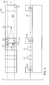
- Figure 4 shows a machine 400, including drawrolls 401 and 403 (they may be drawrolls 21, 31 or 41 from Figure 2). Processing stations 413 and 415 may be any of the processing stations described above. Drawroll 403 acts as a web guide (drawroll 401 can do so as well, although the detail is omitted in Figure 4.)
- a web or film 405 passes through machine 400 and edges 407 of web 405 are accurately held in a desired location.
- Web 405 is guided such that wrinkling is eliminated or reduced of the web is done without the system continuously "hunting" for the web edge.
- the web guiding system steers the web during the during the draw or feed cycle of the web and includes edge sensors 417 and 419.
- Sensors 417 and 419 sense the position of one edge or both edges 407 of web 405 depending on whether the web is edge-guided or center-guided, and send a signal to a prime mover 420, whether electric motor, hydraulic or pneumatic cylinder, electro-mechanical actuator or other device and angular re-position the movable drawroll assembly.
- Drawroll assembly includes the structure on which a drawroll is (or plurality of drawrolls are) mounted.
- Edge sensor 417, 419 are preferably mounted downstream of the movable drawroll in a fixed position while the machine is running.
- Edge sensor includes a sensor such as an optical sensor that locates the edge of a film or web, or locates a mark on the web from which the location of the edge of the web may be inferred.
- the invention may be implemented with existing center-guiding technology, and the sensors can be mounted so that both sensors are movable toward and away from each other automatically as the web or sheet width changes.
- electronic circuitry sends a signal to prime mover 420 of the guiding system. This signal controls the direction of movement of prime mover 420 depending on the direction of movement of the web or sheet.
- intermittently driven drawrolls 403 are mounted on a sub-frame or drawroll frame which in turn is mounted on shafts and bearings 422 so as to move in an arc motion.
- This arc motion has a point of rotation 424 located several inches upstream of the drawrolls.
- the prime mover As the prime mover is actuated, it will move the drawrolls in an arc motion transverse to the web travel, or be angled in either direction away from the machine direction. (Angled in either direction away from machine direction, as used herein, includes angled to the left or right (in a horizontal plane) sufficient to steer the web.)
Landscapes
- Making Paper Articles (AREA)
Applications Claiming Priority (4)
| Application Number | Priority Date | Filing Date | Title |
|---|---|---|---|
| US840370 | 1992-02-24 | ||
| US83905801A | 2001-04-20 | 2001-04-20 | |
| US839058 | 2001-04-20 | ||
| US09/840,370 US20020155936A1 (en) | 2001-04-23 | 2001-04-23 | Modular pouch machine |
Publications (2)
| Publication Number | Publication Date |
|---|---|
| EP1253005A2 true EP1253005A2 (de) | 2002-10-30 |
| EP1253005A3 EP1253005A3 (de) | 2003-04-09 |
Family
ID=27126077
Family Applications (1)
| Application Number | Title | Priority Date | Filing Date |
|---|---|---|---|
| EP02250575A Withdrawn EP1253005A3 (de) | 2001-04-20 | 2002-01-28 | Modulare Vorrichtung zum Herstellen von Beuteln |
Country Status (1)
| Country | Link |
|---|---|
| EP (1) | EP1253005A3 (de) |
Cited By (3)
| Publication number | Priority date | Publication date | Assignee | Title |
|---|---|---|---|---|
| EP1702849A3 (de) * | 2005-03-16 | 2008-04-30 | Illinois Tool Works Inc. | Anpassung des stoßweise bewegten Verschlussbandes mit der kontinuierlich bewegten Folie |
| DE102007059665A1 (de) * | 2007-12-10 | 2009-06-18 | Anton Debatin GmbH Werk für werbende Verpackung | Verfahren und Vorrichtung zur Herstellung eines Kunststoff-Beutels |
| WO2009121836A1 (de) * | 2008-04-03 | 2009-10-08 | Windmöller & Hölscher Kg | Vorrichtung und verfahren zur herstellung von säcken |
Citations (4)
| Publication number | Priority date | Publication date | Assignee | Title |
|---|---|---|---|---|
| US35067A (en) | 1862-04-29 | Improvement in revolving fire-arms | ||
| US5086964A (en) | 1988-07-29 | 1992-02-11 | Amplas, Inc. | Dual drive web feed apparatus and method |
| US5181365A (en) | 1991-12-09 | 1993-01-26 | Minnesota Mining And Manufacturing Company | Method and apparatus for forming individual pouches from a continuous web and packaging a product in the individual pouches |
| US6195967B1 (en) | 1998-11-03 | 2001-03-06 | Klockner Bartelt, Inc. | Packaging machine having continuous and intermittent modes |
Family Cites Families (3)
| Publication number | Priority date | Publication date | Assignee | Title |
|---|---|---|---|---|
| CH628855A5 (fr) * | 1978-04-03 | 1982-03-31 | Fobelmac Sprl | Procede pour acheminer et traiter ou travailler en continu une bande souple pour produire des documents et installation pour sa mise en oeuvre. |
| CA2142480A1 (en) * | 1994-02-17 | 1995-08-18 | Donn A. Hartman | Modular pouch making machine |
| DE29503390U1 (de) * | 1994-12-03 | 1995-04-27 | Ostma Maschinenbau GmbH, 53909 Zülpich | Maschinenaggregat für die Herstellung von Faltschachteln |
-
2002
- 2002-01-28 EP EP02250575A patent/EP1253005A3/de not_active Withdrawn
Patent Citations (4)
| Publication number | Priority date | Publication date | Assignee | Title |
|---|---|---|---|---|
| US35067A (en) | 1862-04-29 | Improvement in revolving fire-arms | ||
| US5086964A (en) | 1988-07-29 | 1992-02-11 | Amplas, Inc. | Dual drive web feed apparatus and method |
| US5181365A (en) | 1991-12-09 | 1993-01-26 | Minnesota Mining And Manufacturing Company | Method and apparatus for forming individual pouches from a continuous web and packaging a product in the individual pouches |
| US6195967B1 (en) | 1998-11-03 | 2001-03-06 | Klockner Bartelt, Inc. | Packaging machine having continuous and intermittent modes |
Cited By (7)
| Publication number | Priority date | Publication date | Assignee | Title |
|---|---|---|---|---|
| EP1702849A3 (de) * | 2005-03-16 | 2008-04-30 | Illinois Tool Works Inc. | Anpassung des stoßweise bewegten Verschlussbandes mit der kontinuierlich bewegten Folie |
| US7513858B2 (en) | 2005-03-16 | 2009-04-07 | Illinois Tool Works Inc. | Registration of intermittently moved fastener tape with continuously moving web |
| EP2145825A3 (de) * | 2005-03-16 | 2011-05-18 | Illinois Tool Works Inc. | Anpassung des stoßweise bewegten Verschlussbandes mit der kontinuirlich bewegten Folie |
| DE102007059665A1 (de) * | 2007-12-10 | 2009-06-18 | Anton Debatin GmbH Werk für werbende Verpackung | Verfahren und Vorrichtung zur Herstellung eines Kunststoff-Beutels |
| WO2009121836A1 (de) * | 2008-04-03 | 2009-10-08 | Windmöller & Hölscher Kg | Vorrichtung und verfahren zur herstellung von säcken |
| US8597167B2 (en) | 2008-04-03 | 2013-12-03 | Windmoeller & Hoelscher Kg | Device and method for producing bags |
| CN101983125B (zh) * | 2008-04-03 | 2014-12-31 | 温德莫勒及霍尔希尔公司 | 用于生产袋子的装置和方法 |
Also Published As
| Publication number | Publication date |
|---|---|
| EP1253005A3 (de) | 2003-04-09 |
Similar Documents
| Publication | Publication Date | Title |
|---|---|---|
| CA2379006C (en) | Modular pouch machine | |
| US6247293B1 (en) | Modular packaging machine with web tension control | |
| US6675552B2 (en) | Method and device for producing bags with three sealed edges and welded-in closing seal | |
| US5072571A (en) | Zippered film plural sheet strip guide system and method for zippered film for form, fill and seal package making machines | |
| EP0999139A2 (de) | Siegelvorrichtung für Verpackungsmaschine | |
| JP2000296644A (ja) | ブランクに印刷を施す方法と装置 | |
| US9061783B2 (en) | Fin seal registration in manufacture of reclosable packages | |
| EP1253005A2 (de) | Modulare Vorrichtung zum Herstellen von Beuteln | |
| GB9708541D0 (en) | Manufacture of plastic bags | |
| CN113910682A (zh) | 一种中分制袋机制作四边封包装袋的方法 | |
| AU712551B2 (en) | Packaging machine with a stripping device | |
| EP2497716B1 (de) | Vertikale Flow-Wrap-Verpackungsmaschine mit Folienzuführungsmittel | |
| US20070091171A1 (en) | Shuttle Pouch Machine | |
| JP2608174B2 (ja) | ヒートシール装置 | |
| JP3283030B2 (ja) | 製袋機におけるサイドシール方法及び装置 | |
| GB1475007A (en) | Edge capping and web folding attachment for bag forming machines | |
| JPH08169406A (ja) | 真空包装装置 | |
| US12420513B2 (en) | Machine for production of stand up pouches | |
| CN220281882U (zh) | 一种包装机的单皮带包装袋输送机构 | |
| CN217144960U (zh) | 口罩定位熔接成形机 | |
| WO1998040202A1 (en) | Packaging machine | |
| GB2138353A (en) | Production of bags from an elongate web | |
| CN215512837U (zh) | 一种卫星式印刷机印后冷却纠偏一体式牵引装置 | |
| JP2002059911A (ja) | 製袋充填包装機の捺印位置合わせ装置 | |
| NL1020510C2 (nl) | Vorm-, vul- en sluitmachine met baankantvolger. |
Legal Events
| Date | Code | Title | Description |
|---|---|---|---|
| PUAI | Public reference made under article 153(3) epc to a published international application that has entered the european phase |
Free format text: ORIGINAL CODE: 0009012 |
|
| AK | Designated contracting states |
Kind code of ref document: A2 Designated state(s): AT BE CH CY DE DK ES FI FR GB GR IE IT LI LU MC NL PT SE TR |
|
| AX | Request for extension of the european patent |
Free format text: AL;LT;LV;MK;RO;SI |
|
| PUAL | Search report despatched |
Free format text: ORIGINAL CODE: 0009013 |
|
| AK | Designated contracting states |
Kind code of ref document: A3 Designated state(s): AT BE CH CY DE DK ES FI FR GB GR IE IT LI LU MC NL PT SE TR Designated state(s): AT BE CH CY DE DK ES FI FR GB GR IE IT LI LU MC NL PT SE TR |
|
| AX | Request for extension of the european patent |
Extension state: AL LT LV MK RO SI |
|
| 17P | Request for examination filed |
Effective date: 20030912 |
|
| AKX | Designation fees paid |
Designated state(s): BE ES FR GB IT |
|
| REG | Reference to a national code |
Ref country code: DE Ref legal event code: 8566 |
|
| RBV | Designated contracting states (corrected) |
Designated state(s): BE ES FR GB IT |
|
| 17Q | First examination report despatched |
Effective date: 20051205 |
|
| GRAP | Despatch of communication of intention to grant a patent |
Free format text: ORIGINAL CODE: EPIDOSNIGR1 |
|
| RIN1 | Information on inventor provided before grant (corrected) |
Inventor name: GARY SARGIN Inventor name: GERARD R WINIECKI Inventor name: MARK KRUEGER Inventor name: DAVID THOMAS Inventor name: SCOTT A MATTILA Inventor name: GAYLORD GUILETTE Inventor name: RANDY C WIED |
|
| STAA | Information on the status of an ep patent application or granted ep patent |
Free format text: STATUS: THE APPLICATION IS DEEMED TO BE WITHDRAWN |
|
| 18D | Application deemed to be withdrawn |
Effective date: 20070526 |