EP1253033A2 - Climatiseur de véhicule et procédé de contrôle d'un climatiseur de véhicule - Google Patents
Climatiseur de véhicule et procédé de contrôle d'un climatiseur de véhicule Download PDFInfo
- Publication number
- EP1253033A2 EP1253033A2 EP02009438A EP02009438A EP1253033A2 EP 1253033 A2 EP1253033 A2 EP 1253033A2 EP 02009438 A EP02009438 A EP 02009438A EP 02009438 A EP02009438 A EP 02009438A EP 1253033 A2 EP1253033 A2 EP 1253033A2
- Authority
- EP
- European Patent Office
- Prior art keywords
- air conditioner
- pressure difference
- force
- compressor
- engine
- Prior art date
- Legal status (The legal status is an assumption and is not a legal conclusion. Google has not performed a legal analysis and makes no representation as to the accuracy of the status listed.)
- Withdrawn
Links
Images


Classifications
-
- F—MECHANICAL ENGINEERING; LIGHTING; HEATING; WEAPONS; BLASTING
- F02—COMBUSTION ENGINES; HOT-GAS OR COMBUSTION-PRODUCT ENGINE PLANTS
- F02D—CONTROLLING COMBUSTION ENGINES
- F02D41/00—Electrical control of supply of combustible mixture or its constituents
- F02D41/02—Circuit arrangements for generating control signals
- F02D41/14—Introducing closed-loop corrections
- F02D41/16—Introducing closed-loop corrections for idling
-
- B—PERFORMING OPERATIONS; TRANSPORTING
- B60—VEHICLES IN GENERAL
- B60H—ARRANGEMENTS OF HEATING, COOLING, VENTILATING OR OTHER AIR-TREATING DEVICES SPECIALLY ADAPTED FOR PASSENGER OR GOODS SPACES OF VEHICLES
- B60H1/00—Heating, cooling or ventilating devices
- B60H1/32—Cooling devices
- B60H1/3204—Cooling devices using compression
- B60H1/3205—Control means therefor
- B60H1/322—Control means therefor for improving the stop or idling operation of the engine
-
- B—PERFORMING OPERATIONS; TRANSPORTING
- B60—VEHICLES IN GENERAL
- B60H—ARRANGEMENTS OF HEATING, COOLING, VENTILATING OR OTHER AIR-TREATING DEVICES SPECIALLY ADAPTED FOR PASSENGER OR GOODS SPACES OF VEHICLES
- B60H1/00—Heating, cooling or ventilating devices
- B60H1/32—Cooling devices
- B60H2001/3236—Cooling devices information from a variable is obtained
- B60H2001/3255—Cooling devices information from a variable is obtained related to temperature
-
- B—PERFORMING OPERATIONS; TRANSPORTING
- B60—VEHICLES IN GENERAL
- B60H—ARRANGEMENTS OF HEATING, COOLING, VENTILATING OR OTHER AIR-TREATING DEVICES SPECIALLY ADAPTED FOR PASSENGER OR GOODS SPACES OF VEHICLES
- B60H1/00—Heating, cooling or ventilating devices
- B60H1/32—Cooling devices
- B60H2001/3269—Cooling devices output of a control signal
- B60H2001/327—Cooling devices output of a control signal related to a compressing unit
- B60H2001/3275—Cooling devices output of a control signal related to a compressing unit to control the volume of a compressor
Definitions
- the present invention relates to an apparatus and method for controlling a vehicle air conditioner having a variable displacement compressor.
- the prior art idle-up control is always executed when the engine is idling and the compressor is activated. Accordingly, the idle speed fluctuates whenever the compressor is activated or deactivated. This increases the vibrations and noise of the vehicle.
- the increased amount of the idle speed during the idle-up control is determined presuming that the torque required to drive the compressor is maximal, that is, the displacement of the compressor is maximal. Accordingly, if, for example, the displacement of the compressor is small and the torque required to drive the compressor is low, the idle speed is increased in an unnecessary manner. This is not desirable from the viewpoint of fuel efficiency.
- the present invention provides a vehicle air conditioner including a refrigerant circuit that incorporates a variable displacement compressor driven by an engine of the vehicle.
- the air conditioner includes a control valve for varying the displacement of the compressor.
- An air conditioner control unit controls the control valve.
- the control valve includes a pressure sensing mechanism having a valve body and a pressure sensing member connected to the valve body and moved in accordance with a pressure difference between two pressure monitoring points located along the refrigerant circuit. The pressure difference corresponds to the displacement of the compressor and alters the moved amount of the pressure sensing member.
- a pressure difference adjusting actuator is controlled by the air conditioner control unit.
- the pressure difference adjusting actuator applies a force, which counters the movement of the pressure sensing member, to the valve body to move the valve body and alter the moved amount of the pressure sensing member.
- the pressure difference adjusting actuator further adjusting the force applied to the valve body to alter the moved amount of the pressure sensing member and vary the displacement of the compressor.
- the air conditioner control unit changes the force of the pressure difference adjusting actuator applied to the valve body to adjust the pressure difference and vary the displacement of the compressor. The changes in force when the engine is running at an idle speed is more gradual than when the engine is running at a speed other than the idle speed.
- a further perspective of the present invention is a method for controlling a vehicle air conditioner including a refrigerant circuit that incorporates a variable displacement compressor driven by an engine of the vehicle, a pressure sensing mechanism, and a pressure difference adjusting actuator.
- the pressure sensing mechanism has a valve body and a pressure sensing member, which is connected to the valve body and moved in accordance with the pressure difference between two pressure monitoring points located along the refrigerant circuit.
- the pressure difference adjusting actuator applies a force, which counters the movement of the pressure sensing member, to the valve body to move the valve body, and changes the force applied to the valve body to alter the moved amount of the pressure sensing member, adjust the pressure difference, and vary the displacement.
- the method includes changing the force of the pressure difference adjusting actuator applied to the valve body to adjust the pressure difference and vary the displacement of the compressor when the engine is running at an idle speed.
- the changes in force when the engine is running at the idle speed are more gradual than when the engine is running at a speed other than the idle speed.
- an engine E which is a drive source of a vehicle, includes an idle speed control valve (ISCV) 65.
- ISCV idle speed control valve
- the ISCV 65 functions to adjust the amount of the intake air drawn into the engine E.
- the engine E has an output shaft, which is connected to a swash plate type variable displacement compressor 40 by means of a power transmission mechanism PT.
- the compressor 40 is included in a refrigerant circuit (refrigerating cycle).
- the vehicle is provided with an engine ECU 71, which controls the ISCV 65, and an air conditioner (A/C) ECU 72.
- the engine ECU 71 and the A/C ECU 72 communicate with each other.
- the engine ECU 71 functions to control the idle speed and alter a target idle speed.
- the A/C ECU 72 functions to control the compressor 40 and also functions to change the target idle speed.
- the engine ECU 71 is connected to a vehicle state detector 73.
- the vehicle state detector 73 includes a vehicle velocity sensor 74, an engine speed sensor 75, and a throttle position sensor 76.
- the vehicle velocity sensor 74 detects the traveling velocity of the vehicle.
- the engine speed sensor 75 detects the engine speed.
- the throttle position sensor 76 detects the angle of a throttle (not shown) that changes in accordance with the depressed amount of an acceleration pedal (not shown).
- the A/C ECU 72 is connected to an A/C state detector 77.
- the A/C state detector 77 includes an A/C switch 79, a temperature setting device 80, and a temperature sensor 81, which generate signals provided to the A/C ECU 72.
- the A/C switch 79 is used to activate and deactivate the air conditioner and generates a signal indicating whether the air conditioner is activated.
- the temperature setting device 80 is used to set a target temperature Te set of the passenger compartment (not shown) and generates a signal indicating the target temperature Te set .
- the temperature sensor 81 detects the actual temperature Te t of the passenger compartment and generates a signal indicating the detected temperature Te t .
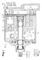
- the compressor 40 has a housing 11.
- a crank chamber 12 is defined in the housing 11.
- a drive shaft 13 is rotatably arranged in the crank chamber 12.
- the power transmission mechanism PT does not have a clutch mechanism.
- the power of the engine E is constantly transmitted to the compressor 40.
- the power transmission mechanism PT may be provided with a clutch (e.g., electromagnetic clutch) that disconnects the compressor 40 from the engine E.
- a lug plate 14 is fixed to the drive shaft 13 in the crank chamber 12 and rotates integrally with the drive shaft 13.
- a swash plate 15 is accommodated in the crank chamber 12. The swash plate 15 is supported so that it inclines as it moves along the drive shaft 13.
- a hinge mechanism 16 is arranged between the lug plate 14 and the swash plate 15. The hinge mechanism 16 enables the swash plate 15 to incline while rotating integrally with the lug plate 14 and the drive shaft 13.
- a plurality of cylinder bores 11a (only one shown in Fig. 1) are formed in the housing 11.
- a piston 17 is reciprocally retained in each cylinder bore 11a.
- Each piston 17 is engaged with the peripheral portion of the swash plate 15 by a pair of shoes 18. As the drive shaft 13 rotates, the shoes 18 convert the rotating motion of the swash plate 15 to the reciprocating motion of the piston 17.
- a valve plate 19 is arranged at the rear (toward the right as viewed in Fig. 1) of the cylinder bores 11a.
- a compression chamber 20 is defined in each cylinder bore 11a between the associated piston 17 and the valve plate 19.
- a suction chamber 21 and a discharge chamber 22 are defined in the rear portion of the housing 11.
- refrigerant gas is drawn from the suction chamber 21 into the associated compression chamber 20 through a suction port 23 and a suction valve 24, which are formed in the valve plate 19.
- the refrigerant gas drawn into the compression chamber 20 is compressed to a predetermined pressure as the piston 17 moves from the bottom dead center position to the top dead center position.
- the refrigerant gas is discharged into the discharge chamber 22 through a discharge port 25 and a discharge valve 26, which are formed in the valve plate 19.
- a bleeding passage 27, a first gas supplying passage 28a, and a second gas supplying passage 28b are provided in the housing 11.
- the bleeding passage 27 connects the crank chamber 12 to the suction chamber 21.
- the first and second gas supplying passages 28a, 28b connect the discharge chamber to the crank chamber 12.
- a control valve CV is arranged between the first and second gas supplying passages 28a, 28b in the housing 11.
- An opened amount of the control valve CV is varied to adjust the amount of high pressure discharge gas sent into the crank chamber 12 through the first and second gas supplying passages 28a, 28b and the amount of gas sent out from crank chamber 12 through the bleeding passage 27.
- the control valve CV controls the balance between the gas amount sent into the crank chamber 12 and the gas amount sent out from the crank chamber 12 to determine the pressure of the crank chamber 12.
- the pressure of the crank chamber 12 is changed to adjust the difference between the pressure of the crank chamber 12 and the pressure of the compression chambers 20, which act on the pistons 17. This changes the inclination of the swash plate 15, alters the stroke of the pistons 17, and varies the displacement of the compressor 40.
- Fig. 1 show the swash plate 15 arranged at a maximum inclination position. In this state, the swash plate 15 is in contact with the lug plate 14. This restricts further inclination of the swash plate 15.
- the solid lines in Fig. 1 show the swash plate 15 arranged at a minimum inclination position. In this state, the swash plate 15 is inclined relatively to a plane perpendicular to the axis of the drive shaft 13 at an angle that is slightly greater than zero.
- a refrigerant circuit (refrigerating cycle) of the vehicle air conditioner is formed by the compressor 40 and an external refrigerant circuit 30.
- the external refrigerant circuit 30 includes a condenser 31, an expansion valve 32, and an evaporator 33.
- a shutting valve 34 is arranged between the discharge chamber 22 of the compressor 40 and the condenser 31.
- the shutting valve 34 shuts the passage between the discharge chamber 22 and the condenser 31 when the pressure of the discharge chamber 22 is lower than a predetermined value to stop circulating refrigerant through the external refrigerant circuit 30.
- the shutting valve 34 may be a differential valve that detects the difference between the pressure at its upstream side and the pressure at its downstream side and functions in accordance with the pressure difference.
- the shutting valve 34 may be an electromagnetic valve controlled by the A/C ECU 72 in accordance with the detection of a discharge pressure sensor (not shown).
- the shutting valve 34 may be a valve that closes mechanically when the swash plate 15 is arranged at the minimum inclination position.
- the refrigerant circuit includes a first pressure monitoring point P1 and a second pressure monitoring point P2.
- the first pressure monitoring point P1 is located in the discharge chamber P1.
- the second pressure monitoring point P2 is arranged downstream of the first pressure monitoring point P1, or between the shutting valve 34 and the condenser 31.
- the difference between the pressure PdH at the first pressure monitoring point P1 and the pressure PdL at the second pressure monitoring point P2 reflects the amount of refrigerant flowing through the refrigerant circuit.
- the first pressure monitoring point P1 and the control valve CV are connected by a first pressure detection passage 35.
- the second pressure monitoring point P2 and the control valve CV are connected by a second pressure detection passage 36 (Fig. 2).
- the control valve CV has a valve housing 41 in which a valve chamber 42, a communication passage 43, and a pressure sensing chamber 44 are defined.
- a rod 45 which is movable in its axial direction, is arranged in the valve chamber 42 and the communication passage 43.
- the top portion of the rod 45 which is inserted in the communication passage 43, disconnects the communication passage 43 from the pressure sensing chamber 44.
- the valve chamber 42 is connected to the discharge chamber 22 by the first gas supplying passage 28a.
- the communication passage 43 is connected to the crank chamber 12 through the second gas supplying passage 28b.
- the valve chamber 42 and the communication passage 43 are located between the first and second gas supplying passages 28a, 28b.
- a valve body 46 which is defined on the middle portion of the rod 45, is arranged in the valve chamber 42.
- a valve seat 47 is defined at the boundary between the valve chamber 42 and the communication passage 43.
- the communication passage 43 functions as a valve hole.
- a pressure sensing member, or bellows 48 is accommodated in the pressure sensing chamber 44.
- the top of the bellows 48 is fixed to the valve housing 41.
- the bottom of the bellows 48 is fixed to the top portion of the rod 45.
- the internal space of the bellows 48 defines a first pressure chamber 49 and the external space of the bellows 48 defines a second pressure chamber 50.
- the pressure PdH at the first pressure monitoring point P1 is communicated to the first pressure chamber 49 via the first pressure detection passage 35.
- the pressure PdL at the second pressure monitoring point P2 is communicated to the second pressure chamber 50 via the second pressure detection passage 36.
- the valve body 46, the bellows 48, and the pressure sensing chamber 44 form a pressure sensing mechanism.
- An electromagnetic actuator (pressure difference adjusting actuator) 51 is arranged in the lower portion of the valve housing 41.
- a cylindrical sleeve 52 which has a closed bottom, extends through the center of the electromagnetic actuator 51.
- a fixed core 53 is fitted in the sleeve 52.
- a plunger chamber 54 is defined in the sleeve 52 below the fixed core 53.
- a plunger 56 which is made of a magnetic material and axially movable, is retained in the plunger chamber 54.
- a guide bore 57 extends axially through the center of the fixed core 53.
- the lower portion of the rod 45 which is axially movable, is arranged in the guide bore 57.
- the bottom end of the rod 45 is engaged with the top end of the plunger 56 in the plunger chamber 54.
- a plunger spring 60 is retained in the plunger chamber 54 between the bottom surface of the sleeve 52 and the plunger 56.
- the plunger spring 60 urges the plunger 56 toward the fixed core 53.
- the elastic force of the bellows 48 urges the rod 45 toward the plunger 56. Accordingly, the plunger 56 and the rod 45 always move upward and downward integrally.
- the force of the bellows 48 is stronger than the force of the plunger spring 60.
- a coil 61 is wound around the fixed core 53 and the plunger 56 on the peripheral surface of the sleeve 52.
- the A/C ECU 72 instructs a drive circuit 78 to supply the coil 61 with power in accordance with the information provided from the A/C state detector 77.
- An electromagnetic force (electromagnetic attracting force), which corresponds to the amount of power supplied to the coil 61 by the drive circuit 78, is produced between the plunger 56 and the fixed core 53.
- the electromagnetic force attracts the plunger 56 toward the fixed core 53.
- the voltage applied to the coil 61 is adjusted to control the amount of power supplied to the coil 61.
- Pulse width control (pulse width modulation) is executed to adjust the applied voltage.
- the shutting valve 34 closes since the pressure of the discharge chamber 22 is lower than the predetermined value. This stops circulating refrigerant through the external refrigerant circuit 30. In this state, the compressor 40 continuously compresses refrigerant gas but the air conditioner does not cool the passenger compartment. In other words, the compressor 40 is substantially deactivated.
- the inclination of the swash plate 15 is not zero when arranged at the minimum inclination position.
- refrigerant gas is drawn into the compression chambers 20 from the suction chamber 21, compressed, and then discharged from the compression chambers 20 into the discharge chamber 22.
- an internal refrigerant circuit extending from the discharge chamber 22, through the first and second gas supplying passages 28a, 28b, the crank chamber 12, the bleeding passage 27, the suction chamber 21, the compression chambers 20, and back to the suction chamber 21 is formed in the compressor 40.
- Refrigerant and lubricating oil which is suspended in the refrigerant, circulates through the internal refrigerant circuit.
- lubricating oil remains in the compressor 40 and continues to lubricate moving parts (e.g., the swash plate 15 and the shoes 18) in a satisfactory state.
- the drive circuit 78 controls a duty ratio Dt to adjust the power supplied to the coil 61.
- the duty ratio Dt is variable within a predetermined range.
- an upward electromagnetic urging force is added to the force of the plunger spring 60.
- the upward urging force overcomes the downward urging force of the bellows 48 and moves the rod 45 upward.
- the electromagnetic force which is added to the upward urging force of the plunger spring 60, counters the downward urging force that is produced by the pressure difference ⁇ Pd between the first and second pressure monitoring points (PdH-PdL) and added to the force of the bellows 48.
- valve body 46 of the rod 45 is positioned relative to the valve seat 47 at a location where the upper and lower urging forces are balanced. This adjusts the displacement of the compressor 40. In this state, the compressor 40 is activated and the compressed refrigerant gas is sent to the external refrigerant circuit 30.
- the flow rate of the refrigerant in the refrigerant circuit decreases the downward urging force produced by the pressure difference ⁇ Pd.
- the rod 45 (valve body 46) moves upward, decreases the opened amount of the communication passage 43, and decreases the pressure of the crank chamber 12.
- This moves the swash plate 15 toward the maximum inclination position and increases the displacement of the compressor 40.
- the increase in the displacement of the compressor 40 increases the flow rate of the refrigerant in the refrigerant circuit.
- the pressure difference ⁇ Pd increases.
- control valve CV automatically moves the rod 45 (valve body 46) when the pressure difference ⁇ Pd fluctuates to maintain the pressure difference ⁇ Pd at its target value, which is determined by the duty ratio Dt of the coil 61.
- the pressure difference ⁇ Pd may be adjusted by an external device that controls the duty ratio Dt of the coil 61.
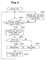
- the engine ECU 71 executes the process illustrated in Fig. 3.
- step S301 the engine ECU 71 determines whether the conditions for executing an idling state intake air amount control (hereafter simply referred to as idling control) are satisfied by referring to the information provided by the vehicle state detector 73. For example, if the ECU 71 receives information indicating that the vehicle velocity is zero and that the throttle is completely closed from the vehicle state detector 73, the ECU 71 determines that the conditions for executing the idling control are satisfied.
- idling control idling state intake air amount control
- step S301 If the engine ECU 71 determines that the conditions for executing the idling control are not satisfied in step S301, the ECU 71 proceeds to step S302 and informs the A/C ECU 72 that the idling control execution conditions are not satisfied. The engine ECU 71 then returns to step S301 from step S302 and repetitively monitors the idling control execution conditions.
- step S301 the ECU 71 determines that the conditions for executing the idling control are satisfied in step S301, the ECU 71 proceeds to step S303 and informs the A/C ECU 72 that the idling control execution conditions are satisfied. The engine ECU 71 then proceeds from step S303 to step S304 and determines whether the A/C ECU 72 is generating an idle-up request. If the engine ECU 71 determines that an idle-up request is not being generated in step S304, the engine ECU 71 proceeds to step S305 and sets a target idle speed Ne set at a predetermined first value Ne set1 (e.g., 700rpm).
- Ne set1 e.g. 700rpm
- step S306 sets the target idle speed Ne set at a predetermined second value Ne set2 (e.g., 900rpm), which is greater than the first value Ne set1 .
- Ne set2 e.g., 900rpm
- the engine ECU 71 proceeds from step S305 or step S306 to step S307 and executes idling control, which is known in the art. More specifically, the engine ECU 71 operates the ISCV 65 to increase or decrease the idle state intake air amount while referring to the information of the engine speed Ne from the vehicle state detector 73 so that the engine speed Ne matches the target idle speed Ne set1 .
- the A/C ECU 72 In a state in which the engine E is running normally and the engine ECU 71 informs the A/C ECU 72 that the idling control execution conditions are not satisfied, the A/C ECU 72 continues to execute the process illustrated in Fig. 4 until informed that the idling control execution conditions are satisfied.
- step S101 the A/C ECU 72 performs various initializations in accordance with an initialization program. For example, the A/C ECU 72 sets the duty ratio Dt of the control valve CV at an initial value of zero (i.e., the coil 61 not being supplied with power).
- step S102 the A/C ECU 72 checks whether the A/C switch 79 is turned on. If the A/C switch 79 is turned on, the A/C ECU 72 proceeds to step S103 and sets the duty ratio Dt of the control valve CV at the minimum duty ratio Dt min .
- step S104 the A/C ECU 72 determines whether the detected temperature Te t of the temperature sensor 81 is greater than the target temperature Te set set by the temperature setting device 80. If the detected temperature Te t is not greater than the target temperature Te set , the A/C ECU 72 proceeds to step S105 and determines whether the detected temperature Te t is less than the target temperature Te set . If the detected temperature Te t is not less than the target temperature Te set , this indicates that the detected temperature Te t is equal to the target temperature Te set . In such state, there is no need to change the duty ratio Dt. Thus, the A/C ECU 72 proceeds to step S108 without instructing the drive circuit 78 to change the duty ratio Dt.
- step S104 determines that the detected temperature Te t is greater than the target temperature Te set in step S104, this indicates that the passenger compartment is hot and that the compressor 40 must operate under a large cooling load.
- the A/C ECU 72 thus proceeds to step S106 and increases the duty ratio Dt by a predetermined grading amount ⁇ D and instructs the drive circuit 78 to change the duty ratio Dt to the corrected value (Dt+ ⁇ D). This slightly decreases the opened amount of the control valve CV and increases the displacement of the compressor 40. As a result, the amount of heat exchanged by the evaporator 33 increases and the temperature Te 1 decreases.
- step S105 If the A/C ECU 72 determines that the detected temperature Te t is less than the target temperature Te set in step S105, this indicates that the temperature of the passenger compartment does not have to be decreased and that the cooling load applied to the compressor 40 is small.
- the A/C ECU 72 thus proceeds to step S107 and decreases the duty ratio Dt by a predetermined grading amount ⁇ D and instructs the drive circuit 78 to change the duty ratio Dt to the corrected value (Dt- ⁇ D).
- step S108 the A/C ECU 72 determines whether the A/C switch 79 is turned off. If the A/C switch 79 is not turned off, the A/C ECU 72 returns to step S104 and repeats the subsequent steps. If the A/C switch 79 is turned off, the A/C ECU 72 proceeds to step S101. This sets the duty ratio Dt of the power supplied to the coil 61 of the control valve CV at zero. In such state, the compressor 40 is substantially deactivated.
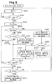
- the engine ECU 71 informs the A/C ECU 72 that the idling control execution conditions are satisfied when the engine E is running, the A/C ECU 72 continues to execute the process illustrated in Fig. 5 until informed that the idling control execution conditions are not satisfied.
- the engine ECU 71 uses the first value Ne set1 as the target idle speed Ne set when executing the idling control of the engine E.
- step S201 the A/C ECU 72 performs initialization in the same manner as in step S101 of Fig. 4.
- step S202 the A/C ECU 79 checks whether the A/C switch 79 is turned on or off in the same manner as step S102. Further, when the A/C switch 79 is turned on, the A/C ECU 72 proceeds to step S203 and sets the duty ratio Dt of the control valve CV at the minimum duty ratio Dt min in the same manner as in step S103. Then, in steps S204 and S205, the A/C ECU 72 determines the relationship between the detected temperature Te t and the target temperature Te set in the same manner as in steps S104 and S105.
- step S204 the A/C ECU 72 determines that the detected temperature Te t is greater than the target temperature Te set in step S204. If the A/C ECU 72 determines that the detected temperature Te t is greater than the target temperature Te set in step S204, the A/C ECU 72 proceeds to step S206 and increases the duty ratio Dt by a predetermined grading amount ⁇ D/10 and instructs the drive circuit 78 to change the duty ratio Dt to the corrected value (Dt+ ⁇ D/10). If the A/C ECU 72 determines that the detected temperature Te t is less than the target temperature Te set in step S205, the A/C ECU 72 proceeds to step S207 and decreases the duty ratio Dt by the predetermined grading amount ⁇ D/10 and instructs the drive circuit 78 to change the duty ratio Dt to the corrected value (Dt- ⁇ D/10).
- the grading amount used to change the duty ratio Dt when the engine E is idling is less than that used to change the duty ratio Dt when the engine E is running normally (in the preferred embodiment, one tenth).
- the grading amount ⁇ D/10 is set so that the duty ratio Dt increases from the minimum value Dt min to the maximum value of the duty ratio range within about 5 to 15 seconds.
- the duty ratio Dt is gradually changed by a smaller amount when the engine E is idling. In other words, more time is required to change the duty ratio Dt to a certain value.
- the displacement of the compressor 40 varies in a gradual manner, and the torque required to drive the compressor 40 changes in a gradual manner.
- the engine ECU 71 responds properly to fluctuations of the engine speed Ne, which is caused by changes in the torque of the compressor 40, when performing idling control. This prevents the difference between the engine speed E and the target idle speed Ne set from becoming large and destabilizing the idling state of the engine E.
- the A/C ECU 72 proceeds from step S206 to step S208 to determine whether the duty ratio Dt of the control valve CV is greater than a predetermined threshold value Dt ref .
- the threshold value Dt ref corresponds to the pressure difference ⁇ Pd required for the compressor 40 to obtain its maximum displacement in a state in which the engine speed Ne is equal to the first target idle speed Ne set1 .
- the necessary flow rate of the refrigerant in the refrigerant circuit may be obtained by increasing the displacement of the compressor 40 even if the engine speed Ne is equal to the first target idle speed Ne set1 .
- the refrigerant flow rate may be increased without increasing the engine speed Ne when the engine E is idling.
- the A/C ECU 72 thus informs the engine ECU 71 that there is no need to execute the idle-up control.
- the engine ECU 71 performs idling control using the first target idle speed Ne set1 (refer to step S305 of Fig. 3).
- step S208 When the duty ratio Dt is greater than the predetermined threshold value Dt ref in step S208, the necessary flow rate of the refrigerant in the refrigerant circuit cannot be obtained even if the displacement of the compressor 40 is increased as long as the engine speed Ne is equal to the first target idle speed Ne set1 .
- step S210 the A/C ECU 72 thus requests the engine ECU 71 to execute the idle-up control. Hence, the engine ECU 71 performs idling control using the second target idle speed Ne set2 (refer to step S306 of Fig. 3).
- the A/C ECU 72 proceeds from step S205, S207, S209, or S210 to step S211 to determine whether the A/C switch 79 is turned off. If the A/C switch 79 is not turned off, the A/C ECU 72 returns to step S204 and changes the duty ratio Dt based on the relationship between the target temperature Te set and the detected temperature Te t .
- step S211 if the A/C ECU 72 determines that the A/C switch 79 is turned off, the A/C ECU 72 proceeds to step S212 and determines whether the duty ratio Dt is greater than the minimum duty ratio Dt min . If the duty ratio Dt is not greater than the minimum duty ratio Dt min , the A/C ECU 72 returns to step S201 to set the duty ratio Dt to zero and substantially deactivate the compressor 40.
- the torque required to drive the compressor 40 is small as long as the duty ratio Dt is less than or equal to the minimum duty ratio Dt min . Thus, deactivation of the compressor 40 subtly affects the engine speed Ne since the torque required to drive the compressor 40 is minimized.
- step S212 the A/C ECU 72 proceeds to step S213.
- step S213 the A/C ECU 72 decreases the duty ratio Dt by the predetermined grading amount ⁇ D/10 and instructs the drive circuit 78 to change the duty ratio Dt to the corrected value (Dt- ⁇ D/10).
- the A/C ECU 72 therefore gradually decreases the duty ratio Dt by repeating step S213 even if the duty ratio Dt is greater than the minimum duty ratio Dt min by a significant amount.
- This gradually decreases the displacement of the compressor 40 and gradually decreases the torque required to drive the compressor 40.
- the gradual torque decrease enables the engine ECU 71 to stabilize the idle speed as it executes the idling control. This prevents a sudden torque decrease from increasing the engine speed Ne in a sudden manner (a state referred to as racing) when the engine E is idling.
- the preferred embodiment has the advantages described below.
- the displacement of the compressor 40 may not vary gradually even when the target suction value is changed. For example, if the amount of heat exchanged by the evaporator 33 were to be large and the actual suction pressure were to be significantly greater than the target suction pressure, the displacement of the compressor 40 would become maximal soon after the A/C switch 79 is turned on even if the pressure difference adjusting actuator gradually changes the force applied to the pressure sensing mechanism. Thus, to prevent the engine E from stalling due to a sudden increase in the torque required to drive the compressor 40 when the engine E is idling, idle-up control must be executed when the A/C switch 79 is turned on.
- the A/C ECU 72 does not use the suction pressure, which is affected by the amount of heat exchanged by the evaporator 33, to control the displacement of the compressor.
- the A/C ECU 72 feedback controls the displacement of the compressor 40 based on the pressure difference ⁇ Pd between the two pressure monitoring points P1, P2 that reflect the flow rate of the refrigerant in the refrigerant circuit. Accordingly, the duty ratio Dt of the control valve CV is gradually changed to gradually vary the displacement of the compressor regardless of the amount of heat exchanged by the evaporator 33.
- the idle speed of the engine E may also be decreased with such structure. In other words, the target idle speed Ne set may easily be set at a low value.
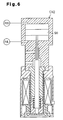
- the compressor 40 may employ a control valve CV2, which incorporates a movable partition 90 to serve as the pressure sensing member in lieu of the bellows 48.
- a control valve CV2 which incorporates a movable partition 90 to serve as the pressure sensing member in lieu of the bellows 48.
- the pressure PdH at the first pressure monitoring point P1 is applied to one side of the partition 90
- the pressure PdL at the second pressure monitoring point P2 is applied to the other side of the partition 90.
- the partition 90 moves in accordance with the difference between the pressures PdH and PdL and functions in accordance with the bellows 48 of the preferred embodiment.
- the grading amount of the duty ratio in steps S206 and S207 may be equal to the grading value ⁇ D of the duty ratio Dt used in steps S106 and S107 (refer to Fig. 4) when the engine E is running normally.
- a step for delaying the time from when the A/C ECU 72 performs step S206 to when the A/C ECU 72 performs step S207 is included between the steps S206 and S207. This changes the duty ratio Dt more gradually in comparison to when the engine W is running normally.
- a clutch mechanism electrically controlled by an external device to selectively connect and disconnect the drive source (engine E) and the compressor 40, such as an electromagnetic clutch, may be used as the power transmission mechanism PT.
- the first pressure monitoring point P1 may be located in a suction pressure region defined between the evaporator 33 and the suction chamber 21, and the second pressure monitoring point P2 may be located in the same suction pressure region downstream of the first pressure monitoring point P1.
- the first pressure monitoring point P1 may be located in a discharge pressure region defined between the discharge chamber 22 and the condenser 31, and the second pressure monitoring point P2 may be located in a suction pressure region.
- the first pressure monitoring point P1 may be located in the discharge pressure region, and the second pressure monitoring point P2 may be located in the crank chamber 12.
- the second pressure monitoring point P2 may be located in the crank chamber 12, and the first pressure monitoring point P1 may be located in the section pressure region.
- one of the pressure monitoring points P1 and P2 may be located in the crank chamber 12, which defines an intermediate pressure region.
- the communication passage 43 may be connected to the discharge chamber 22 through the first gas supplying passage 28a, and the valve chamber 42 may be connected to the crank chamber 12 through the second gas supplying passage 28b. This decreases the pressure difference between the communication passage 43 and the second pressure chamber 50, which is adjacent to the communication passage 43. As a result, pressure leakage between the communication passage 43 and the second pressure chamber 50 is reduced and the compressor displacement is controlled with high accuracy.
- a control valve connected to the bleeding passage 27 instead of the gas supplying passages 28a, 28b may be employed in lieu of the control valve to adjust the opening of the bleeding passage 27 and control the pressure of the crank chamber 12.
- variable displacement compressor 40 may be of a type that uses a wobble type swash plate.
- a vehicle air conditioner including a refrigerant circuit that incorporates a variable displacement compressor (40) driven by an engine (E) of the vehicle.
- the air conditioner includes a control valve (CV) for varying the displacement of the compressor and an ECU (72) for controlling the control valve.
- the control valve has a bellows (48; 90), a valve body (46), and a coil (61).
- the ECU varies the displacement of the compressor by energizing the coil to apply a force, which counters the movement of the bellows, to the valve body to move the valve body. This alters the moved amount of the bellows.
- the air conditioner control unit gradually changes the force applied to the valve body by the coil to adjust the pressure difference and vary the displacement of the compressor when the engine is running at an idle speed.
Landscapes
- Engineering & Computer Science (AREA)
- Mechanical Engineering (AREA)
- Physics & Mathematics (AREA)
- Thermal Sciences (AREA)
- Chemical & Material Sciences (AREA)
- Combustion & Propulsion (AREA)
- General Engineering & Computer Science (AREA)
- Air-Conditioning For Vehicles (AREA)
- Compressors, Vaccum Pumps And Other Relevant Systems (AREA)
- Control Of Positive-Displacement Pumps (AREA)
- Control Of Vehicle Engines Or Engines For Specific Uses (AREA)
- Electrical Control Of Air Or Fuel Supplied To Internal-Combustion Engine (AREA)
Applications Claiming Priority (2)
| Application Number | Priority Date | Filing Date | Title |
|---|---|---|---|
| JP2001131522 | 2001-04-27 | ||
| JP2001131522A JP2002327686A (ja) | 2001-04-27 | 2001-04-27 | 車両用空調装置及び内燃機関のアイドル回転速度制御装置 |
Publications (2)
| Publication Number | Publication Date |
|---|---|
| EP1253033A2 true EP1253033A2 (fr) | 2002-10-30 |
| EP1253033A3 EP1253033A3 (fr) | 2003-10-22 |
Family
ID=18979697
Family Applications (1)
| Application Number | Title | Priority Date | Filing Date |
|---|---|---|---|
| EP02009438A Withdrawn EP1253033A3 (fr) | 2001-04-27 | 2002-04-25 | Climatiseur de véhicule et procédé de contrôle d'un climatiseur de véhicule |
Country Status (5)
| Country | Link |
|---|---|
| US (1) | US6505473B2 (fr) |
| EP (1) | EP1253033A3 (fr) |
| JP (1) | JP2002327686A (fr) |
| KR (1) | KR100455240B1 (fr) |
| CN (1) | CN1251897C (fr) |
Families Citing this family (15)
| Publication number | Priority date | Publication date | Assignee | Title |
|---|---|---|---|---|
| JP2002276557A (ja) * | 2001-03-22 | 2002-09-25 | Toyota Industries Corp | 圧縮機トルク算出方法及び空調装置並びにエンジン制御装置 |
| JP4107141B2 (ja) * | 2003-02-21 | 2008-06-25 | 株式会社デンソー | リミッタ装置 |
| JP4118181B2 (ja) * | 2003-03-28 | 2008-07-16 | サンデン株式会社 | 可変容量斜板式圧縮機の制御弁 |
| KR100973442B1 (ko) * | 2003-08-30 | 2010-08-02 | 한라공조주식회사 | 자동차의 성에 재발 방지방법 |
| JP2006029144A (ja) * | 2004-07-13 | 2006-02-02 | Sanden Corp | 可変容量斜板式圧縮機の容量制御弁 |
| JP2006029150A (ja) * | 2004-07-13 | 2006-02-02 | Sanden Corp | クラッチレス可変容量斜板式圧縮機の容量制御弁 |
| EP1650067B1 (fr) | 2004-10-21 | 2008-07-16 | Halla Climate Control Corporation | Procédé de régulation d'une installation de climatisation pour véhicule |
| EP1696041A1 (fr) * | 2005-02-28 | 2006-08-30 | Fujikoki Corporation | Méthode pour fabriquer un corps rassemblé de plusieurs membres, méthode de fabrication de soupape de commande électromagnétique et soupape de commande pour compresseur variable de capacité |
| JP2009036182A (ja) * | 2007-08-03 | 2009-02-19 | Fuji Koki Corp | 可変容量型圧縮機用制御弁 |
| ES2381258T3 (es) * | 2008-01-24 | 2012-05-24 | Eberspächer Catem Gmbh & Co. Kg | Calefacción adicional eléctrica para un automóvil |
| CN101576441B (zh) * | 2009-06-03 | 2010-09-08 | 奇瑞汽车股份有限公司 | 车载空调故障检测系统及其检测方法 |
| KR101104036B1 (ko) * | 2009-10-08 | 2012-01-09 | 기아자동차주식회사 | 차량의 공기조화장치 제어방법 |
| US8875529B2 (en) * | 2011-09-23 | 2014-11-04 | Ford Global Technologies, Llc | Method for transitioning between vehicle climate control system modes |
| JP6709028B2 (ja) * | 2015-08-03 | 2020-06-10 | 株式会社Subaru | 可変容量コンプレッサの制御装置 |
| FR3047900B1 (fr) * | 2016-02-24 | 2019-07-12 | Peugeot Citroen Automobiles Sa | Dispositif diffuseur de fragrance dans l’habitacle d’un vehicule automobile a performance amelioree |
Family Cites Families (5)
| Publication number | Priority date | Publication date | Assignee | Title |
|---|---|---|---|---|
| JP2653140B2 (ja) * | 1988-11-28 | 1997-09-10 | 株式会社デンソー | 車載空調機の制御装置 |
| JP3316877B2 (ja) | 1992-07-23 | 2002-08-19 | 株式会社デンソー | 内燃機関のアイドル回転数制御装置 |
| JP3765909B2 (ja) * | 1997-09-12 | 2006-04-12 | 本田技研工業株式会社 | 車両用エアコンディショニング装置の制御装置 |
| JP2000158939A (ja) * | 1998-11-24 | 2000-06-13 | Toyota Autom Loom Works Ltd | 車輌用空調装置及びその制御方法 |
| JP3911937B2 (ja) * | 1999-08-04 | 2007-05-09 | 株式会社豊田自動織機 | 空調装置及び容量可変型圧縮機の制御方法 |
-
2001
- 2001-04-27 JP JP2001131522A patent/JP2002327686A/ja active Pending
-
2002
- 2002-03-13 KR KR10-2002-0013505A patent/KR100455240B1/ko not_active Expired - Fee Related
- 2002-04-25 EP EP02009438A patent/EP1253033A3/fr not_active Withdrawn
- 2002-04-26 CN CNB021189072A patent/CN1251897C/zh not_active Expired - Fee Related
- 2002-04-26 US US10/132,928 patent/US6505473B2/en not_active Expired - Fee Related
Non-Patent Citations (1)
| Title |
|---|
| None |
Also Published As
| Publication number | Publication date |
|---|---|
| US6505473B2 (en) | 2003-01-14 |
| CN1251897C (zh) | 2006-04-19 |
| KR20020083911A (ko) | 2002-11-04 |
| EP1253033A3 (fr) | 2003-10-22 |
| JP2002327686A (ja) | 2002-11-15 |
| US20020157410A1 (en) | 2002-10-31 |
| KR100455240B1 (ko) | 2004-11-06 |
| CN1384002A (zh) | 2002-12-11 |
Similar Documents
| Publication | Publication Date | Title |
|---|---|---|
| EP1127721B1 (fr) | Appareil et procédé de réglage du déplacement d'un compresseur à déplacement variable et module de compresseur | |
| EP1074800B1 (fr) | Système de conditionnement d'air et procédé de régulation d'un tel système | |
| US6389824B2 (en) | Controller for variable displacement compressor | |
| US6453685B2 (en) | Control apparatus and control method for variable displacement compressor | |
| KR100394384B1 (ko) | 차량용 공조장치 | |
| EP1091125A2 (fr) | Soupape de contrôle d'un compresseur à capacité variable | |
| US6371734B1 (en) | Control valve for variable displacement compressor | |
| US6385979B2 (en) | Displacement control apparatus and method for variable displacement compressor | |
| US6505473B2 (en) | Vehicle air conditioner and method for controlling vehicle air conditioner | |
| EP1095804B1 (fr) | Système de climatisation | |
| US6382926B2 (en) | Control valve in variable displacement compressor | |
| JP2004211663A (ja) | 圧縮機トルク推定装置及びエンジン制御装置 | |
| US20040045305A1 (en) | Air conditioner | |
| EP1243449A2 (fr) | Procédé de calcul du couple d'un compresseur, système de conditionnement d'air et dispositif de régulation d'un moteur | |
| JP2002285956A (ja) | 容量可変型圧縮機の制御弁 | |
| US6519960B2 (en) | Air conditioner | |
| EP1116882A2 (fr) | Compresseur à capacité variable et climatisation | |
| EP1099578B1 (fr) | Dispositif de climatisation d'un véhicule | |
| EP1302345A2 (fr) | Dispositif de climatisation d'un véhicule | |
| US6425254B1 (en) | Control device for variable displacement compressor | |
| US6520749B2 (en) | Control valve for variable displacement compressor | |
| JP2002147351A (ja) | 容量可変型圧縮機の制御装置 | |
| US20020152763A1 (en) | Control device of variable displacement compressor |
Legal Events
| Date | Code | Title | Description |
|---|---|---|---|
| PUAI | Public reference made under article 153(3) epc to a published international application that has entered the european phase |
Free format text: ORIGINAL CODE: 0009012 |
|
| 17P | Request for examination filed |
Effective date: 20020425 |
|
| AK | Designated contracting states |
Kind code of ref document: A2 Designated state(s): AT BE CH CY DE DK ES FI FR GB GR IE IT LI LU MC NL PT SE TR |
|
| AX | Request for extension of the european patent |
Free format text: AL;LT;LV;MK;RO;SI |
|
| PUAL | Search report despatched |
Free format text: ORIGINAL CODE: 0009013 |
|
| AK | Designated contracting states |
Kind code of ref document: A3 Designated state(s): AT BE CH CY DE DK ES FI FR GB GR IE IT LI LU MC NL PT SE TR |
|
| AX | Request for extension of the european patent |
Extension state: AL LT LV MK RO SI |
|
| AKX | Designation fees paid |
Designated state(s): DE FR IT |
|
| 17Q | First examination report despatched |
Effective date: 20070327 |
|
| STAA | Information on the status of an ep patent application or granted ep patent |
Free format text: STATUS: THE APPLICATION IS DEEMED TO BE WITHDRAWN |
|
| 18D | Application deemed to be withdrawn |
Effective date: 20070807 |