EP1253251A2 - Bleibende Schalung mit Drainage für eine Betonplatte - Google Patents
Bleibende Schalung mit Drainage für eine Betonplatte Download PDFInfo
- Publication number
- EP1253251A2 EP1253251A2 EP02009010A EP02009010A EP1253251A2 EP 1253251 A2 EP1253251 A2 EP 1253251A2 EP 02009010 A EP02009010 A EP 02009010A EP 02009010 A EP02009010 A EP 02009010A EP 1253251 A2 EP1253251 A2 EP 1253251A2
- Authority
- EP
- European Patent Office
- Prior art keywords
- formwork
- wall
- drainage channel
- permanent
- drainage
- Prior art date
- Legal status (The legal status is an assumption and is not a legal conclusion. Google has not performed a legal analysis and makes no representation as to the accuracy of the status listed.)
- Withdrawn
Links
- 238000009415 formwork Methods 0.000 title claims description 72
- 239000000463 material Substances 0.000 claims abstract description 3
- 238000010276 construction Methods 0.000 claims description 4
- 230000007704 transition Effects 0.000 claims description 3
- 230000015572 biosynthetic process Effects 0.000 claims 1
- 230000000284 resting effect Effects 0.000 claims 1
- 239000002689 soil Substances 0.000 claims 1
- 238000009416 shuttering Methods 0.000 abstract 3
- 238000009412 basement excavation Methods 0.000 description 7
- 238000009413 insulation Methods 0.000 description 4
- 238000004519 manufacturing process Methods 0.000 description 2
- 239000002352 surface water Substances 0.000 description 2
- XLYOFNOQVPJJNP-UHFFFAOYSA-N water Substances O XLYOFNOQVPJJNP-UHFFFAOYSA-N 0.000 description 2
- 239000004927 clay Substances 0.000 description 1
- 230000003749 cleanliness Effects 0.000 description 1
- 239000000835 fiber Substances 0.000 description 1
- 230000009969 flowable effect Effects 0.000 description 1
- 230000002401 inhibitory effect Effects 0.000 description 1
- 210000001503 joint Anatomy 0.000 description 1
- 230000035515 penetration Effects 0.000 description 1
- 238000007789 sealing Methods 0.000 description 1
- 230000035939 shock Effects 0.000 description 1
- 239000007787 solid Substances 0.000 description 1
Images


Classifications
-
- E—FIXED CONSTRUCTIONS
- E02—HYDRAULIC ENGINEERING; FOUNDATIONS; SOIL SHIFTING
- E02D—FOUNDATIONS; EXCAVATIONS; EMBANKMENTS; UNDERGROUND OR UNDERWATER STRUCTURES
- E02D27/00—Foundations as substructures
- E02D27/01—Flat foundations
- E02D27/02—Flat foundations without substantial excavation
-
- E—FIXED CONSTRUCTIONS
- E02—HYDRAULIC ENGINEERING; FOUNDATIONS; SOIL SHIFTING
- E02D—FOUNDATIONS; EXCAVATIONS; EMBANKMENTS; UNDERGROUND OR UNDERWATER STRUCTURES
- E02D2250/00—Production methods
- E02D2250/0023—Cast, i.e. in situ or in a mold or other formwork
-
- E—FIXED CONSTRUCTIONS
- E04—BUILDING
- E04B—GENERAL BUILDING CONSTRUCTIONS; WALLS, e.g. PARTITIONS; ROOFS; FLOORS; CEILINGS; INSULATION OR OTHER PROTECTION OF BUILDINGS
- E04B5/00—Floors; Floor construction with regard to insulation; Connections specially adapted therefor
- E04B5/16—Load-carrying floor structures wholly or partly cast or similarly formed in situ
- E04B5/32—Floor structures wholly cast in situ with or without form units or reinforcements
- E04B2005/322—Floor structures wholly cast in situ with or without form units or reinforcements with permanent forms for the floor edges
Definitions
- the invention is a permanent formwork for a leveled Floor-mounted concrete slab with drainage.
- a permanent foundation formwork with one attached to the formwork has already been proposed molded receptacle for a drain pipe (DE 196 48 365 C1), further a permanent cuboid formwork with integrated drainage (DE 197 22 951 C1).
- the disadvantage of both solutions is that the shock between Foundation or floor slab and outer wall of the building sitting on the foundation, often also a concrete component that is not sealed, the possibility of penetration of water through the impact area into the interior of the building remains open.
- the object is achieved according to the invention with permanent formwork for a concrete slab seated on leveled ground, which consists of elongated formwork elements made of durable material, which is to be laid in an abutting manner and delimits the area to be concreted the formwork wall facing the area to be concreted, and a closed drainage duct, which is combined with the formwork wall and extends on the side of the formwork wall facing away from the inside over the length of the formwork element and is offset from the formwork wall drainage holes are formed in the outer wall at a distance from one another, is marked.
- Embodiments of the permanent formwork according to the invention result from subclaims 2 to 11.
- the formwork according to the invention enables the specified one with little effort Floor plan of the building taking into account the correct orientation of the formwork.
- drainage integrated into the formwork does not require any additional work, on the other hand, their orientation to the situation remains intact.
- the vertical overhang of the formwork wall over the drainage channel provides the seal the joint area of the outer wall of the building sitting on the concrete floor slab.
- the drainage channel that springs back against the formwork wall then advantageously also forms a base for one to be attached to the outer wall Insulation in the form of insulation boards.
- the formwork element i.e. formwork wall and the their assigned drainage channel can be formed in one piece, which closes the independent production of the formwork wall on the one hand and the drainage channel on the other hand not from, the formwork wall and drainage channel if necessary can then be summarized by positive locking, for example by a Tongue and groove connection.
- the formwork elements can be made of concrete, in particular consist of fiber concrete, as well as clay, as well as plastic.
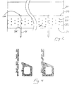
- the formwork element according to the invention is designated 31/32, it sits on the leveled Sole 111 of an excavation pit 11 and intercepts that of the formwork elements 31/32 limited formwork area entered in a flowable state Concrete 21. At 211, one is applied beforehand to the leveled underground 112 Layer of lean concrete, the so-called cleanliness layer.
- the formwork wall of the which takes over the function of the conventional formwork panel Formwork element 31/32 is designated 31.
- the inside of the formwork wall 31 extends over its length undercut grooves 312 formed, the permanent, form-fitting summary the formwork element 31/32 with the introduced, hardened concrete 21 result.
- the drainage channel taking over the function of the conventional drainage pipes 32 molded, which is offset against the formwork wall 31, from what the vertical projection 311 1 of the formwork wall 31 over the drainage channel 32 results.
- the formwork element 31/32 increasing its stability, a protrusion 321 'over the drainage channel 32.
- Over the length of the drainage channel 32 are in the outer wall 322 at a distance one above the other rows of drainage holes 324 ..., 324 ', if necessary then also formed side by side over head (323) (FIG. 2).
- Over head (323) and bottom (321) are in the drainage channel 32 at a distance from each other aligned passages 326, 326 'for placing drivable in the underground 112
- Ground nails 41 to fix the position of the formwork elements 31/32 until hardening of the concrete 21 introduced into the formwork area. After curing of the concrete, the pegs 41 can be pulled again.
- the outer walls 22 of the structure to be constructed are concreted onto the floor slab 21, the projection 311 'of the formwork wall 31 over the base plate 21 for then also desired sealing of the butt joint 23 between the base plate 21 and the outer wall 22 contributes.
- the component of the formwork element 31/32 forming drainage channel 32 can then on the outer wall after curing 22 under limited, namely with the recess of the vertical, with drainage holes 324 ..., 324 '...
- the drainage channel 32 then also forms one Easy-to-assemble base for possibly also on the outer wall 22 Insulation panels to be attached 62.
- the construction pit 11 is completed after the shell construction backfilled, if necessary with excavation from the construction pit, in the area close to the building with filter gravel.
- water passes through drainage holes 324, 324 '... in the drainage channel 32 (arrow sequence A, A' in Figure 1) through which the water is discharged (arrow A "in Figure 2).
- a trough-shaped design of the sole 321 'of the drainage channel 32 contributes to the fact that it is otherwise in the bottom area Deposited solids from the surface water entering the drainage channel get carried away.
- the formwork wall and the drainage channel can be set first also create independently and if necessary summarize form-fitting, as indicated in Figure 4. This also opens up the possibility of Formwork wall independently, i.e. without using the drainage channel.
Landscapes
- Engineering & Computer Science (AREA)
- Mining & Mineral Resources (AREA)
- Life Sciences & Earth Sciences (AREA)
- General Life Sciences & Earth Sciences (AREA)
- Paleontology (AREA)
- Civil Engineering (AREA)
- General Engineering & Computer Science (AREA)
- Structural Engineering (AREA)
- Underground Structures, Protecting, Testing And Restoring Foundations (AREA)
- Forms Removed On Construction Sites Or Auxiliary Members Thereof (AREA)
Abstract
Description
der dem zu betonierenden Bereich zugewandten Schalungswand und einem mit der Schalungswand zusammengefassten, sich auf der von der Innenseite abgewandten Seite der Schalungswand über die Länge des Schalungselementes erstreckenden, gegenüber der Schalungswand abgesetzten, geschlossenen Entwässerungskanal
in dessen Außenwandung im Abstand voneinander nebeneinander Entwässerungslöcher ausgebildet sind,
gekennzeichnet ist. Ausgestaltungen der erfindungsgemäßen bleibenden Schalung ergeben sich aus den Unteransprüchen 2 bis 11.
Es zeigen
- Figur 1
- einen Vertikalschnitt durch ein angesetztes Schalungselement, der Beton bereits eingebracht, abgebrochen,
- Figur 2
- eine Ansicht der Figur 1 in Richtung des Pfeiles II in Figur 1
- Figur 3
- eine im wesentlichen der Figur 1 entsprechende Ausbausituation, abgebrochen.
- Figur 4
- einen Vertikalschnitt durch eine Variante des Schalungselementes im Vertikalschnitt
Claims (11)
- Bleibende Schalung für eine auf planiertem Boden aufsitzende Betonplatte, gekennzeichnet durch stoßend zu verlegende, den zu betonierenden Bereich eingrenzende, gestreckte Schalungselemente aus dauerfestem Material, bestehend aus
der dem zu betonierenden Bereich zugewandten Schalungswand (31) und einem mit der Schalungswand (31) zusammengefassten, sich auf der von der Innenseite abgewandten Seite der Schalungswand (31) über die Länge des Schalungselementes (31/32) erstreckenden, gegenüber der Schalungswand (31) abgesetzten, geschlossenen Entwässerungskanal (32) in dessen Außenwandung (322) im Abstand voneinander nebeneinander Entwässerungslöcher (324...) ausgebildet sind. - Bleibende Schalung nach Anspruch 1, gekennzeichnet durch einen stetigen Übergang vom Entwässerungskanal (32) in den Überstand (311) der Schalungswand (31) über den Entwässerungskanal (32).
- Bleibende Schalung nach Anspruch 1 oder Anspruch 2, gekennzeichnet durch im Abstand voneinander übereinander bzw. nebeneinander ausgebildete Reihen von Entwässerungslöchern (324..., 324'...).
- Bleibende Schalung nach einem der Ansprüche 1 bis 3, gekennzeichnet durch eine wannenförmig ausgebildete Sohle (321" in Figur 3) des Entwässerungskanals (32).
- Bleibende Schalung nach einem der Ansprüche 1 bis 4, gekennzeichnet durch einen Überstand (321') des Bodens (321) über den Entwässerungskanal (32).
- Bleibende Schalung nach einem der Ansprüche 1 bis 5, gekennzeichnet durch fluchtende Löcher (326, 326') in der Abdeckung (323) und im Boden (321) des Entwässerungskanals (32) für das Setzen von Erdnägeln (41).
- Bleibende Schalung nach einem der Ansprüche 1 bis 6, dadurch gekennzeichnet, dass an der Innenseite der Schalungswand (31) in an sich bekannter Weise sich über die Länge der Schalungswand (31) erstreckende Nuten (312) ausgebildet sind.
- Bleibende Schalung nach Anspruch 7, gekennzeichnet durch hinterschnittene Nuten (312).
- Bleibende Schalung nach einem der Ansprüche 1 bis 8, gekennzeichnet durch die stirnseitige Ausbildung des Schalungselementes im Bereich des Entwässerungskanals (32) für eine Muffenverbindung.
- Bleibende Schalung nach einem der Ansprüche 1 bis 9, gekennzeichnet durch deren einstückige Ausbildung.
- Bleibende Schalung nach einem der Ansprüche 1 bis 9, dadurch gekennzeichnet, dass der Entwässerungskanal (32) mit der Schalungswand (31) durch Formschluss zusammengefasst ist.
Applications Claiming Priority (2)
| Application Number | Priority Date | Filing Date | Title |
|---|---|---|---|
| DE2001119975 DE10119975A1 (de) | 2001-04-24 | 2001-04-24 | Bleibende Schalung für eine auf festem planierten Boden aufsitzende Betonplatte mit integrierter Drainage |
| DE10119975 | 2001-04-24 |
Publications (2)
| Publication Number | Publication Date |
|---|---|
| EP1253251A2 true EP1253251A2 (de) | 2002-10-30 |
| EP1253251A3 EP1253251A3 (de) | 2002-12-18 |
Family
ID=7682481
Family Applications (1)
| Application Number | Title | Priority Date | Filing Date |
|---|---|---|---|
| EP02009010A Withdrawn EP1253251A3 (de) | 2001-04-24 | 2002-04-23 | Bleibende Schalung mit Drainage für eine Betonplatte |
Country Status (2)
| Country | Link |
|---|---|
| EP (1) | EP1253251A3 (de) |
| DE (1) | DE10119975A1 (de) |
Cited By (2)
| Publication number | Priority date | Publication date | Assignee | Title |
|---|---|---|---|---|
| DE102004058795A1 (de) * | 2004-12-07 | 2006-06-08 | Ilya Fershtandiker | Verlorene Schalung für eine Fundamentsohle und Verfahren zu deren Anwendung |
| DE102006044915A1 (de) * | 2006-09-22 | 2008-04-03 | Viebrockhaus Ag | Gründung eines Gebäudes |
Citations (2)
| Publication number | Priority date | Publication date | Assignee | Title |
|---|---|---|---|---|
| DE19648365C1 (de) | 1996-09-16 | 1998-05-14 | Wacon Gmbh Walter Consulting & | Seitenabschalung für Fundamente |
| DE19722951C1 (de) | 1997-05-31 | 1999-06-17 | Thomas Dipl Ing Salzer | Schalungs- und Dränelement zur Herstellung von im Erdreich angeordneten Bauwerksteilen aus Ortbeton |
Family Cites Families (3)
| Publication number | Priority date | Publication date | Assignee | Title |
|---|---|---|---|---|
| JPH07216906A (ja) * | 1994-01-31 | 1995-08-15 | Akira Tanaka | 建築用基礎及び建築方法 |
| FR2732384B1 (fr) * | 1995-03-31 | 1997-11-21 | Toffolo Albert | Panneau de coffrage drainant et etanche pour mur en beton, tel qu'un mur de soutenement |
| CA2194433C (en) * | 1996-01-04 | 2008-04-22 | Joseph Bevilacqua | Drainage pipe |
-
2001
- 2001-04-24 DE DE2001119975 patent/DE10119975A1/de not_active Ceased
-
2002
- 2002-04-23 EP EP02009010A patent/EP1253251A3/de not_active Withdrawn
Patent Citations (2)
| Publication number | Priority date | Publication date | Assignee | Title |
|---|---|---|---|---|
| DE19648365C1 (de) | 1996-09-16 | 1998-05-14 | Wacon Gmbh Walter Consulting & | Seitenabschalung für Fundamente |
| DE19722951C1 (de) | 1997-05-31 | 1999-06-17 | Thomas Dipl Ing Salzer | Schalungs- und Dränelement zur Herstellung von im Erdreich angeordneten Bauwerksteilen aus Ortbeton |
Cited By (4)
| Publication number | Priority date | Publication date | Assignee | Title |
|---|---|---|---|---|
| DE102004058795A1 (de) * | 2004-12-07 | 2006-06-08 | Ilya Fershtandiker | Verlorene Schalung für eine Fundamentsohle und Verfahren zu deren Anwendung |
| DE102004058795B4 (de) * | 2004-12-07 | 2007-01-04 | Ilya Fershtandiker | Verlorene Schalung für eine Fundamentsohle und Verfahren zu deren Anwendung |
| DE102006044915A1 (de) * | 2006-09-22 | 2008-04-03 | Viebrockhaus Ag | Gründung eines Gebäudes |
| DE102006044915B4 (de) * | 2006-09-22 | 2016-02-18 | Viebrockhaus Ag | Verfahren zur Erstellung einer Gründung eines Gebäudes |
Also Published As
| Publication number | Publication date |
|---|---|
| DE10119975A1 (de) | 2002-11-21 |
| EP1253251A3 (de) | 2002-12-18 |
Similar Documents
| Publication | Publication Date | Title |
|---|---|---|
| DE69936511T2 (de) | Verfahren zum verbinden und herstellen von lastübertragungsfähigkeit zwischen betonteilen | |
| DE69611931T2 (de) | Unterirdisches bauwerk, insbesondere für die herstellung von tunnels, unterführungen, tiefgaragen, etc. und sein herstellungsverfahren | |
| KR102131653B1 (ko) | 친환경 옹벽패널과 이용한 옹벽구조 및 구축방법 | |
| DE20307802U1 (de) | Kunststoffrinne | |
| JP3829319B2 (ja) | 地下中空構造物の施工方法とその地下中空構造物 | |
| DE60317779T2 (de) | Bogensysteme | |
| AT391731B (de) | Deckenplatte und verfahren zu ihrer herstellung sowie anordnung zur durchfuehrung des verfahrens | |
| DE60002318T2 (de) | Verfahren zur bildung eines wasserdichtes und die kriechgrenze steigernden abschnittes | |
| EP1253251A2 (de) | Bleibende Schalung mit Drainage für eine Betonplatte | |
| US5871307A (en) | Pre-cast concrete panel wall | |
| EP2198095B1 (de) | Verfahren zur herstellung eines bauwerkteils mit einem schalungselement und danach hergestelltes bauwerkteil | |
| DE2623179C2 (de) | Verfahren zur Herstellung unterirdischer Hohlräume | |
| DE20122274U1 (de) | Bleibende Schalung für eine auf planiertem Boden aufsitzende Betonplatte | |
| KR20010028793A (ko) | 마이크로 파일을 이용한 프리캐스트 옹벽 | |
| DE3902065C2 (de) | ||
| DE29602796U1 (de) | Bauelement für Frostschürze und für Mauerkrone | |
| EP1457609B1 (de) | Gebäudegeschoss | |
| DE2658890C2 (de) | Becken zum Absetzen von in Wasser befindlichen Schwebstoffen, als Filterbecken, Schlammbecken, Klärbecken o.dgl | |
| DE6609772U (de) | Bauteil zur herstellung von schlitz- oder bohrpfahlwaenden. | |
| DE3915483A1 (de) | Anordnung an einer stossfuge von beton-bodenplatten | |
| DE4302986C2 (de) | Verfahren zur Herstellung eines Bauwerks in Deckelbauweise mit Stahlbetonfertigteil-Pfählen | |
| JP3644652B2 (ja) | 連壁工法 | |
| DE19814493C2 (de) | Verfahren zur Herstellung von Außenwänden von in wasserführendes Erdreich eingelassenen Räumen | |
| EP1553230B1 (de) | Verfahren zum Abfangen von Stützmauern | |
| DE1659099C (de) | Betonformstein zur Herstellung einer Dranschicht an einer im Erdboden einge betteten Gebäudewand |
Legal Events
| Date | Code | Title | Description |
|---|---|---|---|
| PUAI | Public reference made under article 153(3) epc to a published international application that has entered the european phase |
Free format text: ORIGINAL CODE: 0009012 |
|
| AK | Designated contracting states |
Kind code of ref document: A2 Designated state(s): AT BE CH CY DE DK ES FI FR GB GR IE IT LI LU MC NL PT SE TR |
|
| AX | Request for extension of the european patent |
Free format text: AL;LT;LV;MK;RO;SI |
|
| PUAL | Search report despatched |
Free format text: ORIGINAL CODE: 0009013 |
|
| AK | Designated contracting states |
Kind code of ref document: A3 Designated state(s): AT BE CH CY DE DK ES FI FR GB GR IE IT LI LU MC NL PT SE TR |
|
| AX | Request for extension of the european patent |
Free format text: AL;LT;LV;MK;RO;SI |
|
| 17P | Request for examination filed |
Effective date: 20030613 |
|
| AKX | Designation fees paid |
Designated state(s): AT BE CH CY DE DK ES FI FR GB GR IE IT LI LU MC NL PT SE TR |
|
| GRAP | Despatch of communication of intention to grant a patent |
Free format text: ORIGINAL CODE: EPIDOSNIGR1 |
|
| STAA | Information on the status of an ep patent application or granted ep patent |
Free format text: STATUS: THE APPLICATION HAS BEEN WITHDRAWN |
|
| 18W | Application withdrawn |
Effective date: 20080306 |