EP1253280B1 - Sicherheitsverankerungsvorrichtung - Google Patents
Sicherheitsverankerungsvorrichtung Download PDFInfo
- Publication number
- EP1253280B1 EP1253280B1 EP02076587A EP02076587A EP1253280B1 EP 1253280 B1 EP1253280 B1 EP 1253280B1 EP 02076587 A EP02076587 A EP 02076587A EP 02076587 A EP02076587 A EP 02076587A EP 1253280 B1 EP1253280 B1 EP 1253280B1
- Authority
- EP
- European Patent Office
- Prior art keywords
- rail
- carriage
- assembly according
- cam
- ladder
- Prior art date
- Legal status (The legal status is an assumption and is not a legal conclusion. Google has not performed a legal analysis and makes no representation as to the accuracy of the status listed.)
- Expired - Lifetime
Links
- 229910052782 aluminium Inorganic materials 0.000 claims description 17
- XAGFODPZIPBFFR-UHFFFAOYSA-N aluminium Chemical compound [Al] XAGFODPZIPBFFR-UHFFFAOYSA-N 0.000 claims description 17
- 210000000078 claw Anatomy 0.000 claims description 10
- 229910052751 metal Inorganic materials 0.000 claims description 6
- 239000002184 metal Substances 0.000 claims description 6
- 230000000694 effects Effects 0.000 claims description 4
- 238000004873 anchoring Methods 0.000 claims description 3
- 229910001220 stainless steel Inorganic materials 0.000 claims description 2
- 239000010935 stainless steel Substances 0.000 claims description 2
- 238000002788 crimping Methods 0.000 claims 1
- 229910000831 Steel Inorganic materials 0.000 description 5
- 239000010959 steel Substances 0.000 description 5
- 229910000746 Structural steel Inorganic materials 0.000 description 3
- 239000000463 material Substances 0.000 description 3
- 238000010521 absorption reaction Methods 0.000 description 2
- 230000000295 complement effect Effects 0.000 description 2
- 238000009434 installation Methods 0.000 description 2
- 230000035515 penetration Effects 0.000 description 2
- 230000001105 regulatory effect Effects 0.000 description 2
- 208000004067 Flatfoot Diseases 0.000 description 1
- 208000027418 Wounds and injury Diseases 0.000 description 1
- 239000004411 aluminium Substances 0.000 description 1
- 230000005540 biological transmission Effects 0.000 description 1
- 230000000903 blocking effect Effects 0.000 description 1
- 230000009194 climbing Effects 0.000 description 1
- 230000007797 corrosion Effects 0.000 description 1
- 238000005260 corrosion Methods 0.000 description 1
- 230000006378 damage Effects 0.000 description 1
- 230000001419 dependent effect Effects 0.000 description 1
- 208000014674 injury Diseases 0.000 description 1
- 238000004519 manufacturing process Methods 0.000 description 1
- 238000005259 measurement Methods 0.000 description 1
- 239000002990 reinforced plastic Substances 0.000 description 1
- 230000002441 reversible effect Effects 0.000 description 1
- 230000002747 voluntary effect Effects 0.000 description 1
- 238000003466 welding Methods 0.000 description 1
Images




Classifications
-
- E—FIXED CONSTRUCTIONS
- E06—DOORS, WINDOWS, SHUTTERS, OR ROLLER BLINDS IN GENERAL; LADDERS
- E06C—LADDERS
- E06C7/00—Component parts, supporting parts, or accessories
- E06C7/18—Devices for preventing persons from falling
- E06C7/186—Rail or rope for guiding a safety attachment, e.g. a fall arrest system
- E06C7/187—Guiding rail
-
- B—PERFORMING OPERATIONS; TRANSPORTING
- B66—HOISTING; LIFTING; HAULING
- B66B—ELEVATORS; ESCALATORS OR MOVING WALKWAYS
- B66B5/00—Applications of checking, fault-correcting, or safety devices in elevators
Definitions
- the present invention relates to a mounting carriage to be installed on a profiled element acting as a rail, more particularly a vertical rail for example secured to a ladder.
- the device should be able to be installed on existing ladders and allow the per person to use it to go up and down safely.
- This equipment should also be suitable for use by several people simultaneously on the same installation.
- a fall arrest anchor carriage sliding along a rigid vertical rail so as to be able to follow the location of a user moving vertically, for example along a ladder, which is attach to it for example with a carabiner.
- the invention proposes in particular to remedy this drawback. More specifically, the invention relates to a device consisting of a trolley with wheels and a rail along which said carriage can move, the rail being placed on a vertical support, said carriage being provided with a braking cam mounted on an axis with a spring, and having at the outer end of said cam an anchor point and at the opposite end a claw adapted to pivot and rub against a flat of said rail and thus block the carriage, when a force to the bottom is abruptly applied to the anchor point.
- the device is characterized in that the carriage is made of hard metal and the metal rail is softer and in that said claw is leveraged to penetrate substantially into the softer metal during said locking with braking.
- a device comprising a trolley with wheels sliding vertically on a rail and provided with a brake cam with an axis and a spring.
- the carriage is made of steel, for example stainless steel and is preferably cut in the mass.
- the parts are preferably chemically treated to ensure good sliding between the moving parts and to avoid any corrosion.
- the brake cam is provided with a notch at one end for introducing a fastening or anchoring means such as a carabiner which links it directly or indirectly to the user, and a braking claw at the other end. .
- the rigid belay support is an extruded aluminum safety rail that is placed on a vertical support, the carriage is placed on the flat T-shaped aluminum safety rail so that it can not be detach only by one end.
- the user equipped with a harness connects for example with a carabiner attached to his harness (with sternal anti-fall arrest loop) at the end of the brake cam of the carriage provided with said anchor point.
- the steel brake cam locks on the aluminum rail by a lever effect.
- the claw of the steel brake cam crushes and penetrates the softer aluminum (eg F22 grade).
- a stop is provided to prevent the cam from tipping over the penetration thickness of the cam in the aluminum.
- This principle of crushing aluminum allows a smooth braking and a significant absorption of the fall forces and thus limits the bodily injury of a user.
- step stops with a pivotable flap.
- These stops are made of anodized aluminum, with a self-closing valve preventing untimely exit of the truck (a voluntary operation is necessary) and two polarizers placed asymmetrically to avoid placing the truck upside down.
- the rail used with the trolley of the invention is preferably a profile provided with a plate on which the carriage runs. It will be for example aluminum AlMgSi0.5 extruded.
- a slide is integrated in the rail to accommodate bolt heads component fixing which supports the rail. The fixings are separated from 1 to 2 meters maximum.
- each joint rail ends is provided with 2 junction plates (fishplates) provided with 4 holes each and 4 bolts.
- One dish is placed in the slide (tapped hole) and another on the outside (unthreaded holes).
- These bolts in the holes allow a connection of the rails to each other, ensuring proper alignment, and withstanding a pulling width of up to 1,500 kg as required by standards regulating this kind of equipment.
- the ladders may also be of the angle type, such as those used to access the top of lattice-type power transmission towers. It is then an angle provided with bolts of a length of +/- 15 cm which are fixed on the wings of this angle and serve as steps.
- this is an aluminum T-rail and a fall-prevention trolley that slides on this aluminum T-rail.
- a Y-fastening device is proposed in order to fix said rail on an angle. If this fixing was to be made of steel, it should be welded in 4 places and in line, which leads to a significant manufacturing time and less reliability due to welding.
- the invention therefore proposes a profiled element in Y, Y whose vertical branch comprises a horizontal foot.
- the element is made of aluminum and can be extruded, cut and drilled, the opening of the arms of the Y adapting to the angle forming the ladder, and the flat foot extending from a distance of one side beyond Y, distance or section where a perforation is provided for the passage of a screw or nut to be fixed to the aforementioned safety rail.
- the vertical branch plate of the Y also has a hole to accommodate a stud. When tightening the nuts of the thrust bearings, the flange completely blocks 1 aluminum fastener on the angle.
- the offset of the flat where the bolt supporting the T-rail is fixed is calculated so that the movement of the operators on these ladders is the best and also so that there is sufficient space for the clamping nuts and the fingers installers.
- the Fig. 1 is a representation of the carriage 1 according to the invention seen from side (A) and seen in section from above (B).
- a carriage body 2 comprising hollow rollers 3 moving on a flat 14 of a vertical rail 10.
- a cam 9 can tilt about an axis 5 of the body 2 and comprises at one end an attachment point 4 and at the other end a claw 7 in contact, by action of a spring 6, with the material of the plate 14 of the rail. It is understood that a sudden downward force (arrow) of the attachment point 4 causes a tilting of the claw that penetrates into the material of the plate causing braking and the desired anti-fall effect.
- a stop 8 prevents tilting of the claw of the cam 9 beyond the thickness of material.
- the Fig. 2 is a view of a rail for the carriage 1, attached to the post 22 of a ladder in two ways. Is provided either a fastener 20 enclosing the upright 22 or a fastener 21 attached with the end of a step 23.
- the rail is held by bolts inserted into a slide 11 provided in the rail, opposite the flat slide 14 of the carriage 10.
- the Fig. 3 represents a rail 10 fixed in the middle of the ladders 23 of a ladder by fastening elements 29, and illustrates a junction of two rails (10a and 10b).
- Detail C shows the two fishplates 12 and 12 'on either side of the slide 11 clamped by bolts 13.
- Fig. 4 shows in greater detail, in elevation and in plan, a particular mode of joining two rails 10a 10b in which bolts 30 are inserted into holes 16 of the inner wall of the slide 17, also enclosing ribs 12 and 12 ' .
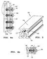
- the Fig. 5 illustrates in perspective a safety rail 10 for a carriage 1 according to the invention. We distinguish the holes 16 in the inner wall 17 of the slide 11.
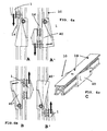
- Fig. 6 illustrates the operation of the stops (40 'and 40) made of aluminum, respectively at the lower ends (B) and upper (A) of the rails allowing the passage of the carriage 1 in one direction only, without the express manipulation of the user.
- Detail C illustrates an upper rail section with a stop 40 and polarizers 19 not allowing to slide the carriage in the right orientation, a complementary groove being provided in the carriage.
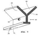
- the Fig. 7 represents a profile 50 Y fixing of the rail on an angle ladder.
- the foot of the Y has a flat which extends at 51 beyond the vertical leg and comprises in this part a hole 52.
- the intersection of the arms or wings (54, 55) of the Y intended to grip an angle iron has a rounded forming a receiving channel of the edge of the angle.
- the Fig. 8a represents a cross section and the Fig. 8b partially in elevation the attachment of a rail 10 to the profile 50 of the Fig. 7 and at the angle 60.
- the attachment of the part 50 to the rail 10 is illustrated in elevation.
- the hole 52 of the section 51 of the piece receiving a bolt 58 whose head is located in the slide 11 of the rail 10.
- the fig 9 schematically shows in perspective an angled ladder section 60 comprising two perpendicular rungs 61 and a rail attachment system 50 (not shown).
- the fixing profile 50 of the rail covering the edge of the angle iron is recognized with the elements equivalent to those described in FIGS. Figs. 8a and 8b , in particular the flange 65 and the hole 52 for attachment to the safety rail.
Landscapes
- Engineering & Computer Science (AREA)
- Mechanical Engineering (AREA)
- Ladders (AREA)
Claims (10)
- Vorrichtung mit einem Rollenschlitten (1) und einer Schiene (10), entlang der der Rollenschlitten (1) verschiebbar ist, wobei die Schiene auf einem senkrechten Träger angeordnet ist, wobei der besagte Rollenschlitten (1) mit einem Bremsnocken, der auf einer Achse (5) mit einer Feder (6) montiert ist, versehen ist und an dem äußeren Ende des besagten Nockens einen Verankerungspunkt (4) und an dem entgegen gesetzten Ende eine schwenkbare Kralle (7) aufweist, die so ausgebildet ist, dass sie an einem Flachprofil (14) der besagten schiene (10) schleift und somit den Rollenschlitten (1) blockiert, wenn plötzlich eine Kraft nach unten auf dem Verankerungspunkt (4) ausgeübt wird,
dadurch gekennzeichnet, dass
der Rollenschlitten (1) aus einem harten Metall und die schiene (10) aus einem weicheren Metall bestehen, und dass die besagte Kralle (7) dazu geeignet ist, beim Blockieren durch Bremsen in das weichere Metall unter Hebelwirkung substanziell einzudringen. - Vorrichtung nach Anspruch 1, bei dem mindestens der Nocken (8) aus rostfreiem Stahl hergestellt ist.
- Vorrichtung nach irgendeinem der vorangehenden Ansprüche, dadurch gekennzeichnet, dass die schiene (10) aus Aluminium, vorzugsweise aus einem anodisierten Aluminium besteht.
- Vorrichtung nach irgendeinem der vorangehenden Ansprüche, dadurch gekennzeichnet, dass der Rollenschlitten (1) aus einem Körper (2), einem Bremsnocken (9) mit einer Achse (5) und einer Feder (6) und aus vier Führungsrollen (3) mit vier durch Umfalzen an dem Körper (2) fixierten Achsen besteht, und dass er nicht geöffnet werden kann.
- Vorrichtung nach irgendeinem der vorangehenden Ansprüche, bei dem die Schiene (10) senkrecht verläuft.
- Vorrichtung nach irgendeinem der vorangehenden Ansprüche, dadurch gekennzeichnet, dass die Schiene (10) auf einer Leiter angeordnet ist.
- Vorrichtung nach irgendeinem der vorangehenden Ansprüche, dadurch gekennzeichnet, dass die Schiene auf einem der Träger (22) einer Leiter mit Hilfe von Befestigungselementen (20, 21) fixiert ist.
- Vorrichtung nach irgendeinem der vorangehenden Ansprüche, dadurch gekennzeichnet, dass die Schiene auf den Sprossen (23) einer Leiter mit Hilfe von Befestigungselementen (29) fixiert ist.
- Vorrichtung nach irgendeinem der vorangehenden Ansprüche, dadurch gekennzeichnet, dass der Rollenschlitten mit einer Nut für den Durchgang einer mindestens an einem Ende der Schiene (10) beim Anschlag vorgesehenen Unverwechselbarkeitsvorrichtung (19), versehen ist.
- Vorrichtung nach irgendeinem der vorangehenden Ansprüche, bei dem mehrere Rollenschlitten (1) für eine einzige Schiene vorhanden sind.
Applications Claiming Priority (2)
| Application Number | Priority Date | Filing Date | Title |
|---|---|---|---|
| BE200100273 | 2001-04-20 | ||
| BE200100273 | 2001-04-22 |
Publications (3)
| Publication Number | Publication Date |
|---|---|
| EP1253280A2 EP1253280A2 (de) | 2002-10-30 |
| EP1253280A3 EP1253280A3 (de) | 2008-12-03 |
| EP1253280B1 true EP1253280B1 (de) | 2013-02-20 |
Family
ID=3896950
Family Applications (1)
| Application Number | Title | Priority Date | Filing Date |
|---|---|---|---|
| EP02076587A Expired - Lifetime EP1253280B1 (de) | 2001-04-20 | 2002-04-22 | Sicherheitsverankerungsvorrichtung |
Country Status (2)
| Country | Link |
|---|---|
| EP (1) | EP1253280B1 (de) |
| BE (1) | BE1014789A7 (de) |
Families Citing this family (7)
| Publication number | Priority date | Publication date | Assignee | Title |
|---|---|---|---|---|
| DE10319175A1 (de) * | 2003-04-29 | 2005-01-27 | Strohm, Regina, geb. Wetzel | Sicherungsvorrichtung zur Verwendung an turmartigen Bauwerken |
| DE10319174A1 (de) * | 2003-04-29 | 2005-02-24 | Strohm, Regina, geb. Wetzel | Auffangvorrichtung zur Verwendung an turmartigen Bauwerken |
| DE102005049288A1 (de) * | 2005-10-14 | 2007-04-19 | Zarges Aluminium Systeme Gmbh | Turmleiter |
| EP1990072A1 (de) * | 2007-05-08 | 2008-11-12 | Fallprotec S.A. | Beweglicher Feststellschlitten für Sicherheitsleine |
| CA3035263C (en) | 2017-07-24 | 2019-07-30 | Sayfa R&D Pty Ltd | A modular ladder system |
| US11052270B2 (en) * | 2017-07-24 | 2021-07-06 | Sayfa R&D Pty Ltd | Vertical fall arrest safety device |
| CN116411789B (zh) * | 2023-04-13 | 2025-08-08 | 中铁一局集团有限公司 | 一种安全防护笼梯 |
Family Cites Families (4)
| Publication number | Priority date | Publication date | Assignee | Title |
|---|---|---|---|---|
| US3348632A (en) | 1965-02-16 | 1967-10-24 | William E Swager | Climbing device |
| US4085818A (en) | 1976-05-20 | 1978-04-25 | Swager William E | Plastic ladder and safety device |
| DE3425947A1 (de) * | 1984-07-13 | 1986-01-16 | Söll KG Industrieschmiede, 8670 Hof | Schlitten fuer eine steigschutzvorrichtung zum besteigen einer leiter |
| DE8606241U1 (de) * | 1986-03-07 | 1986-04-24 | Lorenz Hasenbach GmbH & Co KG, 6277 Bad Camberg | Fallschutzvorrichtung |
-
2002
- 2002-04-22 BE BE2002/0272A patent/BE1014789A7/fr not_active IP Right Cessation
- 2002-04-22 EP EP02076587A patent/EP1253280B1/de not_active Expired - Lifetime
Also Published As
| Publication number | Publication date |
|---|---|
| BE1014789A7 (fr) | 2004-04-06 |
| EP1253280A3 (de) | 2008-12-03 |
| EP1253280A2 (de) | 2002-10-30 |
Similar Documents
| Publication | Publication Date | Title |
|---|---|---|
| EP0608164B1 (de) | Bewegliche Verankerung die eine sichere waagerechte Verschiebung ermöglicht | |
| CA2397878C (fr) | Dispositif anti-chute | |
| EP1253280B1 (de) | Sicherheitsverankerungsvorrichtung | |
| EP2666518B1 (de) | Blockiervorrichtung für Laufleine mit beweglichem Drehkörper | |
| FR2589182A1 (fr) | Garde-corps de chantier | |
| EP3481509B1 (de) | Vorrichtung für sicheren zugang zu einem geschlossenen raum, insbesondere einem mit seitenzugang begrenzten raum | |
| FR2617050A1 (fr) | Dispositif de securite anti-chute coulissant sur un support d'assurance vertical ou horizontal | |
| FR2600898A1 (fr) | Organe d'assurage a taquet coinceur autobloquant pour corde fixe | |
| EP2316535A1 (de) | Kabelspannvorrichtung, die mit einer Absorbervorrichtung für Impulsbelastung ausgestattet ist | |
| EP0363234A1 (de) | Schutzvorrichtung für persönliche Absturzsicherungsausrüstung | |
| EP0407680B1 (de) | Verfahren zum Verbinden einer vorgefertigten Gerüstbühne mit einer horizontalen Traverse, und vorgefertigte Gerüstbühne dazu | |
| FR2589211A1 (fr) | Organe d'assurage a taquet coinceur pour la remontee sur une corde fixe | |
| EP2762201A1 (de) | Mobile Verankerungsvorrichtung für Schiene | |
| FR2525906A1 (fr) | Serre-cable de securite pour proteger les personnes contre les risques de chute | |
| BE1022448B1 (fr) | Dispositif de protection pour toiture a joints debout | |
| FR2899253A1 (fr) | Dispositif de securite pour l'acces a une chambre technique situee sous une chaussee ou analogue | |
| FR2480338A1 (fr) | Structure de protection pour couvreur et montant correspondant | |
| FR3029228A1 (fr) | Dispositif de liaison d'un montant notamment d'une barriere de securite pour un mur a coffrage integre | |
| EP1243705A1 (de) | Sicherheitsabdeckung zum Verschliessen von Zugangsöffnungen bei Kläranlagen | |
| BE1014716A6 (fr) | Bride pour ancrage de securite | |
| FR3072317B1 (fr) | Outil de decoupe de plaques d’ardoises a collecteur de dechets | |
| FR3163393A1 (fr) | Kit formant barre de couverture de piscine | |
| EP2317175B1 (de) | Vorrichtung zur Formung einer Kabelschleife und Absorber-Spannvorrichtung für eine Rettungsleine, die eine solche Vorrichtung umfasst | |
| FR2977266A1 (fr) | Dispositif d'ancrage temporaire d'un equipement de protection d'un intervenant en hauteur, installation de securite integrant un tel dispositif et son procede de montage | |
| FR2779064A1 (fr) | Dispositif de securite pour la fixation en elevation d'un filet pare-chute et son procede d'accrochage |
Legal Events
| Date | Code | Title | Description |
|---|---|---|---|
| PUAI | Public reference made under article 153(3) epc to a published international application that has entered the european phase |
Free format text: ORIGINAL CODE: 0009012 |
|
| AK | Designated contracting states |
Kind code of ref document: A2 Designated state(s): AT BE CH CY DE DK ES FI FR GB GR IE IT LI LU MC NL PT SE TR |
|
| AX | Request for extension of the european patent |
Free format text: AL;LT;LV;MK;RO;SI |
|
| RIC1 | Information provided on ipc code assigned before grant |
Ipc: B66B 5/00 20060101ALI20080714BHEP Ipc: E06C 7/18 20060101AFI20020715BHEP |
|
| PUAL | Search report despatched |
Free format text: ORIGINAL CODE: 0009013 |
|
| AK | Designated contracting states |
Kind code of ref document: A3 Designated state(s): AT BE CH CY DE DK ES FI FR GB GR IE IT LI LU MC NL PT SE TR |
|
| AX | Request for extension of the european patent |
Extension state: AL LT LV MK RO SI |
|
| 17P | Request for examination filed |
Effective date: 20090525 |
|
| AKX | Designation fees paid |
Designated state(s): AT BE CH CY DE DK ES FI FR GB GR IE IT LI LU MC NL PT SE TR |
|
| 17Q | First examination report despatched |
Effective date: 20100115 |
|
| REG | Reference to a national code |
Ref country code: DE Ref legal event code: R079 Ref document number: 60244521 Country of ref document: DE Free format text: PREVIOUS MAIN CLASS: E06C0007180000 Ipc: B66B0005000000 |
|
| GRAP | Despatch of communication of intention to grant a patent |
Free format text: ORIGINAL CODE: EPIDOSNIGR1 |
|
| RIC1 | Information provided on ipc code assigned before grant |
Ipc: B66B 5/00 20060101AFI20121017BHEP |
|
| GRAS | Grant fee paid |
Free format text: ORIGINAL CODE: EPIDOSNIGR3 |
|
| GRAA | (expected) grant |
Free format text: ORIGINAL CODE: 0009210 |
|
| AK | Designated contracting states |
Kind code of ref document: B1 Designated state(s): AT BE CH CY DE DK ES FI FR GB GR IE IT LI LU MC NL PT SE TR |
|
| REG | Reference to a national code |
Ref country code: GB Ref legal event code: FG4D Free format text: NOT ENGLISH |
|
| REG | Reference to a national code |
Ref country code: CH Ref legal event code: EP |
|
| REG | Reference to a national code |
Ref country code: AT Ref legal event code: REF Ref document number: 597455 Country of ref document: AT Kind code of ref document: T Effective date: 20130315 |
|
| REG | Reference to a national code |
Ref country code: IE Ref legal event code: FG4D Free format text: LANGUAGE OF EP DOCUMENT: FRENCH |
|
| REG | Reference to a national code |
Ref country code: DE Ref legal event code: R096 Ref document number: 60244521 Country of ref document: DE Effective date: 20130418 |
|
| REG | Reference to a national code |
Ref country code: AT Ref legal event code: MK05 Ref document number: 597455 Country of ref document: AT Kind code of ref document: T Effective date: 20130220 |
|
| REG | Reference to a national code |
Ref country code: NL Ref legal event code: VDEP Effective date: 20130220 |
|
| PG25 | Lapsed in a contracting state [announced via postgrant information from national office to epo] |
Ref country code: ES Free format text: LAPSE BECAUSE OF FAILURE TO SUBMIT A TRANSLATION OF THE DESCRIPTION OR TO PAY THE FEE WITHIN THE PRESCRIBED TIME-LIMIT Effective date: 20130531 Ref country code: CY Free format text: LAPSE BECAUSE OF FAILURE TO SUBMIT A TRANSLATION OF THE DESCRIPTION OR TO PAY THE FEE WITHIN THE PRESCRIBED TIME-LIMIT Effective date: 20130220 Ref country code: SE Free format text: LAPSE BECAUSE OF FAILURE TO SUBMIT A TRANSLATION OF THE DESCRIPTION OR TO PAY THE FEE WITHIN THE PRESCRIBED TIME-LIMIT Effective date: 20130220 Ref country code: AT Free format text: LAPSE BECAUSE OF FAILURE TO SUBMIT A TRANSLATION OF THE DESCRIPTION OR TO PAY THE FEE WITHIN THE PRESCRIBED TIME-LIMIT Effective date: 20130220 |
|
| PG25 | Lapsed in a contracting state [announced via postgrant information from national office to epo] |
Ref country code: PT Free format text: LAPSE BECAUSE OF FAILURE TO SUBMIT A TRANSLATION OF THE DESCRIPTION OR TO PAY THE FEE WITHIN THE PRESCRIBED TIME-LIMIT Effective date: 20130620 Ref country code: FI Free format text: LAPSE BECAUSE OF FAILURE TO SUBMIT A TRANSLATION OF THE DESCRIPTION OR TO PAY THE FEE WITHIN THE PRESCRIBED TIME-LIMIT Effective date: 20130220 Ref country code: GR Free format text: LAPSE BECAUSE OF FAILURE TO SUBMIT A TRANSLATION OF THE DESCRIPTION OR TO PAY THE FEE WITHIN THE PRESCRIBED TIME-LIMIT Effective date: 20130521 |
|
| PG25 | Lapsed in a contracting state [announced via postgrant information from national office to epo] |
Ref country code: DK Free format text: LAPSE BECAUSE OF FAILURE TO SUBMIT A TRANSLATION OF THE DESCRIPTION OR TO PAY THE FEE WITHIN THE PRESCRIBED TIME-LIMIT Effective date: 20130220 Ref country code: NL Free format text: LAPSE BECAUSE OF FAILURE TO SUBMIT A TRANSLATION OF THE DESCRIPTION OR TO PAY THE FEE WITHIN THE PRESCRIBED TIME-LIMIT Effective date: 20130220 |
|
| PG25 | Lapsed in a contracting state [announced via postgrant information from national office to epo] |
Ref country code: MC Free format text: LAPSE BECAUSE OF FAILURE TO SUBMIT A TRANSLATION OF THE DESCRIPTION OR TO PAY THE FEE WITHIN THE PRESCRIBED TIME-LIMIT Effective date: 20130220 |
|
| PLBE | No opposition filed within time limit |
Free format text: ORIGINAL CODE: 0009261 |
|
| STAA | Information on the status of an ep patent application or granted ep patent |
Free format text: STATUS: NO OPPOSITION FILED WITHIN TIME LIMIT |
|
| PG25 | Lapsed in a contracting state [announced via postgrant information from national office to epo] |
Ref country code: IT Free format text: LAPSE BECAUSE OF FAILURE TO SUBMIT A TRANSLATION OF THE DESCRIPTION OR TO PAY THE FEE WITHIN THE PRESCRIBED TIME-LIMIT Effective date: 20130220 |
|
| 26N | No opposition filed |
Effective date: 20131121 |
|
| REG | Reference to a national code |
Ref country code: IE Ref legal event code: MM4A |
|
| REG | Reference to a national code |
Ref country code: DE Ref legal event code: R097 Ref document number: 60244521 Country of ref document: DE Effective date: 20131121 |
|
| PG25 | Lapsed in a contracting state [announced via postgrant information from national office to epo] |
Ref country code: IE Free format text: LAPSE BECAUSE OF NON-PAYMENT OF DUE FEES Effective date: 20130422 |
|
| PG25 | Lapsed in a contracting state [announced via postgrant information from national office to epo] |
Ref country code: TR Free format text: LAPSE BECAUSE OF FAILURE TO SUBMIT A TRANSLATION OF THE DESCRIPTION OR TO PAY THE FEE WITHIN THE PRESCRIBED TIME-LIMIT Effective date: 20130220 |
|
| REG | Reference to a national code |
Ref country code: FR Ref legal event code: PLFP Year of fee payment: 15 |
|
| PGFP | Annual fee paid to national office [announced via postgrant information from national office to epo] |
Ref country code: GB Payment date: 20160421 Year of fee payment: 15 Ref country code: DE Payment date: 20160421 Year of fee payment: 15 |
|
| REG | Reference to a national code |
Ref country code: FR Ref legal event code: PLFP Year of fee payment: 16 |
|
| REG | Reference to a national code |
Ref country code: DE Ref legal event code: R119 Ref document number: 60244521 Country of ref document: DE |
|
| GBPC | Gb: european patent ceased through non-payment of renewal fee |
Effective date: 20170422 |
|
| PG25 | Lapsed in a contracting state [announced via postgrant information from national office to epo] |
Ref country code: DE Free format text: LAPSE BECAUSE OF NON-PAYMENT OF DUE FEES Effective date: 20171103 |
|
| PG25 | Lapsed in a contracting state [announced via postgrant information from national office to epo] |
Ref country code: GB Free format text: LAPSE BECAUSE OF NON-PAYMENT OF DUE FEES Effective date: 20170422 |
|
| REG | Reference to a national code |
Ref country code: FR Ref legal event code: PLFP Year of fee payment: 17 |
|
| PGFP | Annual fee paid to national office [announced via postgrant information from national office to epo] |
Ref country code: LU Payment date: 20210426 Year of fee payment: 20 |
|
| PGFP | Annual fee paid to national office [announced via postgrant information from national office to epo] |
Ref country code: FR Payment date: 20210427 Year of fee payment: 20 |
|
| PGFP | Annual fee paid to national office [announced via postgrant information from national office to epo] |
Ref country code: BE Payment date: 20210426 Year of fee payment: 20 Ref country code: CH Payment date: 20210428 Year of fee payment: 20 |
|
| REG | Reference to a national code |
Ref country code: BE Ref legal event code: MK Effective date: 20220422 |
|
| REG | Reference to a national code |
Ref country code: CH Ref legal event code: PL |