EP1253295A2 - Axialturbine mit einer Stufe in einem Abströmkanal - Google Patents
Axialturbine mit einer Stufe in einem Abströmkanal Download PDFInfo
- Publication number
- EP1253295A2 EP1253295A2 EP02004029A EP02004029A EP1253295A2 EP 1253295 A2 EP1253295 A2 EP 1253295A2 EP 02004029 A EP02004029 A EP 02004029A EP 02004029 A EP02004029 A EP 02004029A EP 1253295 A2 EP1253295 A2 EP 1253295A2
- Authority
- EP
- European Patent Office
- Prior art keywords
- axial
- turbine
- flow
- rotor blades
- stage rotor
- Prior art date
- Legal status (The legal status is an assumption and is not a legal conclusion. Google has not performed a legal analysis and makes no representation as to the accuracy of the status listed.)
- Granted
Links
Images


Classifications
-
- F—MECHANICAL ENGINEERING; LIGHTING; HEATING; WEAPONS; BLASTING
- F01—MACHINES OR ENGINES IN GENERAL; ENGINE PLANTS IN GENERAL; STEAM ENGINES
- F01D—NON-POSITIVE DISPLACEMENT MACHINES OR ENGINES, e.g. STEAM TURBINES
- F01D5/00—Blades; Blade-carrying members; Heating, heat-insulating, cooling or antivibration means on the blades or the members
- F01D5/12—Blades
- F01D5/14—Form or construction
- F01D5/141—Shape, i.e. outer, aerodynamic form
- F01D5/142—Shape, i.e. outer, aerodynamic form of the blades of successive rotor or stator blade-rows
- F01D5/143—Contour of the outer or inner working fluid flow path wall, i.e. shroud or hub contour
-
- F—MECHANICAL ENGINEERING; LIGHTING; HEATING; WEAPONS; BLASTING
- F01—MACHINES OR ENGINES IN GENERAL; ENGINE PLANTS IN GENERAL; STEAM ENGINES
- F01D—NON-POSITIVE DISPLACEMENT MACHINES OR ENGINES, e.g. STEAM TURBINES
- F01D25/00—Component parts, details, or accessories, not provided for in, or of interest apart from, other groups
- F01D25/30—Exhaust heads, chambers, or the like
Definitions
- the present invention relates to an axial-flow turbine and, particularly, to a gas turbine in which the pressure between a turbine and a diffuser is locally increased so that the thermal efficiency is increased.
- Japanese Unexamined Patent Publications (Kokai) No. 5-321896 and No. 11-148497 disclose a solution in which the shape of the front side or the back side of a blade is modified so that the pressure loss caused by shock waves is decreased.
- a blade for example, a rotor blade in which the shape of the front side or the backside thereof is modified, is disclosed.
- Kokai No. 11-148497 a blade, for example, a rotor blade in which the maximum thickness portion of the blade is changed from a position of 40% of a chord length to a position of 60% of the chord length, is disclosed.
- the object of the present invention is to further reduce the pressure loss, caused by shock waves in the vicinity of a tip portion trailing edge of terminal stage rotor blades, so as to improve the efficiency of the axial-flow turbine by modifying the shape of the tip portion of the blades and the shape of the axial-flow turbine passage e.g. the gas turbine passage.
- an axial-flow turbine comprising an exhaust chamber; a turbine including multiple stage rotor blades, said multiple stage rotor blades including terminal stage rotor blades; an annular diffuser located between the turbine and the exhaust chamber; and an annular axial-flow turbine passage defined by the turbine, the diffuser and the exhaust chamber, wherein fluid flows through the axial-flow turbine passage toward the exhaust chamber, and an annular stepped portion which inwardly projects in a radial direction is formed on the portion of an inner wall of the axial-flow turbine passage that is located on the downstream side of a trailing edge of a tip portion of the terminal stage rotor blades provided in the flow direction of the fluid.
- the streamline of a fluid passing through the axial-flow turbine passage is inwardly curved between the tip portion trailing edge and the upstream end portion of the stepped portion so that variations in the streamline occurs. Therefore, the pressure is increased to reduce the Mach number, and the pressure loss is decreased to improve the turbine efficiency. Additionally, the Mach number is decreased to reduce the occurrence of shock waves and, thus, damage to the tip portion of the rotor blade can be prevented.
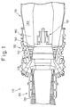
- Fig. 1 shows a longitudinal partly sectional view of an axial-flow turbine, e.g. a gas turbine in a related art.
- An axial-flow turbine e.g. a gas turbine 110 contains a compressor 130 to compress intaken air, at least one combustor 140 provided on the downstream side of the compressor 130 in the direction of the air flow, a turbine 150 provided on the downstream side of the combustor 140, a diffuser 160 provided on the downstream side of the turbine and an exhaust chamber 170 provided on the downstream side of the diffuser 160.
- the axial-flow turbine e.g. the gas turbine 110
- the compressor 130, the turbine 150, the diffuser 160 and the exhaust chamber 170 define an annular axial-flow turbine passage e.g. gas turbine passage 180.
- the compressor contains, in a compressor casing 139, compressor rotor blades and compressor stay blades composed of multiple-stages.
- the turbine 150 contains, in the turbine casing 159, rotor blades and stay blades composed of multiple-stages. As shown in the drawing, the compressor 130 and the turbine 150 are provided on a rotating shaft 190.
- the turbine 150 has the multiple-stage stay blades which is provided on the inner wall of the gas turbine passage 180 and the multiple-stage rotor blades provided on the rotating shaft 190. At each stage of the multiple-stage rotor blades, a plurality of rotor blades are spaced substantially at an equal distance, in the circumferential direction, around the rotating shaft 190.
- Fluid for example, air enters through the inlet (not shown) of the compressor 130 and passes through the compressor 130 to be compressed.
- the fluid is mixed , in the combustor 140, with the fuel to be burnt, and passes through the turbine 150 provided with multiple-stage blades, for example, four-stage blades. Then, the fluid is discharged through the exhaust chamber 170 via the diffuser 160.
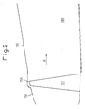
- Fig. 2 shows an enlarged view of surroundings of the turbine 150 and the diffuser 160 of the gas turbine 110.
- a rotor blade 151 of the terminal stage rotor blades of the turbine 150 is shown.
- blades other than the terminal stage rotor blades are omitted.
- the tip portion of the rotor blade 151 substantially linearly extends along the inner wall of the gas turbine passage 180.
- the inner wall of the gas turbine passage 180 in the turbine 150 is formed so that the radius of the inner wall is increased toward the downstream side in the direction of the air flow (indicated by an arrow "F").
- the inner wall of the gas turbine passage 180 in the diffuser 160 is formed so that the radius of the inner wall is increased toward the downstream side. Therefore, the fluid which passes through the turbine 150 enters into the diffuser 160 while outwardly and radially spreading from the rotating shaft 190.
- the mechanical load of the turbine itself is increased.
- the velocity of the fluid increases and the Mach number increases in the vicinity of the tip portion of the rotor blade 151.
- the Mach number is extremely increased.
- pressure loss caused by shock waves tends to increase.
- the tip portion of the rotor blades may be partially broken by the shock wave produced by increasing the Mach number as described above.
- Fig. 3 shows a longitudinal partly sectional view of a first embodiment of the axial-flow turbine, e.g. a gas turbine according to the present invention.
- the turbine 50 contains a terminal stage rotor blade 51 of terminal stage rotor blades.
- blades other than the terminal stage rotor blade are omitted in the drawing.
- the inner wall of the axial-flow turbine passage e.g. a gas turbine passage 80 in the turbine 50, is formed so that the radius of the inner wall is increased toward the downstream side in the direction of the air flow (indicated by an arrow "F").
- the inner wall of the gas turbine passage 80 in the diffuser 60 is formed so that the radius of the inner wall is increased toward the downstream side.
- annular stepped portion 20 is provided on the downstream side of the tip portion leading edge 56 of the rotor blade 51.
- the stepped portion 20 inwardly and radially projects from a part of the inner wall of the gas turbine passage 80, which is nearest to the tip portion trailing edge 56 of the rotor blade 51, to the tip portion trailing edge 56.
- An upstream end portion 21 of the stepped portion 20 and the tip portion trailing edge 56 are not in contact with each other.
- the stepped portion 20 extends from the upstream end portion 21 of the stepped portion 20 toward the downstream side and the exhaust chamber 70 (not shown) in the gas turbine passage 80 in the diffuser 60.
- the stepped portion 20 has a linear portion 22 extending substantially in parallel with the central axis of a rotating shaft (not shown). If the stepped portion 20 has the linear portion 22, the stepped portion 20 can be easily formed.
- the stepped portion 20 is slightly outwardly curved at a curved portion 23, and outwardly extends, toward the downstream side, along the inner wall of the gas turbine passage 80 in the diffuser 60.
- the distance between the central axis of the rotating shaft and the upstream end portion 21 of the stepped portion 20 is substantially identical to that between the central axis and the tip portion trailing edge 56 of the rotor blade 51.
- the stepped portion 20 causes the streamline which represents a flow direction of the fluid to vary so that the streamline is strongly curved between the stepped portion 20 and the tip portion trailing edge 56 and, especially, between the upstream side end portion 21 and the tip portion trailing edge 56. Therefore, the pressure is locally increased at a portion in which the above-described variations in streamline are produced. Consequently, the Mach number is decreased between the stepped portion 20 and the tip portion trailing edge 56 and, especially, between the upstream end portion 21 and the tip portion trailing edge 56, thus resulting in reduction of the pressure loss.
- the distance between the central axis and the upstream end portion 21 is substantially identical to that between the central axis and the tip portion trailing edge 56.
- the Mach number can be decreased to reduce the pressure loss.
- the Mach number can be decreased to reduce the pressure loss.
- Fig. 4 shows a longitudinal partly sectional view of a second embodiment of an axial-flow turbine, e.g. a gas turbine, according to the present invention.
- a linear portion 22 extending from the upstream end portion 21 substantially in parallel with the central axis, is formed.
- the stepped portion 20 has a projecting portion 24 which further projects toward the inside.
- the projecting portion 24 exists on the downstream side of the linear portion 22 of the stepped portion 20.
- the stepped portion 20 causes the streamline which represents the flow direction of the fluid to vary so that the streamline is strongly inwardly curved between the stepped portion 20 and the tip portion trailing edge 56, along the projecting portion 24. Therefore, the pressure is locally increased at a portion in which variations in streamline occurs. Consequently, the Mach number is further decreased between the stepped portion 20 and the tip portion trailing edge 56, thus resulting in a reduction in the pressure loss.
- the projecting portion 24 can be disposed to be adjacent to the upstream end portion 21 without having the linear portion 22 in the second embodiment.
- the pressure loss can be further decreased and the turbine efficiency can be further increased.
- the Mach number can be decreased to decrease the pressure loss, and the turbine efficiency can be increased.
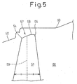
- Fig. 5 shows an enlarged view of another embodiment of surroundings of the tip portion of a terminal stage rotor blade of an axial-flow turbine, e.g. a gas turbine, according to the present invention.
- a portion between the tip portion leading edge and the tip portion trailing edge of the terminal stage rotor blade 151 substantially linearly extends.
- a curved portion 57 which is outwardly curved in a radial direction is provided between the tip portion leading edge 54 and the tip portion trailing edge 56 of the terminal stage rotor blade 51.
- the streamline of the fluid is inwardly curved in a radial direction on the downstream side of the curved portion 57. Therefore, the streamline in the vicinity of the tip portion trailing edge 56 is curved more than that of a related art. Consequently, Mach number is decreased as the pressure is increased, and the pressure loss can be decreased.
- a maximum curvature point 58 in which a curvature of the curved portion 57 reaches maximum is located on the downstream side of an axial direction center line 59 of the terminal stage rotor blade 51 in the flow direction of the fluid. Therefore, the variations in streamline in this embodiment are larger than that in case of the maximum curvature point 58 in the curved portion 57 located on the upstream side of the axial direction center line 59 or located on the axial direction center line 59. Accordingly, in this embodiment, the Mach number can be further decreased and the pressure loss can be further decreased.
- first embodiment or the second embodiment can be combined with this embodiment, so that the pressure loss can be further decreased to further increase the turbine efficiency.
- shape of turbine blades and a gas turbine passage in a diffuser can be applied to the shape of a compressor blades and a gas turbine passage in a compressor.
- Fig. 6 is a view showing the shape of an axial-flow turbine, e.g. a gas turbine, according to the present invention.
- the horizontal axis represents an axial length of a gas turbine
- the vertical axis represents a distance from the central axis of a rotating shaft.
- the thick line represents a gas turbine in a related art
- the thin line represents a gas turbine (having only a linear portion 22)based on the first embodiment
- the dotted line represents a gas turbine (having a projecting portion 24 on the downstream side of the linear portion 22) based on the second embodiment, respectively.
- Fig. 7 shows the rising rate of turbine efficiency of an axial-flow turbine, e.g. a gas turbine, for each of these embodiments.
- the gas turbine efficiency can be improved by 0.13% in the first embodiment, and by 0.20% in the second embodiment.
Landscapes
- Engineering & Computer Science (AREA)
- Mechanical Engineering (AREA)
- General Engineering & Computer Science (AREA)
- Physics & Mathematics (AREA)
- Fluid Mechanics (AREA)
- Turbine Rotor Nozzle Sealing (AREA)
Applications Claiming Priority (2)
| Application Number | Priority Date | Filing Date | Title |
|---|---|---|---|
| JP2001132962A JP3564420B2 (ja) | 2001-04-27 | 2001-04-27 | ガスタービン |
| JP2001132962 | 2001-04-27 |
Publications (3)
| Publication Number | Publication Date |
|---|---|
| EP1253295A2 true EP1253295A2 (de) | 2002-10-30 |
| EP1253295A3 EP1253295A3 (de) | 2004-01-14 |
| EP1253295B1 EP1253295B1 (de) | 2006-05-03 |
Family
ID=18980902
Family Applications (1)
| Application Number | Title | Priority Date | Filing Date |
|---|---|---|---|
| EP02004029A Expired - Lifetime EP1253295B1 (de) | 2001-04-27 | 2002-02-22 | Axialturbine mit einer Stufe in einem Abströmkanal |
Country Status (5)
| Country | Link |
|---|---|
| US (1) | US6733238B2 (de) |
| EP (1) | EP1253295B1 (de) |
| JP (1) | JP3564420B2 (de) |
| CA (1) | CA2372623C (de) |
| DE (1) | DE60211061T2 (de) |
Cited By (7)
| Publication number | Priority date | Publication date | Assignee | Title |
|---|---|---|---|---|
| DE10255389A1 (de) * | 2002-11-28 | 2004-06-09 | Alstom Technology Ltd | Niederdruckdampfturbine mit Mehrkanal-Diffusor |
| EP1574667A1 (de) * | 2004-03-02 | 2005-09-14 | Siemens Aktiengesellschaft | Verdichterdiffusor |
| EP2146054A1 (de) * | 2008-07-17 | 2010-01-20 | Siemens Aktiengesellschaft | Axialturbine für eine Gasturbine |
| EP2378077A3 (de) * | 2010-04-13 | 2014-10-01 | General Electric Company | Ummantelungswirbelentferner |
| RU2612309C1 (ru) * | 2015-10-26 | 2017-03-06 | Государственный научный центр Российской Федерации - федеральное государственное унитарное предприятие "Исследовательский Центр имени М.В. Келдыша" | Центростремительная турбина |
| RU2694560C1 (ru) * | 2018-09-12 | 2019-07-16 | Государственный научный центр Российской Федерации - федеральное государственное унитарное предприятие "Исследовательский Центр имени М.В. Келдыша" | Центростремительная турбина |
| EP3998397A1 (de) * | 2020-09-15 | 2022-05-18 | Mitsubishi Heavy Industries Compressor Corporation | Dampfturbine mit diffusor |
Families Citing this family (19)
| Publication number | Priority date | Publication date | Assignee | Title |
|---|---|---|---|---|
| TWI226683B (en) * | 2004-02-10 | 2005-01-11 | Powerchip Semiconductor Corp | Method of fabricating a flash memory |
| CN1309055C (zh) * | 2004-03-25 | 2007-04-04 | 力晶半导体股份有限公司 | 闪速存储器的制造方法 |
| GB2415749B (en) * | 2004-07-02 | 2009-10-07 | Demag Delaval Ind Turbomachine | A gas turbine engine including an exhaust duct comprising a diffuser for diffusing the exhaust gas produced by the engine |
| US20110176917A1 (en) * | 2004-07-02 | 2011-07-21 | Brian Haller | Exhaust Gas Diffuser Wall Contouring |
| US7909569B2 (en) * | 2005-06-09 | 2011-03-22 | Pratt & Whitney Canada Corp. | Turbine support case and method of manufacturing |
| US8500399B2 (en) * | 2006-04-25 | 2013-08-06 | Rolls-Royce Corporation | Method and apparatus for enhancing compressor performance |
| US7731475B2 (en) * | 2007-05-17 | 2010-06-08 | Elliott Company | Tilted cone diffuser for use with an exhaust system of a turbine |
| US8668449B2 (en) * | 2009-06-02 | 2014-03-11 | Siemens Energy, Inc. | Turbine exhaust diffuser with region of reduced flow area and outer boundary gas flow |
| US8337153B2 (en) * | 2009-06-02 | 2012-12-25 | Siemens Energy, Inc. | Turbine exhaust diffuser flow path with region of reduced total flow area |
| US8647057B2 (en) * | 2009-06-02 | 2014-02-11 | Siemens Energy, Inc. | Turbine exhaust diffuser with a gas jet producing a coanda effect flow control |
| US8628297B2 (en) * | 2010-08-20 | 2014-01-14 | General Electric Company | Tip flowpath contour |
| US9284853B2 (en) * | 2011-10-20 | 2016-03-15 | General Electric Company | System and method for integrating sections of a turbine |
| DE102011118735A1 (de) * | 2011-11-17 | 2013-05-23 | Alstom Technology Ltd. | Diffusor, insbesondere für eine axiale strömungsmaschine |
| WO2013084260A1 (ja) * | 2011-12-07 | 2013-06-13 | 株式会社 日立製作所 | タービン動翼 |
| US9032721B2 (en) * | 2011-12-14 | 2015-05-19 | Siemens Energy, Inc. | Gas turbine engine exhaust diffuser including circumferential vane |
| US9121285B2 (en) * | 2012-05-24 | 2015-09-01 | General Electric Company | Turbine and method for reducing shock losses in a turbine |
| US9598981B2 (en) * | 2013-11-22 | 2017-03-21 | Siemens Energy, Inc. | Industrial gas turbine exhaust system diffuser inlet lip |
| EP3054086B1 (de) * | 2015-02-05 | 2017-09-13 | General Electric Technology GmbH | Dampfturbinendiffusorkonfiguration |
| KR101941810B1 (ko) * | 2015-04-03 | 2019-01-23 | 미츠비시 쥬고교 가부시키가이샤 | 동익, 및 축류 회전 기계 |
Family Cites Families (8)
| Publication number | Priority date | Publication date | Assignee | Title |
|---|---|---|---|---|
| CH216489A (de) | 1940-04-04 | 1941-08-31 | Sulzer Ag | Mehrstufiger Axialverdichter. |
| FR996967A (fr) | 1949-09-06 | 1951-12-31 | Rateau Soc | Perfectionnement aux aubages de turbomachines |
| FR1338515A (fr) | 1962-08-14 | 1963-09-27 | Rateau Soc | Perfectionnement au dispositif d'échappement des turbines |
| US3625630A (en) * | 1970-03-27 | 1971-12-07 | Caterpillar Tractor Co | Axial flow diffuser |
| JP3104395B2 (ja) | 1992-05-15 | 2000-10-30 | 株式会社日立製作所 | 軸流圧縮機 |
| JPH08260905A (ja) * | 1995-03-28 | 1996-10-08 | Mitsubishi Heavy Ind Ltd | 軸流タービン用排気ディフューザ |
| JPH11148497A (ja) | 1997-11-17 | 1999-06-02 | Hitachi Ltd | 軸流圧縮機動翼 |
| JP3912989B2 (ja) | 2001-01-25 | 2007-05-09 | 三菱重工業株式会社 | ガスタービン |
-
2001
- 2001-04-27 JP JP2001132962A patent/JP3564420B2/ja not_active Expired - Lifetime
-
2002
- 2002-02-20 CA CA002372623A patent/CA2372623C/en not_active Expired - Lifetime
- 2002-02-22 US US10/079,853 patent/US6733238B2/en not_active Expired - Lifetime
- 2002-02-22 EP EP02004029A patent/EP1253295B1/de not_active Expired - Lifetime
- 2002-02-22 DE DE60211061T patent/DE60211061T2/de not_active Expired - Lifetime
Cited By (9)
| Publication number | Priority date | Publication date | Assignee | Title |
|---|---|---|---|---|
| DE10255389A1 (de) * | 2002-11-28 | 2004-06-09 | Alstom Technology Ltd | Niederdruckdampfturbine mit Mehrkanal-Diffusor |
| EP1574667A1 (de) * | 2004-03-02 | 2005-09-14 | Siemens Aktiengesellschaft | Verdichterdiffusor |
| EP2146054A1 (de) * | 2008-07-17 | 2010-01-20 | Siemens Aktiengesellschaft | Axialturbine für eine Gasturbine |
| WO2010006976A1 (de) * | 2008-07-17 | 2010-01-21 | Siemens Aktiengesellschaft | Axialturbine für eine gasturbine mit geringem spiel zwischen schaufeln un gehäuse |
| EP2378077A3 (de) * | 2010-04-13 | 2014-10-01 | General Electric Company | Ummantelungswirbelentferner |
| RU2580913C2 (ru) * | 2010-04-13 | 2016-04-10 | Дженерал Электрик Компани | Паровая турбина низкого давления |
| RU2612309C1 (ru) * | 2015-10-26 | 2017-03-06 | Государственный научный центр Российской Федерации - федеральное государственное унитарное предприятие "Исследовательский Центр имени М.В. Келдыша" | Центростремительная турбина |
| RU2694560C1 (ru) * | 2018-09-12 | 2019-07-16 | Государственный научный центр Российской Федерации - федеральное государственное унитарное предприятие "Исследовательский Центр имени М.В. Келдыша" | Центростремительная турбина |
| EP3998397A1 (de) * | 2020-09-15 | 2022-05-18 | Mitsubishi Heavy Industries Compressor Corporation | Dampfturbine mit diffusor |
Also Published As
| Publication number | Publication date |
|---|---|
| EP1253295B1 (de) | 2006-05-03 |
| CA2372623C (en) | 2005-04-26 |
| DE60211061T2 (de) | 2006-12-07 |
| DE60211061D1 (de) | 2006-06-08 |
| CA2372623A1 (en) | 2002-10-27 |
| JP3564420B2 (ja) | 2004-09-08 |
| EP1253295A3 (de) | 2004-01-14 |
| JP2002327604A (ja) | 2002-11-15 |
| US6733238B2 (en) | 2004-05-11 |
| US20020159886A1 (en) | 2002-10-31 |
Similar Documents
| Publication | Publication Date | Title |
|---|---|---|
| US6733238B2 (en) | Axial-flow turbine having stepped portion formed in axial-flow turbine passage | |
| KR100910439B1 (ko) | 사류 터빈 또는 래디얼 터빈 | |
| US4100732A (en) | Centrifugal compressor advanced dump diffuser | |
| US4315715A (en) | Diffuser for fluid impelling device | |
| EP2072834A1 (de) | Zentrifugalverdichter | |
| EP1818511A2 (de) | Geneigte Entwirbelungsschaufeln hinter einem Radialverdichter eines Gasturbinentriebwerks | |
| US7553129B2 (en) | Flow structure for a gas turbine | |
| EP3791047B1 (de) | Auslassleitschaufel | |
| JP2009062976A (ja) | ディフューザを有するターボ機械 | |
| US20140096500A1 (en) | Exhaust diffuser | |
| JP2011528081A (ja) | 低ギャップ損失を有する軸流ターボ機械 | |
| JP5124276B2 (ja) | ガスタービン中間構造および該中間構造を含むガスタービンエンジン | |
| JP2008075536A5 (de) | ||
| CN102116317B (zh) | 关于涡轮发动机中压缩机操作的系统及设备 | |
| US11098650B2 (en) | Compressor diffuser with diffuser pipes having aero-dampers | |
| JP2001342995A (ja) | 遠心式コンプレッサおよび遠心式タービン | |
| CA3081250A1 (en) | Diffuser pipe with exit flare | |
| US11286951B2 (en) | Diffuser pipe with exit scallops | |
| KR20190060710A (ko) | 반경류 압축기 및 터보차저 | |
| CN112177949A (zh) | 多级离心压缩机 | |
| US9011083B2 (en) | Seal arrangement for a gas turbine | |
| US20230313697A1 (en) | Guide vane in gas turbine engine | |
| US20190301301A1 (en) | Cooling structure for a turbomachinery component | |
| US20200232478A1 (en) | Turbomachine | |
| EP2299057A1 (de) | Gasturbine |
Legal Events
| Date | Code | Title | Description |
|---|---|---|---|
| PUAI | Public reference made under article 153(3) epc to a published international application that has entered the european phase |
Free format text: ORIGINAL CODE: 0009012 |
|
| 17P | Request for examination filed |
Effective date: 20020222 |
|
| AK | Designated contracting states |
Kind code of ref document: A2 Designated state(s): AT BE CH CY DE DK ES FI FR GB GR IE IT LI LU MC NL PT SE TR |
|
| AX | Request for extension of the european patent |
Free format text: AL;LT;LV;MK;RO;SI |
|
| PUAL | Search report despatched |
Free format text: ORIGINAL CODE: 0009013 |
|
| AK | Designated contracting states |
Kind code of ref document: A3 Designated state(s): AT BE CH CY DE DK ES FI FR GB GR IE IT LI LU MC NL PT SE TR |
|
| AX | Request for extension of the european patent |
Extension state: AL LT LV MK RO SI |
|
| 17Q | First examination report despatched |
Effective date: 20040415 |
|
| AKX | Designation fees paid |
Designated state(s): CH DE FR GB IT LI |
|
| GRAP | Despatch of communication of intention to grant a patent |
Free format text: ORIGINAL CODE: EPIDOSNIGR1 |
|
| GRAS | Grant fee paid |
Free format text: ORIGINAL CODE: EPIDOSNIGR3 |
|
| GRAA | (expected) grant |
Free format text: ORIGINAL CODE: 0009210 |
|
| AK | Designated contracting states |
Kind code of ref document: B1 Designated state(s): CH DE FR GB IT LI |
|
| PG25 | Lapsed in a contracting state [announced via postgrant information from national office to epo] |
Ref country code: IT Free format text: LAPSE BECAUSE OF FAILURE TO SUBMIT A TRANSLATION OF THE DESCRIPTION OR TO PAY THE FEE WITHIN THE PRESCRIBED TIME-LIMIT;WARNING: LAPSES OF ITALIAN PATENTS WITH EFFECTIVE DATE BEFORE 2007 MAY HAVE OCCURRED AT ANY TIME BEFORE 2007. THE CORRECT EFFECTIVE DATE MAY BE DIFFERENT FROM THE ONE RECORDED. Effective date: 20060503 Ref country code: LI Free format text: LAPSE BECAUSE OF FAILURE TO SUBMIT A TRANSLATION OF THE DESCRIPTION OR TO PAY THE FEE WITHIN THE PRESCRIBED TIME-LIMIT Effective date: 20060503 Ref country code: CH Free format text: LAPSE BECAUSE OF FAILURE TO SUBMIT A TRANSLATION OF THE DESCRIPTION OR TO PAY THE FEE WITHIN THE PRESCRIBED TIME-LIMIT Effective date: 20060503 |
|
| REG | Reference to a national code |
Ref country code: GB Ref legal event code: FG4D |
|
| REG | Reference to a national code |
Ref country code: CH Ref legal event code: EP |
|
| REF | Corresponds to: |
Ref document number: 60211061 Country of ref document: DE Date of ref document: 20060608 Kind code of ref document: P |
|
| REG | Reference to a national code |
Ref country code: CH Ref legal event code: PL |
|
| PLBE | No opposition filed within time limit |
Free format text: ORIGINAL CODE: 0009261 |
|
| STAA | Information on the status of an ep patent application or granted ep patent |
Free format text: STATUS: NO OPPOSITION FILED WITHIN TIME LIMIT |
|
| 26N | No opposition filed |
Effective date: 20070206 |
|
| EN | Fr: translation not filed | ||
| GBPC | Gb: european patent ceased through non-payment of renewal fee |
Effective date: 20070222 |
|
| PG25 | Lapsed in a contracting state [announced via postgrant information from national office to epo] |
Ref country code: FR Free format text: LAPSE BECAUSE OF FAILURE TO SUBMIT A TRANSLATION OF THE DESCRIPTION OR TO PAY THE FEE WITHIN THE PRESCRIBED TIME-LIMIT Effective date: 20070309 Ref country code: GB Free format text: LAPSE BECAUSE OF NON-PAYMENT OF DUE FEES Effective date: 20070222 |
|
| PG25 | Lapsed in a contracting state [announced via postgrant information from national office to epo] |
Ref country code: FR Free format text: LAPSE BECAUSE OF FAILURE TO SUBMIT A TRANSLATION OF THE DESCRIPTION OR TO PAY THE FEE WITHIN THE PRESCRIBED TIME-LIMIT Effective date: 20060503 |
|
| REG | Reference to a national code |
Ref country code: DE Ref legal event code: R082 Ref document number: 60211061 Country of ref document: DE Representative=s name: PATENTANWAELTE HENKEL, BREUER & PARTNER, DE Ref country code: DE Ref legal event code: R081 Ref document number: 60211061 Country of ref document: DE Owner name: MITSUBISHI HITACHI POWER SYSTEMS, LTD., YOKOHA, JP Free format text: FORMER OWNER: MITSUBISHI HEAVY INDUSTRIES, LTD., TOKYO, JP |
|
| PGFP | Annual fee paid to national office [announced via postgrant information from national office to epo] |
Ref country code: DE Payment date: 20210209 Year of fee payment: 20 |
|
| REG | Reference to a national code |
Ref country code: DE Ref legal event code: R071 Ref document number: 60211061 Country of ref document: DE |