EP1253417A2 - Probenahmeventil zur Entnahme von flüssigen oder gasförmigen Proben aus Leitungen oder Behältern - Google Patents
Probenahmeventil zur Entnahme von flüssigen oder gasförmigen Proben aus Leitungen oder Behältern Download PDFInfo
- Publication number
- EP1253417A2 EP1253417A2 EP02405308A EP02405308A EP1253417A2 EP 1253417 A2 EP1253417 A2 EP 1253417A2 EP 02405308 A EP02405308 A EP 02405308A EP 02405308 A EP02405308 A EP 02405308A EP 1253417 A2 EP1253417 A2 EP 1253417A2
- Authority
- EP
- European Patent Office
- Prior art keywords
- valve
- shut
- valve seat
- extension
- section
- Prior art date
- Legal status (The legal status is an assumption and is not a legal conclusion. Google has not performed a legal analysis and makes no representation as to the accuracy of the status listed.)
- Withdrawn
Links
Images

Classifications
-
- G—PHYSICS
- G01—MEASURING; TESTING
- G01N—INVESTIGATING OR ANALYSING MATERIALS BY DETERMINING THEIR CHEMICAL OR PHYSICAL PROPERTIES
- G01N1/00—Sampling; Preparing specimens for investigation
- G01N1/02—Devices for withdrawing samples
- G01N1/10—Devices for withdrawing samples in the liquid or fluent state
- G01N1/20—Devices for withdrawing samples in the liquid or fluent state for flowing or falling materials
- G01N1/2035—Devices for withdrawing samples in the liquid or fluent state for flowing or falling materials by deviating part of a fluid stream, e.g. by drawing-off or tapping
-
- G—PHYSICS
- G01—MEASURING; TESTING
- G01N—INVESTIGATING OR ANALYSING MATERIALS BY DETERMINING THEIR CHEMICAL OR PHYSICAL PROPERTIES
- G01N1/00—Sampling; Preparing specimens for investigation
- G01N1/02—Devices for withdrawing samples
- G01N1/22—Devices for withdrawing samples in the gaseous state
-
- G—PHYSICS
- G01—MEASURING; TESTING
- G01N—INVESTIGATING OR ANALYSING MATERIALS BY DETERMINING THEIR CHEMICAL OR PHYSICAL PROPERTIES
- G01N1/00—Sampling; Preparing specimens for investigation
- G01N1/02—Devices for withdrawing samples
- G01N1/10—Devices for withdrawing samples in the liquid or fluent state
- G01N1/20—Devices for withdrawing samples in the liquid or fluent state for flowing or falling materials
- G01N1/2035—Devices for withdrawing samples in the liquid or fluent state for flowing or falling materials by deviating part of a fluid stream, e.g. by drawing-off or tapping
- G01N2001/205—Devices for withdrawing samples in the liquid or fluent state for flowing or falling materials by deviating part of a fluid stream, e.g. by drawing-off or tapping using a valve
Definitions
- the invention relates to a device for removing fluid media from a cavity, in particular from a pipeline or a container with a valve.
- Sampling is necessary for various reasons, e.g. because of Quality control, process monitoring, environmental protection, etc., increasingly common required and the analysis of the smallest material values is increasingly important.
- a sample must be representative, which means that the first drop of sample liquid of the actual flowing out of the valve Correspond to the composition of the fluid flowing through the pipeline got to.
- a valve intended for sampling must therefore be free of dead spaces and to be without a conduit. Sampling of dangerous, toxic is known and or expensive substances especially in chemical and chemical process plants related industries as well as in the beverage industry.
- the sampling valve consists of a valve housing with a valve seat attached in the removal opening and one axially movable locking member connected to an actuating means. Through a diagonal to the valve axis and tangential to the valve seat The sample liquid reaches the outlet opening.
- This type of valve can be used on pipes as well as on containers, it has none crossing rod, but meets the requirement of freedom from dead space in no way.
- To be a representative with this sampling valve To take a liquid sample, the remaining amount in the valve must pass through a second opening in the valve housing with cleaning agent or Steam rinsed. This rinsing process complicates and increases the cost Sampling significantly.
- US Patent No. 5246204 and DE-PS No. 9546354 disclose this type of sampling valve.
- the object of the present invention is a device of the above Specify genre, which does not have the disadvantages mentioned as well as other having.
- the valve of the present device includes one dead space-free closure and it is suitable for arrangement Pipelines of any size as well as on tanks of any content. If the containers are concerned, they can, for example Storage tanks, storage containers, reaction kettles, etc.
- the present Setup can also act as a so-called anti-g valve in space travel are used, for example on astronaut suits.
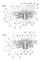
- the device 1 shown in Fig. 1 is connected to a pipe 2 with a Inner wall 4 connected, through the cavity a fluid medium can be. Samples of this medium can be prepared using the present Facility 1 can be taken. Of the pipeline 2 is only one in Fig. 1 Section shown.
- the present device 1 (Fig. 1) has a base 5, which in is essentially flat.
- This base 5 has a base body or lower part 6 and an upper part 7. Both the base part 6 and the base part 7 have a circular peripheral surface 3.
- the bottom 27 (Fig. 4) of the Base upper part 7 is essentially flat.
- the top 37 of the Base body 6 is also substantially flat.
- the upper part 7 of the Base 5 lies on its flat underside 27 on the flat top 37 of the Base part 6 on.
- the removed part of the wall of the Tube 2 represents a section of the jacket of a cylinder.
- the one in this Wise opening 28 in the wall of the tube 2 is limited by two straight edges 96 and 97, which are parallel to Extend the longitudinal axis of the tube 2, and through two arcuate edges 98 and 99, one of which is the mutually associated end of the rectilinear edges 96 and 97 connects together.
- the straight forward running opening edges 96 and 97 lie on the top 35 of the Base part 7 on.
- One of the curved opening edges 98 and 99, respectively is the circular circumferential surface 3 diametrically on two each other assigned opposite points of the upper base part 7.
- the Opening edges 96 to 99 are connected to the upper base part 7 in a fluid-tight manner.
- This is inside 4 of the tube 2 opening trough 100 extends in the upper base part 7 so that the valve 10 lying in the middle of the base body 6 lies below this trough 100 is located.
- the straight edges of the partially cylindrical trough 100 fall with the straight edges 96 and 97 of the pipe opening 28 together.
- the curved edges of the partially cylindrical trough 100 fall with the curved edges 98 and 99 of the pipe opening 28 together.
- a continuous receiving opening 8 is implemented in the base part 6, which is practically in the middle of the base part 6 and which has a circular inner wall.
- this opening 8 is a Valve 10 inserted.
- the inner wall of the receiving opening 8 is in itself known way executed so that the valve 10 by the Receiving opening 8 can not fall through.
- the valve 10 is a controlled valve and this is designed so that the fluid medium when closing the valve 10 from the inside thereof can be ousted.
- the valve 10 has a essentially rigid valve seat 11, the base body 12 in the illustrated Example has the shape of a disc with a circular circumference.
- the Wall of the receiving opening 8 in the base part 6 is a first expanded Section 38 of this opening 8, in which the outer edge of the disc-shaped base body 12 of the valve seat is used.
- the height of the circular projection 13 on the valve seat 11 is smaller than that Thickness of the base part 7 in this area of the base part 7. That is why the large area16 of the Projection 13 below the area of surface 35 located here the base part 7.
- An inlet or removal opening 15 is in the areal valve seat 11 executed, which are between the opposite Large areas 16 and 17 of the valve seat 11 or its base body 12 extends. It is understood that the present device also has several can have such removal openings 15.
- the inner wall of the removal opening 15 has the shape of a shell Cylinder.
- the removal opening 15 is in the base body 12 of the valve seat 11 eccentrically arranged and it is located in the area of said disc-like upper projection 13 on the valve seat 11.
- One of the Mouths 18 of the removal opening 15 are in the upper or outer Large area 16 of the disk-like projection 13.
- the other mouth 19 of the removal channel 15 lies in the inner or lower large area 17 of the valve body 11.
- the large area 16 of the disc-like projection 13 is the outer surface of the tube 2 fluid-tight assigned, in such a way that the hole 28 in the tube 2 with the Removal opening 15 in the valve seat 11 matches. So it can be fluid Medium through these openings 28 and 15 from inside the tube 2 in get inside the valve 10.
- the valve 10 further comprises a shut-off device 20, which consists of a is compliant material and which cooperate with the valve seat 11 can.
- the shut-off element 20 has a flat section 21, which has the shape of a disc with a circular peripheral surface.
- This areal section 21 of the shut-off element 20 has a diameter, which is comparable to the diameter of the valve seat 11. in the case shown is the diameter of the flat portion 21 of the Shut-off device 20 smaller than the diameter of the valve seat 11.
- a second paragraph or expanded section 25 of the receiving opening 8 which lies below the first expanded section 38 of this opening 8 and which has a smaller diameter than the first enlarged one Opening section 38.
- the outer edge portion 24 of the areal Section 21 of the shut-off device 20 lies in this second expanded Opening section 25 and it is between the edge of the on it lying body 12 of the valve seat 11 and the bottom of the second Paragraph 25 held in the receiving opening 8 of the base 5, for example by clamping said edge section 24.
- the flat section 21 of the shut-off element 20 is the inner one Large area 17 of the flat valve seat 11 assigned, the Central axes of these disks 12 and 21 coincide.
- the surface 22 of the areal section 21 of the shut-off element 20 lies on the underside 17 of the valve body 11 full or sealing when the device in unactuated position is (Fig. 2).
- the surface 22 of the areal section 21 of the shutoff member 20 also on the inner mouth 19 of the removal opening 15 in the valve seat 11, so that the areal section 21 of the shutoff member 20 also this Can close off the opening 15 sealingly.
- the shut-off device 20 also has an elongated extension 30, which of that large area 29 of the flat section 21 of the shut-off element 20 protrudes which faces away from the valve seat 11.
- the base body 31 of the Extension 30 has essentially the shape of a cylinder which over a of its base surfaces to the outer surface 29 of the flat section 21 the shut-off device 20 is connected.
- This extension 30 is with the Surface section 21 of the shut-off element 20 expediently in one piece.
- a channel 32 which is located in the axial area of the cylinder 31 is located in the surface section 21 of the shut-off device 20 continues. It is understood that the present device also has several Can have channels 32.
- the channel 32 has a cylindrical wall.
- the first or upper mouth 33 of this channel 32 lies in that large area 22 of the flat portion 21 of the shut-off device 20, which the Valve seat 11 faces.
- the second mouth 34 of the channel 32 is in the free end face of the extension 30. Since the inlet opening 15 is off-center is arranged and since the extension channel 32 on the contrary in the axial region A. of the valve 10, the inner mouth 33 of the extension channel 32 in addition to the removal opening 15 made in the valve seat 11.
- the present device further comprises an actuating device 40, which is attached to the base 5 of the device and which the extension 30 of the valve 10 is assigned.
- the actuator 40 is the Assigned to the outside of the extension 30 or it can be on the outside of the extension 30 act.
- the actuator 40 is among others executed so that they the extension 30 of the shut-off device 20 and the to this extension 30 adjoining parts of the areal section 21 of the shut-off device 20 from the lower surface 17 of the valve seat 11 can move away.
- the areal section 21 of the Shut-off device 20, which, as stated, is made of a flexible material, deformed by the actuating device 40 relative to the valve seat 11, that the lower mouth 19 of the inlet opening 15 is exposed. The fluid can then through the inlet opening 15 into an inside of the valve 10 in pass or flow in this way formed cavity 39.
- the actuating device 40 has a flat annular base body 41 on which is attached to the base 5 of the present device.
- the annular base body 41 of the actuating device 40 surrounds the extension 30 of the shut-off device 20, the diameter of the opening in Actuation ring 41 is at least as large as the outer diameter of the Extension 30.
- the height HR of the ring 41 is less than the height HF of the Extension 30.
- the ring 41 is arranged on the extension 30 so high that its upper large area 42 the lower large area 23 of the surface section 21 of the Barrier 20 touches.
- the outside of the extension 30 is provided with a drive plate 44, which surrounds the outer wall of the extension 30 and the outer Edge portion protrudes from the extension 30.
- the drive plate 44 is located below the bottom 43 of the ring 41.
- the outer diameter of the Driving plate 44 is larger than the inner diameter of the Actuating ring 41 so that the outer edge portion of the drive plate 44 strikes on the underside 43 of the actuating ring 41. If you do that Actuating ring 41 moves down, then the drive plate 44 because of the engagement with the underside 43 of the actuating ring 41 and thus also the Extension 30 also pulled down. This leads to that in FIG. 3 shown deformation of the flat portion 21 of the shut-off device 20, for Release of the internal mouth 19 of the inlet opening 15 and Formation of a cavity 39 in the valve 10, through which the inlet opening 15 is fluidly connected to the extension channel 32.
- the underside of the base body 6 of the device base 5 is with a provided relatively low annular projection 45, which itself is located below the valve seat 11.
- the inside diameter of this Ring projection 45 corresponds to the outer diameter of the actuating ring 41.
- the inner wall of the ring projection 45 has a thread 47 Mistake.
- the outer cylindrical peripheral wall of the actuation ring 41 is also provided with a thread 46, which with the thread 46 on Actuation ring 41 can work together.
- the actuating ring 41 with at least one handle 49 is a known one Provide design, which protrudes from the actuating ring 41.
- the Actuation ring 41 together with the handles 49 can also be used as a handwheel be designated. With the help of this handwheel, the ring projection 45 on the base 5 screwed actuation ring 41 can be rotated. This drives the actuating ring 41 into or out of the annular projection 45 Ring projection 45 out. Because of the aforementioned connection of the extension 30 the shut-off device 20 to the actuating ring 41, the shut-off device 20 in deformed in the manner described. This has among other things the formation of the mentioned cavity 39 in the valve 10 result.
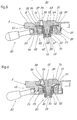
- the seat 51 of the present valve 50 comprises a first one Section 52, which is designed essentially as the seat 11 of the Valve 10 according to FIGS. 2 and 3.
- the seat 51 of the present valve 50 further includes a second section 53, which is designed as a conical elevation. This is from that large area 23 of the first, disk-like section 52 of the Valve seat 51, which faces the actuator 40.
- the the larger diameter of the base of the cone 53 is with connected to the disk-like section 52 of the valve seat 51 or integrally.
- the elevation 53 is located in the present valve 50 centrally and it is therefore adjacent to the inlet opening 55, which is also in the disc-like section 52 of the valve seat 51 in the already described manner is executed.
- the valve 10 further comprises a shut-off device 60, which also consists of a is compliant material and which cooperate with the valve seat 51 can.
- the shut-off element 60 has a flat section 61, which has the shape of a disc with a circular peripheral surface.
- the Edge portion 24 of the flat portion 61, which is in the area of Bottom of the second paragraph 25 is located in the receiving opening 8 is with an annular thickening 59 provided. In the case shown, this is Thickening 59 from the underside 29 of the flat section 61 from and the cross section of this thickening 59 is semicircular in the case shown.
- This thickening 59 is intended to hold the edge portion 24 of the areal section 61 between the base body of the valve seat 51 and contribute to the bottom of the second paragraph 25. It is understood that one such or similarly formed thickening 59 on or on the upper Large area 64 of the disk-shaped section 61 can be executed. Otherwise, this surface section 61 is similar to the surface section according to 2 and 3.
- the shut-off device 60 also has an elongated extension 70, which of that large area 29 of the areal section 61 of the shut-off element 60 protrudes which faces away from the valve seat 51.
- the base body 71 of the Extension 70 has essentially the shape of a cylinder which over a of its base surfaces to the outer surface 29 of the flat section 61 the shut-off device 60 is connected. This extension 70 is with the Surface section 61 of the shut-off element 60 expediently in one piece.
- a channel 62 is executed, which is in the axial area of the Cylinder 71 is located in surface section 61 of shut-off element 60 continues.
- the wall of the channel 62 is in the shape of a jacket of a cone.
- the dimensions of this conical extension channel 62 are selected such that that the conical elevation 53 of the valve seat 51 into the extension channel 62 can fit tightly with the conical shape. To improve this
- the tapered portion of the elevation 53 can be sealed with a additional ring seal 67 may be provided.
- the mouth 63 of the extension channel 62 is located in that large area 64 of the flat portion 61 of the shut-off member 60, which the valve seat 51st is facing.
- the mouth 65 of the smaller diameter Extension channel 62 lies in the free end face 66 of the extension 70.
- the actuating device 80 is the outside of the extension 70 assigned.
- the actuator 80 has a flat annular shape Base body 81, which on the base 5 of the present device is appropriate.
- the annular base body 81 of the actuating device 80 surrounds the extension 70 of the shut-off element 60, the diameter of the The opening in the actuating ring 81 is at least as large as the outer one Diameter of the extension 70.
- the underside of the base body 6 of the Furnishing base 5 is with a relatively low annular Provide projection 45 which surrounds the valve seat 51.
- the Inner diameter of this ring projection 45 corresponds to that Outside diameter of the actuation ring 81.
- a cylindrical sleeve 82 is on the outer surface of the extension 70 attached and in the outside of this sleeve 82 is a left-handed Internal thread 83 executed.
- a further left-hand thread 84 executed, which with thread 83 can work together on extension 70.
- the outer cylindrical The peripheral wall of the actuating ring 81 is a right-handed one Provided external thread 85.
- the inner wall of the ring projection 45 on Socket 5 is provided with a right-hand internal thread 86.
- the wall 56 has the Inlet opening 55 in the valve seat 51 has the shape of the shell of a cone.
- the the larger diameter mouth 57 of this inlet opening 55 is inside 39 of valve 50.
- the smaller diameter having mouth 58 of this inlet opening 55 lies in the upper or outer large area 16 of the seat 51 of the valve 50.
- auxiliary sealing body 75 is arranged in the inlet opening 55.
- the outer wall of this sealing body 75 has the shape of the shell of a cone, the dimensions and the orientation of this cone 75 are chosen in this way are that it fits sealingly into the inlet opening 55.
- the inside of the Valve 50 facing wider end portion 76 of auxiliary sealing body 75 rests the plan section 61 of the shutoff member 61.
- the sealing body 75 is like this long out that its opposite, narrower end portion 77 from the Inlet opening 55 even protrudes slightly when the valve 50 is in its unactuated position, or with the upper or smaller mouth 58th this opening 55 is at least flush.
- shut-off device 60 If the shut-off device 60 is in its unactuated position, then the flat section 61 of the shut-off element 61 presses the auxiliary sealing body 75 in the inlet opening 55 into it. Thereby the medium, which during the Operation of valve 50 flowed through inlet opening 55 when closing of valve 50 is displaced out of inlet opening 55 into cavity 2.
- the auxiliary closing element 75 When the valve is opened, the auxiliary closing element 75 is actuated by the pressure of the fluids located in the cavity 2 pressed down, creating an annular gap between the wall of the inlet opening and the wall of the auxiliary sealing body 75 is created, through which the fluid through the inlet opening and the interior of the Valve can flow.
- shut-off device closes the annular gap 72 and that the areal section 61 of the Shut-off device 60 moves against the valve seat 51. At the end presses the areal section 61 of the shut-off element 60 and the auxiliary closing element 75 into the interior of the inlet opening 55.
- the invention is in no way related to the foregoing, only by way of example described training limited. It is also a shut-off device with one dynamic seal conceivable without leaving the scope of the invention.
- the actuating means in various ways are also best for the person skilled in the art known. So are the shape and design of the handwheel in others equivalent variants conceivable.
- An often preferred execution includes a spring-closing load on the shut-off device and a so-called "Dead man's lever," which overcomes the spring force to open the valve. At the When the lever is released, the spring force closes the valve again.
- the opening one can also be carried out pneumatically or hydraulically.
- the materials of the three parts in contact with the product, i.e. the valve seat, the Shut-off device and the auxiliary closing device of the sampling valve are the Adapt the materials of the pipeline or the tank.
- the valve seat will preferably made of stainless steel or ceramic and the shut-off device can made of stainless steel or fluoroplastic such as Be PTFE.
- the Auxiliary locking device is preferably made in an elastic material such as Viton or perfluoroelastomer made. Materials, type of fastening as well Gasket type are in no way limited to this description. It Various known alternatives are available to the person skilled in the art.
- the Shut-off device 20 or 60 can be made of a metal, for example steel.
- the areal section 21 of such a shut-off device 20 or 60 is shown in FIG in such a case as a membrane made of the same metal, which with the extension 30 of this shut-off device 20 or 60 expediently is in one piece.
Landscapes
- Life Sciences & Earth Sciences (AREA)
- Hydrology & Water Resources (AREA)
- Physics & Mathematics (AREA)
- Health & Medical Sciences (AREA)
- Chemical & Material Sciences (AREA)
- Analytical Chemistry (AREA)
- Biochemistry (AREA)
- General Health & Medical Sciences (AREA)
- General Physics & Mathematics (AREA)
- Immunology (AREA)
- Pathology (AREA)
- Lift Valve (AREA)
- Mechanically-Actuated Valves (AREA)
Abstract
Description
Claims (10)
- Einrichtung zur Entnahme von fluiden Medien aus einem Hohlraum, insbesondere aus einer Rohrleitung (2) oder einem Behälter, mit einem Ventil, dadurch gekennzeichnet, dass das Ventil (10,50) so ausgeführt ist, dass das fluide Medium beim Schliessen des Ventils (10,50) aus dem Inneren des Ventils (10,50) verdrängt werden kann.
- Einrichtung nach Patentanspruch 1, dadurch gekennzeichnet, dass sie einen im wesentlichen flachen Sockel (5) aufweist und dass das Ventil (10,50) der einen Seite und die Hülle (2) des Hohlraumes der anderen Seite des Einrichtungssockels (5) zugeordnet sind.
- Einrichtung nach Patentanspruch 2, dadurch gekennzeichnet, dass das Ventil (10,50) ein gesteuertes Ventil ist, dass dieses Ventil (10,50) einen im wesentlichen steifen Ventilsitz (11,51) aufweist, dass dieser Ventilsitz dem Einrichtungssockel (5) zugeordnet ist, dass das Ventil (10,50) ferner ein Absperrorgan (20,60) aus einem nachgiebigen Material aufweist, welches mit dem Ventilsitz zusammenarbeiten kann und dass das Ventil (10,50) schliesslich eine Vorrichtung (40,80) aufweist, welche eine Verformung des nachgiebigen Absperrorgans gegenüber dem Ventilsitz ermöglicht.
- Einrichtung nach Patentanspruch 3, dadurch gekennzeichnet, dass der Ventilsitz (11,51) zumindest einen Abschnitt (12) aufweist, welcher im wesentlichen plan zw. flächenhaft ist, dass eine durchgehende Einlass- bzw. Entnahmeöffnug (15,55) im flächenhaften Abschnitt des Ventilsitzes ausgeführt ist, dass diese Einlassöffnung sich zwischen den einander gegenüberliegenden Grossflächen des Ventilsitzes erstreckt, dass das Absperrorgan (20,60), welches aus einem nachgiebigen Material ist, ebenfalls einen flächenhaften Abschnitt (21,61) aufweist und dass dieser flächenhafte Abschnitt des Absperrorgans einer der Grossflächen des flächenhaften Abschnittes (12,52) des Ventilsitzes zugeordnet ist, und zwar derart, dass der flächenhafte Abschnitt des Absperrorgans auf der in dieser Grossfläche liegenden Mündung der Entnahmeöffnung dichtend aufliegen kann
- Einrichtung nach Patentanspruch 4, dadurch gekennzeichnet, dass das Absperrorgan (20,60) einen länglichen Fortsatz (30,70) aufweist, welcher von jener Grossfläche des flächenhaften Abschnittes des Absperrorgans absteht, welche vom Ventilsitz abgewandt ist, dass in diesem Fortsatz ein Kanal (32,62) ausgeführt ist, dass die erste Mündung dieses Kanals in jener Grossfläche des flächenhaften Abschnittes des Absperrorgans liegt, welche dem Ventilsitz zugewandt ist, dass die zweite Mündung des Kanals in der freien Stirnfläche des Fortsatzes liegt und dass die Betätigungsvorrichtung (40,80) dem Fortsatz zugeordnet ist. (Fig. 2 bis 6)
- Einrichtung nach Patentanspruch 5, dadurch gekennzeichnet, dass der Kanal eine zylinderförmige Wand aufweist, dass die innenliegende Mündung des Kanals im Fortsatz neben der innenliegenden Mündung der Einlassöffnung im Ventilsitz angeordnet ist und dass die Betätigungsvorrichtung der Aussenseite des Fortsatzes zugeordnet ist. (Fig. 2und 3)
- Einrichtung nach Patentanspruch 5, dadurch gekennzeichnet, dass die Wand des Kanals die Form des Mantels eines Konusses aufweist, dass die den grösseren Durchmesser aufweisende Mündung des Fortsatzkanals in jener Grossfläche des flachen Abschnittes des Absperrorgans liegt, welche dem Ventilsitz zugewandt ist, dass die den kleineren Durchmesser aufweisende Mündung des Fortsatzkanals in der freien Stirnfläche des Fortsatzes liegt, dass die Betätigungsvorrichtung der Aussenseite des Fortsatzes zugeordnet ist, dass der Ventilsitz ferner eine konusförmige Erhebung aufweist, welche von jener Grossfläche des Ventilsitzes absteht, die dem Absperrorgan zugewandt ist, dass diese Erhebung neben der Einlassöffnung liegt und dass die Abmessungen der konusförmigen Erhebung derart gewählt sind, dass diese Erhebung in den Fortsatzkanal mit dem konusförmigen Verlauf dichtend passen kann. (Fig. 4 bis 6)
- Einrichtung nach Patentanspruch 5, dadurch gekennzeichnet, dass die Betätigungsvorrichtung (40,80) unter anderem so ausgeführt ist, dass sie den Fortsatz des Absperrorganes sowie die sich an diesen Fortsatz anschliessenden Partien des flächenhaften Abschnittes des Absperrorganes von der Oberfläche des Ventilsitzes weg bewegen kann.
- Einrichtung nach Patentanspruch 8, dadurch gekennzeichnet, dass die Betätigungsvorrichtung (40,80) einen ringförmigen Vorsprung (45) umfasst, welcher am Einrichtungssockel (5) angeformt ist und welcher den Ventilsitz (11,51) umgibt, dass die Innenseite dieses ringförmigen Vorsprungs (45) mit zumindest einem Gewinde versehen ist, dass die Betätigungsvorrichtung (40,80) ferner ein Betätigungsorgan aufweist, dass der Grundkörper (41,81) dieses Betätigungsorgans ringförmig ist, dass dieser Betätigungsring (41,81) ein Gewinde aufweist, welches mit dem Gewinde am Sockelring (45) zusammenarbeiten kann und dass der Betätigungsring (41,81) andererseits an den Fortsatz (30,70) des Absperrorganes angeschlossen ist
- Einrichtung nach Patentanspruch 4, dadurch gekennzeichnet, dass die Wand der Einlassöffnung (55) im Ventilsitz die Form des Mantels eines Konusses hat, dass die den grösseren Durchmesser aufweisende Mündung dieser Einlassöffnung im Inneren des Ventils (50) angeordnet ist, dass sich ein Hilfsdichtkörper (75) in der Einlassöffnung befindet, dass die Aussenwand dieses Dichtkörpers die Form des Mantels eines Konusses hat, dass die Abmessungen dieses Konusses so gewählt sind, dass er in die Einlassöffnung dichtend passen kann, und dass dieser Hilfsdichtkörper auf dem planen Abschnitt (61) des Absperrorgans (60) aufliegt.
Applications Claiming Priority (2)
| Application Number | Priority Date | Filing Date | Title |
|---|---|---|---|
| CH7242001 | 2001-04-20 | ||
| CH7242001A CH694999A5 (de) | 2001-04-20 | 2001-04-20 | Probenahmeventil zur Entnahme von fluessigen oder gasfoermigen Proben aus Leitungen oder Behaeltern. |
Publications (2)
| Publication Number | Publication Date |
|---|---|
| EP1253417A2 true EP1253417A2 (de) | 2002-10-30 |
| EP1253417A3 EP1253417A3 (de) | 2003-09-10 |
Family
ID=4531777
Family Applications (1)
| Application Number | Title | Priority Date | Filing Date |
|---|---|---|---|
| EP02405308A Withdrawn EP1253417A3 (de) | 2001-04-20 | 2002-04-16 | Probenahmeventil zur Entnahme von flüssigen oder gasförmigen Proben aus Leitungen oder Behältern |
Country Status (2)
| Country | Link |
|---|---|
| EP (1) | EP1253417A3 (de) |
| CH (1) | CH694999A5 (de) |
Cited By (2)
| Publication number | Priority date | Publication date | Assignee | Title |
|---|---|---|---|---|
| DE102007036612A1 (de) * | 2007-08-02 | 2009-02-05 | Dimatec Analysentechnik Gmbh | Einspritzport für Analysengeräte, Anordnung zur Betätigung eines Einspritzports sowie Analysengerät mit einem Einspritzport |
| DE102012200353A1 (de) * | 2012-01-11 | 2013-07-11 | Gemü Gebr. Müller Apparatebau Gmbh & Co. Kommanditgesellschaft | Mehrwegeventil, insbesondere Probenentnahmeventil |
Family Cites Families (8)
| Publication number | Priority date | Publication date | Assignee | Title |
|---|---|---|---|---|
| CH656601B (de) * | 1983-09-13 | 1986-07-15 | ||
| DE3546354C2 (de) * | 1985-12-30 | 1993-10-14 | Schleicher Leonhard | Probeentnahmeventil |
| US4836236A (en) * | 1987-07-29 | 1989-06-06 | Ladisch Thomas P | Flush sealing tank valve with diaphgram |
| ATE106513T1 (de) * | 1989-04-24 | 1994-06-15 | Keofitt As | Ventil zur musternahme. |
| DK247989D0 (da) * | 1989-05-22 | 1989-05-22 | Novo Nordisk As | Membranventil |
| US5277401A (en) * | 1991-04-17 | 1994-01-11 | Itt Corporation | Tank bottom diaphragm valve |
| JP2739063B2 (ja) * | 1995-04-05 | 1998-04-08 | 高砂電氣工業株式会社 | バルブ |
| DE20101218U1 (de) * | 2001-01-24 | 2001-06-13 | Harms, Gerald, Dipl.-Ing., 22609 Hamburg | Molchbares Ventil |
-
2001
- 2001-04-20 CH CH7242001A patent/CH694999A5/de not_active IP Right Cessation
-
2002
- 2002-04-16 EP EP02405308A patent/EP1253417A3/de not_active Withdrawn
Cited By (4)
| Publication number | Priority date | Publication date | Assignee | Title |
|---|---|---|---|---|
| DE102007036612A1 (de) * | 2007-08-02 | 2009-02-05 | Dimatec Analysentechnik Gmbh | Einspritzport für Analysengeräte, Anordnung zur Betätigung eines Einspritzports sowie Analysengerät mit einem Einspritzport |
| DE102012200353A1 (de) * | 2012-01-11 | 2013-07-11 | Gemü Gebr. Müller Apparatebau Gmbh & Co. Kommanditgesellschaft | Mehrwegeventil, insbesondere Probenentnahmeventil |
| WO2013104588A1 (de) | 2012-01-11 | 2013-07-18 | Gemü Gebr. Müller Apparatebau Gmbh & Co. Kommanditgesellschaft | Mehrwegeventil, insbesondere probenentnahmeventil |
| EP2802798A1 (de) * | 2012-01-11 | 2014-11-19 | Gemü Gebr. Müller Apparatebau Gmbh & Co. Kommanditgesellschaf | Mehrwegeventil, insbesondere probenentnahmeventil |
Also Published As
| Publication number | Publication date |
|---|---|
| CH694999A5 (de) | 2005-10-31 |
| EP1253417A3 (de) | 2003-09-10 |
Similar Documents
| Publication | Publication Date | Title |
|---|---|---|
| DE69213528T3 (de) | Keimfreie Ventilkonstruktion | |
| CH641886A5 (de) | Luftventil. | |
| DE69428365T2 (de) | Ventilkammerwand mit satellitenventilsitz | |
| DE3421653C2 (de) | Ventil | |
| DE69024768T2 (de) | Ventilanordnung | |
| DE2909046C2 (de) | Ventilanordnung für ein unter Druck stehendes fluides Medium | |
| CH656932A5 (de) | Absperrventil. | |
| DE2539000A1 (de) | Kugelventil | |
| DE69022095T2 (de) | Reingas-Ventil mit Metall-auf-Metall-Dichtung. | |
| EP1253417A2 (de) | Probenahmeventil zur Entnahme von flüssigen oder gasförmigen Proben aus Leitungen oder Behältern | |
| DE1147454B (de) | Absperrhahn | |
| DE1550468B2 (de) | Doppelsitzventil | |
| DE69013863T2 (de) | Druckempfindliches Ventil. | |
| WO2005033565A1 (de) | Verteilervorrichtung für ventile | |
| DE2901207A1 (de) | Absperrorgan | |
| DE1930733A1 (de) | Kugelhahn | |
| AT298185B (de) | Kugelhahn | |
| DE2754780A1 (de) | Ventilgehaeuse mit entfernbarer, in sich geschlossener ventileinheit | |
| CH678754A5 (en) | Valve arrangement for flow pipe - has valve plate and seating, with at least one sprung pipe | |
| DE69212014T2 (de) | Manuell und pneumatisch betätigbare Absperrarmatur | |
| DE3149116C2 (de) | Ventil zur Probeentnahme von flüssigen Medien | |
| DE240108C (de) | ||
| DE2011435A1 (de) | ||
| DE1550468C3 (de) | Doppelsitzventil | |
| DE2435328B2 (de) | Heizkörperverschraubung |
Legal Events
| Date | Code | Title | Description |
|---|---|---|---|
| PUAI | Public reference made under article 153(3) epc to a published international application that has entered the european phase |
Free format text: ORIGINAL CODE: 0009012 |
|
| AK | Designated contracting states |
Kind code of ref document: A2 Designated state(s): AT BE CH CY DE DK ES FI FR GB GR IE IT LI LU MC NL PT SE TR |
|
| AX | Request for extension of the european patent |
Free format text: AL;LT;LV;MK;RO;SI |
|
| PUAL | Search report despatched |
Free format text: ORIGINAL CODE: 0009013 |
|
| AK | Designated contracting states |
Kind code of ref document: A3 Designated state(s): AT BE CH CY DE DK ES FI FR GB GR IE IT LI LU MC NL PT SE TR |
|
| AX | Request for extension of the european patent |
Extension state: AL LT LV MK RO SI |
|
| 17P | Request for examination filed |
Effective date: 20040310 |
|
| AKX | Designation fees paid |
Designated state(s): AT BE CH CY DE DK ES FI FR GB GR IE IT LI LU MC NL PT SE TR |
|
| 17Q | First examination report despatched |
Effective date: 20080222 |
|
| STAA | Information on the status of an ep patent application or granted ep patent |
Free format text: STATUS: THE APPLICATION IS DEEMED TO BE WITHDRAWN |
|
| 18D | Application deemed to be withdrawn |
Effective date: 20071101 |