EP1253785A2 - Amélioration du standard d'un signal vidéo obtenu par balayage de trames et conversion d'un balayage entrelacé en un balayage séquentiel - Google Patents
Amélioration du standard d'un signal vidéo obtenu par balayage de trames et conversion d'un balayage entrelacé en un balayage séquentiel Download PDFInfo
- Publication number
- EP1253785A2 EP1253785A2 EP02252726A EP02252726A EP1253785A2 EP 1253785 A2 EP1253785 A2 EP 1253785A2 EP 02252726 A EP02252726 A EP 02252726A EP 02252726 A EP02252726 A EP 02252726A EP 1253785 A2 EP1253785 A2 EP 1253785A2
- Authority
- EP
- European Patent Office
- Prior art keywords
- signal
- standard
- alias
- components
- component
- Prior art date
- Legal status (The legal status is an assumption and is not a legal conclusion. Google has not performed a legal analysis and makes no representation as to the accuracy of the status listed.)
- Granted
Links
- 238000006243 chemical reaction Methods 0.000 title abstract description 11
- 238000000034 method Methods 0.000 claims abstract description 43
- 230000009466 transformation Effects 0.000 claims abstract description 22
- 230000008569 process Effects 0.000 claims abstract description 7
- 125000004122 cyclic group Chemical group 0.000 claims abstract description 4
- 230000000750 progressive effect Effects 0.000 claims description 4
- 230000001419 dependent effect Effects 0.000 claims description 3
- 238000005562 fading Methods 0.000 claims description 3
- 238000000844 transformation Methods 0.000 claims description 2
- 230000002238 attenuated effect Effects 0.000 abstract description 3
- 238000001228 spectrum Methods 0.000 description 7
- 230000004044 response Effects 0.000 description 6
- 238000010586 diagram Methods 0.000 description 5
- 238000001914 filtration Methods 0.000 description 5
- 230000000694 effects Effects 0.000 description 4
- 238000004891 communication Methods 0.000 description 3
- 238000012545 processing Methods 0.000 description 3
- 230000009471 action Effects 0.000 description 2
- 239000002131 composite material Substances 0.000 description 2
- 238000009499 grossing Methods 0.000 description 2
- 239000011159 matrix material Substances 0.000 description 2
- 238000012986 modification Methods 0.000 description 2
- 230000004048 modification Effects 0.000 description 2
- 230000002123 temporal effect Effects 0.000 description 2
- 230000007704 transition Effects 0.000 description 2
- 230000003044 adaptive effect Effects 0.000 description 1
- 238000013459 approach Methods 0.000 description 1
- 230000008901 benefit Effects 0.000 description 1
- 230000008859 change Effects 0.000 description 1
- 238000012886 linear function Methods 0.000 description 1
- 239000000463 material Substances 0.000 description 1
- 238000011160 research Methods 0.000 description 1
- 238000012360 testing method Methods 0.000 description 1
Images

Classifications
-
- G—PHYSICS
- G09—EDUCATION; CRYPTOGRAPHY; DISPLAY; ADVERTISING; SEALS
- G09G—ARRANGEMENTS OR CIRCUITS FOR CONTROL OF INDICATING DEVICES USING STATIC MEANS TO PRESENT VARIABLE INFORMATION
- G09G3/00—Control arrangements or circuits, of interest only in connection with visual indicators other than cathode-ray tubes
-
- H—ELECTRICITY
- H04—ELECTRIC COMMUNICATION TECHNIQUE
- H04N—PICTORIAL COMMUNICATION, e.g. TELEVISION
- H04N19/00—Methods or arrangements for coding, decoding, compressing or decompressing digital video signals
- H04N19/50—Methods or arrangements for coding, decoding, compressing or decompressing digital video signals using predictive coding
- H04N19/59—Methods or arrangements for coding, decoding, compressing or decompressing digital video signals using predictive coding involving spatial sub-sampling or interpolation, e.g. alteration of picture size or resolution
-
- H—ELECTRICITY
- H04—ELECTRIC COMMUNICATION TECHNIQUE
- H04N—PICTORIAL COMMUNICATION, e.g. TELEVISION
- H04N7/00—Television systems
- H04N7/01—Conversion of standards, e.g. involving analogue television standards or digital television standards processed at pixel level
- H04N7/0117—Conversion of standards, e.g. involving analogue television standards or digital television standards processed at pixel level involving conversion of the spatial resolution of the incoming video signal
- H04N7/012—Conversion between an interlaced and a progressive signal
-
- G—PHYSICS
- G09—EDUCATION; CRYPTOGRAPHY; DISPLAY; ADVERTISING; SEALS
- G09G—ARRANGEMENTS OR CIRCUITS FOR CONTROL OF INDICATING DEVICES USING STATIC MEANS TO PRESENT VARIABLE INFORMATION
- G09G2310/00—Command of the display device
- G09G2310/02—Addressing, scanning or driving the display screen or processing steps related thereto
- G09G2310/0229—De-interlacing
-
- G—PHYSICS
- G09—EDUCATION; CRYPTOGRAPHY; DISPLAY; ADVERTISING; SEALS
- G09G—ARRANGEMENTS OR CIRCUITS FOR CONTROL OF INDICATING DEVICES USING STATIC MEANS TO PRESENT VARIABLE INFORMATION
- G09G5/00—Control arrangements or circuits for visual indicators common to cathode-ray tube indicators and other visual indicators
- G09G5/003—Details of a display terminal, the details relating to the control arrangement of the display terminal and to the interfaces thereto
- G09G5/006—Details of the interface to the display terminal
Definitions
- This invention relates to a method of and apparatus for increasing the standard of a raster-scanned video signal, and particularly though not exclusively to a method of and apparatus for converting from interlaced scan to sequential scan format.
- Sequential scan format is also known as a non-interlaced scan or as a progressive scan.
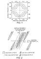
- FIG. 1 is a 'topographical' view illustrating the response for a range of temporal frequencies ⁇ 25Hz and a range of vertical frequencies ⁇ 288 cycles per active picture height (c/aph).
- c/aph active picture height
- Space-time/frequency domain transformations that is space-time domain to/from frequency domain transforms, such as the Fourier transform
- frequency domain transforms such as the Fourier transform
- OFDM orthogonal frequency-division multiplex
- DAB digital audio broadcasting
- DVB-T digital video broadcasting - terrestrial
- Phase correlation motion estimation also uses Fourier transforms, though not in the signal path. Two-dimensional filtering of still images in the Fourier domain is discussed in "An introduction to digital image processing" by Wayne Niblack, Prentice-Hall, 1986, ISBN 0-13-480674-3, Sections 4.2 to 4.4, pages 103 to 112.
- Space-time/frequency transforms have been proposed for decoding composite video signals, see for example United States Patent US-A-5,621,477 (Demmer) which describes the use of a Hadamard transform, or alternatively a Fourier transform, for decoding a composite video signal.
- United Kingdom Patent Specification GB-A-2 243 514 (Weston) describes generating interlaced video signals by interpolation
- United States Patent US-A-5,845,015 describes a method of resizing an image using the discrete cosine transform (DCT) using the convolution-multiplication properties of the DCT applied to non-overlapping blocks of the image
- International Patent Application WO 01/24532 A1 (Azadegan et al) describes DCT domain conversion of a video signal to a lower definition signal by replacing an identity matrix with a diagonal matrix in a DCT domain.
- This embodiment takes the form of an interlace-to-sequential video standards converter which receives an interlaced raster-scanned input signal at an input standard.
- a deinterlacer inserts zero values into the signal so as to increase the standard to a required output standard.
- the output standard signal is formed into data blocks which in turn are subjected to a Fourier transformation to produce a transformed signal containing a plurality of components each having a value.
- the components of the transformed signal are assigned as signal or alias components, the assignment being made in dependence upon the component values.
- the component values which are assigned as signal components are then subjected to an inverse Fourier transformation to provide at least the additional signal values required to increase the input signal to the output standard.
- Other types of up-conversion are possible, such as increasing the line standard of an existing sequential signal.
- the assignment operation proceeds by a cyclic process of growing signal and alias regions.
- assigner assigns a component as 'signal', it assigns that component's alias as 'alias'. Initially the assigner assigns the "zero frequency" component (or a region around it) to 'signal' and the alias of that component (or region) to 'alias'. The 'signal' region is grown by considering all unassigned neighbour components and adding the one with greater magnitude. Its alias is added to the 'alias' region. Any component which is its own alias is assigned to a special 'border' class.
- those in the 'alias' region are set to zero, those in the 'border' class are attenuated by a factor of two, and those in the 'signal' region are not modified.
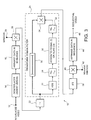
- FIG. 3 is a block diagram of an interlace-to-sequential converter embodying the invention.
- the interlace-to-sequential converter may be used with video signals in any of a number of ways, for example in television studio equipment, for signal processing at a broadcast transmitter, or with a video display, for example a flat panel display such as a plasma display device.
- the converter could also, for example, be used to produce a relatively high quality still picture from one instant of a video signal, for example the converter could be produced in the form of an expansion card for a personal computer.
- the interlace-to-sequential converter 10 illustrated is seen to have an input 12 for receiving an interlaced video input signal which is a raster-scanned signal at an input standard, that is having a predetermined number of lines arranged in each of a plurality of successive interlaced fields.
- a deinterlacer or inserter 14 Connected to the input 12 is a deinterlacer or inserter 14 which converts the input signal into a signal at the required output standard by simply inserting zeros into the signal at those points which are present in the output standard but not in the input standard. That is, the deinterlacer 14 in this embodiment inserts a line of zeros between each pair of input lines.
- the signal now has the form of a sequential (or progressive) signal but with alternate lines consisting solely of zeros.
- a data arranger 16 which arranges the data into blocks. These blocks are three dimensional, that is they may consist of 32 samples by 32 lines by 8 fields. The blocks may, and indeed preferably do overlap. Block sizes of 4-128 samples by 4-128 lines by 2-32 fields may be considered; with 8 fields a minimum block size of 16 by 16 is preferred and 64 by 64 is better. The overlap is preferably complete, in that the blocks are spaced at 50% of the block size.
- the output of the data arranger 16 is applied to a circuit 18 where the blocks are successively multiplied by a windowing function, which is any suitable symmetric function allowing a cross-fade from one block to the next so as to avoid sharp transitions at the block edges.
- the windowing function is applied via an input 20.
- the blocks are now applied to a Fourier transform circuit 22, conveniently implemented as a fast Fourier transform or FFT.
- FFT effects a space-time/frequency transformation from the space-time domain to the frequency domain.
- the signal After the Fourier transformation, the signal now consists of successive three-dimensional blocks of frequencies, which can be considered rather like a three-dimensional version of Figure 1.
- the thus-transformed signal is now applied to a transform domain filter 24 which filters the block of frequency components so as to attenuate selected ones of the components in dependence upon the component values. This is achieved by allocating each component of the transformed signal either as a signal (wanted) component or as an alias (unwanted) component.
- the transform domain filter 24 is constructed as follows.
- the FFT produces a complex output from its real input, and so to the output of the FFT 22 is connected an absolute value circuit 26 which takes the modulus of the complex signal applied to it, i.e. the square root of the sum of the squares of the real and imaginary components.
- the output of the absolute value circuit is applied, through an optional 'hole-filling' filter 28, to an assigning circuit or assigner 30. This assigns each component either as a signal component or as an alias component in a manner described below.
- the output of the assigning circuit will be a one or a zero for each input component indicating whether that component is respectively a signal component or an alias component, except for some 'border' components which may take the value of a half (see below). It will be remembered that the components are here frequency components due to the action of the transform circuit 22.
- the output of the assigning circuit is applied through another optional 'smoothing' filter 32 to one input of a multiplier 34. Either or both of the filters 28,32 can be omitted.
- the other input of the multiplier 34 receives the signal components themselves from the Fourier transform circuit 22, subject to delay in a compensating delay 36 to compensate for the total delay in the elements 26 to 32, so that the frequency component value and the indication of whether it is signal or alias are co-timed at the multiplier 34.
- the multiplier 34 will thus pass those components which are signal components, and attenuate the frequency components which are identified as alias components.
- the signal from the multiplier 34 in the transform domain filter 24 is first applied to an inverse Fourier transform (IFT) circuit 38.
- IFT inverse Fourier transform
- the circuit 38 may take the form of an inverse fast Fourier transform (IFFT).
- IFFT inverse fast Fourier transform
- the output of the IFT circuit 38 is applied to an inverse windowing circuit 40 which receives a windowing function at an input 42 is the inverse of the windowing function at input 20.
- the windowing circuit 40 provides for cross-fading between blocks.
- circuit 40 is applied to a data arranger 44 which takes the blockwise information which has been generated by the IFT circuit 38 and places it in proper sequence for a raster-scanned output signal. In this case that is a sequential signal.
- the transform domain filter operates to attenuate those parts of the spectrum that contain aliases of the signal while retaining those parts that contain the signal itself. This can be considered as dividing, or segmenting, the 3-D transform domain into two equal-sized regions, one centred on (0 c/aph, 0Hz) and the other centred on ( ⁇ 288 c/aph, ⁇ 25Hz). In summary, in the preferred embodiment this is done by a region growing process. Starting at (0 c/aph, 0Hz) the largest magnitude adjacent sample is selected and assigned or allocated to the 'signal' region, and its alias is allocated to the unwanted or 'alias' region. When all the samples have been assigned, those in the 'alias' region are set to zero before the inverse transform is computed.
- the procedure starts at 50 and passes to step 52 where the zero or centre frequency of the block is first assigned as 'signal'.
- Each component in the block has a respective alias component.
- the alias component is the component in the block which is offset from the signal component by 288 c/aph, 25Hz, that is (1 ⁇ 2L, 1 ⁇ 2F) where the block contains ⁇ L lines and ⁇ F fields.
- the alias of the zero frequency is assigned as 'alias', that is an unwanted component.
- step 54 in which the nearest neighbours of the zero frequency, which has been assigned as 'signal', are identified. There are 26 of these at this stage.
- step 56 in which these 26 nearest neighbours are tested and the one which has the greatest amplitude is selected. This nearest neighbour is now also assigned as 'signal', and its alias is assigned as 'alias'.
- step 56 a test is made to see whether all the components have been assigned. Here clearly they have not, and the procedure re-circulates to step 54.
- step 54 the components which have been assigned as 'signal' will form a unitary region, and the nearest neighbours of this region are identified. In practice this simply means that the nearest neighbour which was identified as 'signal' on the previous cycle is replaced by its unassigned nearest neighbours. The number of such neighbours will change as the 'signal' region changes shape.
- step 56 a selection of the largest of this group of neighbours is made and this is also assigned as 'signal', and its alias is assigned as 'alias'. This cycle continues with the region of 'signal' components growing adaptively on each cycle. The way it grows depends on the relative amplitudes of the components and is thus signal-dependent.
- 'signal' or 'alias' to a component, in fact, means storing a 1 or a 0 respectively in relation to that component. Alias component values will then be completely attenuated, viz. reduced to zero, in the multiplier 34.
- step 60 The point will come when the region of 'signal' components starts to meet the region of 'alias' components, and the number of unassigned components in the nearest neighbours group will start to reduce. Eventually all the components will have been allocated, and the output of step 58 will be YES, and the procedure ends at step 60.
- the 'alias' components will also form a unitary region in infinite three-dimensional space, but it will not look like that due to the finite size of the data block.
- each data block there may be components which are exactly half-way between the centre and the corners of the block. These points are their own alias and need special treatment. They are assigned a value of 0.5 (one half). This is done so that the overall filtering function of the transform domain filter is that of a Nyquist filter, and this is desirable because that ensures that all the original input lines are left unmodified. This 0.5 assignment, when necessary, requires an extra step (not shown) in the flowchart of Figure 4.
- the assumption can be made that there is a central region, not just the single central component, which will always be 'signal'.
- the shape of this component can be determined empirically by evaluating a large number of samples of the type of signal to be processed.
- the amplitudes which are stored for the nearest neighbours may be subject to a prefiltering operation prior to the selection of the largest value. That is, each component value may be replaced by a weighted average of that value with a contribution from each of the surrounding values. This smoothes out the values used in the region-growing operation.
- the selected 'signal' components are all used at equal magnitude and the 'alias' components are all discarded.
- This has the effect of a "sharp cut” filter which may produce undesirable "ringing" in the output image.
- This effect may be reduced by use of the optional smoothing filter 32 to apply a suitable transition shape to the control signal input to the multiplier 34.
- the method described divides the frequency components into two equal-sized regions, the 'signal' region and the 'alias' region respectively, which produces a Nyquist filter.
- it may be preferred to have an unequal division e.g. to "soften” the output image by reducing the size of the 'signal' region. This may be achieved by giving filter 32 a non-linear function, such as a rank-order filter that selects the minimum value from those surrounding the value under consideration.
- the output signal will comprise the lines of the input signal together with an equal number of new lines in between the old, input lines.
- the old, input lines should be unchanged.
- the deinterlacer 14 inserts a line of zeros between each pair of input lines. It would, in principle, be possible to use any constant value for the inserted lines, but the sequential video output will then have a constant offset, which would need to be subtracted. There could, however, be an advantage in choosing an offset value that minimises the amplitude of the 'zero frequency' sample in Fourier space.
- Figure 3 is shown as a hardware diagram with the components shown as hardware components, but the converter may, in practice, be largely or fully implemented in software. In this case Figure 3 should be regarded as more in the nature of a flowchart.
- the preferred and illustrated embodiment of the invention uses a region-growing process. However, this may not be the only practical way of assigning the components as signal or alias, and another assignment method could be employed.
- an interlace-to-sequential scan conversion is provided.
- the invention is, however, applicable to other forms of upconversion, for example, upconverting a sequential signal to a higher standard with an increased number of lines per field.
- Another example of its use might be in field rate up-conversion, for example from 50 Hz to 100 Hz.
Landscapes
- Engineering & Computer Science (AREA)
- Physics & Mathematics (AREA)
- Computer Hardware Design (AREA)
- General Physics & Mathematics (AREA)
- Theoretical Computer Science (AREA)
- Computer Graphics (AREA)
- Multimedia (AREA)
- Signal Processing (AREA)
- Television Systems (AREA)
- Color Television Systems (AREA)
Applications Claiming Priority (2)
| Application Number | Priority Date | Filing Date | Title |
|---|---|---|---|
| GB0110292 | 2001-04-26 | ||
| GB0110292A GB2374997B (en) | 2001-04-26 | 2001-04-26 | Increasing the standard of a raster-scanned video signal |
Publications (3)
| Publication Number | Publication Date |
|---|---|
| EP1253785A2 true EP1253785A2 (fr) | 2002-10-30 |
| EP1253785A3 EP1253785A3 (fr) | 2004-07-28 |
| EP1253785B1 EP1253785B1 (fr) | 2010-07-07 |
Family
ID=9913534
Family Applications (1)
| Application Number | Title | Priority Date | Filing Date |
|---|---|---|---|
| EP02252726A Expired - Lifetime EP1253785B1 (fr) | 2001-04-26 | 2002-04-17 | Amélioration du standard d'un signal vidéo obtenu par balayage de trames et conversion d'un balayage entrelacé en un balayage séquentiel |
Country Status (3)
| Country | Link |
|---|---|
| EP (1) | EP1253785B1 (fr) |
| DE (1) | DE60236905D1 (fr) |
| GB (1) | GB2374997B (fr) |
Cited By (1)
| Publication number | Priority date | Publication date | Assignee | Title |
|---|---|---|---|---|
| EP1931136A1 (fr) * | 2006-12-08 | 2008-06-11 | Matsushita Electric Industrial Co., Ltd. | Algorithme de combinaison de lignes basé sur les blocs pour le désentrelacement |
Citations (6)
| Publication number | Priority date | Publication date | Assignee | Title |
|---|---|---|---|---|
| GB2243514A (en) | 1990-02-09 | 1991-10-30 | British Broadcasting Corp | Generation of interlaced television signals by interpolation |
| EP0702488A1 (fr) | 1994-09-19 | 1996-03-20 | France Telecom | Procédé et dispositif de conversion d'une image numérique de télévision du format entrelacé au format progressif et leurs applications |
| US5621477A (en) | 1994-07-01 | 1997-04-15 | Harris Corp | Digital decoder and method for decoding composite video signals |
| US5845015A (en) | 1995-10-12 | 1998-12-01 | Sarnoff Corporation | Method and apparatus for resizing images using the discrete cosine transform |
| US6124893A (en) | 1998-04-29 | 2000-09-26 | Stapleton; John J. | Versatile video transformation device |
| WO2001024532A1 (fr) | 1999-09-30 | 2001-04-05 | Conexant Systems, Inc. | Conversion de domaine tcd d'un signal video en un signal a definition reduite |
Family Cites Families (1)
| Publication number | Priority date | Publication date | Assignee | Title |
|---|---|---|---|---|
| AU5691294A (en) * | 1992-12-18 | 1994-07-19 | Maher A. Sid-Ahmed | Real-time television image pixel multiplication methods and apparatus |
-
2001
- 2001-04-26 GB GB0110292A patent/GB2374997B/en not_active Expired - Fee Related
-
2002
- 2002-04-17 DE DE60236905T patent/DE60236905D1/de not_active Expired - Lifetime
- 2002-04-17 EP EP02252726A patent/EP1253785B1/fr not_active Expired - Lifetime
Patent Citations (6)
| Publication number | Priority date | Publication date | Assignee | Title |
|---|---|---|---|---|
| GB2243514A (en) | 1990-02-09 | 1991-10-30 | British Broadcasting Corp | Generation of interlaced television signals by interpolation |
| US5621477A (en) | 1994-07-01 | 1997-04-15 | Harris Corp | Digital decoder and method for decoding composite video signals |
| EP0702488A1 (fr) | 1994-09-19 | 1996-03-20 | France Telecom | Procédé et dispositif de conversion d'une image numérique de télévision du format entrelacé au format progressif et leurs applications |
| US5845015A (en) | 1995-10-12 | 1998-12-01 | Sarnoff Corporation | Method and apparatus for resizing images using the discrete cosine transform |
| US6124893A (en) | 1998-04-29 | 2000-09-26 | Stapleton; John J. | Versatile video transformation device |
| WO2001024532A1 (fr) | 1999-09-30 | 2001-04-05 | Conexant Systems, Inc. | Conversion de domaine tcd d'un signal video en un signal a definition reduite |
Cited By (1)
| Publication number | Priority date | Publication date | Assignee | Title |
|---|---|---|---|---|
| EP1931136A1 (fr) * | 2006-12-08 | 2008-06-11 | Matsushita Electric Industrial Co., Ltd. | Algorithme de combinaison de lignes basé sur les blocs pour le désentrelacement |
Also Published As
| Publication number | Publication date |
|---|---|
| GB2374997A (en) | 2002-10-30 |
| GB2374997B (en) | 2005-04-13 |
| GB0110292D0 (en) | 2001-06-20 |
| EP1253785A3 (fr) | 2004-07-28 |
| DE60236905D1 (de) | 2010-08-19 |
| EP1253785B1 (fr) | 2010-07-07 |
Similar Documents
| Publication | Publication Date | Title |
|---|---|---|
| US5940141A (en) | Nonlinear vertical bandwidth expansion of video signals | |
| Bellers et al. | De-interlacing: A key technology for scan rate conversion | |
| US5708476A (en) | System and method for inserting and recovering a data signal for transmission with a video signal | |
| CN1029904C (zh) | 使用消除信号畸变的映像的伪随机序列的发送/接收设备 | |
| US4602273A (en) | Interpolated progressive-scan television display with line-crawl artifact filtration | |
| JPH1070708A (ja) | 非インターレース化装置 | |
| Fukinuki et al. | Extended definition TV fully compatible with existing standards | |
| US5067018A (en) | Frequency-division multiplexing arrangement for preventing interference between a main television signal and a helper signal thereof | |
| JP2003500944A (ja) | インターレースされた画像信号からプログレッシブ走査された画像信号への変換方法 | |
| JP2865758B2 (ja) | ビデオ信号の成分を合成および分離する装置 | |
| EP0348163A2 (fr) | Système de transmission de télévision compatible avec un chemin de préaccentuation séparé à l'intérieur d'un canal unique | |
| JPH0394592A (ja) | 視覚的にマスクされた補強信号を発生する方法 | |
| NL8501633A (nl) | Televisieoverdrachtssysteem. | |
| EP1332471A2 (fr) | Compensation de mouvement d'images | |
| EP1253785B1 (fr) | Amélioration du standard d'un signal vidéo obtenu par balayage de trames et conversion d'un balayage entrelacé en un balayage séquentiel | |
| CA2152660A1 (fr) | Appareil et methode de decodage numerique de signaux video | |
| US5227879A (en) | Apparatus for transmitting an extended definition TV signal having compatibility with a conventional TV system | |
| EP0496451B1 (fr) | Processeur de signal non-linéaire | |
| US5068725A (en) | Band compressing/restoring apparatus | |
| WO1992008318A1 (fr) | Appareil de codage de signaux televisuels | |
| EP1175102B1 (fr) | Filtrage sélectif de chrominance à utiliser dans le décodage de signal vidéo couleur | |
| JPH01501832A (ja) | テレビジョン型ビデオ信号の符号化装置およびビデオ信号処理装置 | |
| EP0549238B1 (fr) | Système de transmission et de réception pour le codage à haute efficacité d'un signal composite de télévision | |
| KR100518159B1 (ko) | 순차 화상의 시퀀스를 발생시키기 위한 방법 및 회로 장치 | |
| EP0112499A2 (fr) | Procédé et appareil pour le codage à 2 niveaux de signaux vidéo en couleur |
Legal Events
| Date | Code | Title | Description |
|---|---|---|---|
| PUAI | Public reference made under article 153(3) epc to a published international application that has entered the european phase |
Free format text: ORIGINAL CODE: 0009012 |
|
| AK | Designated contracting states |
Kind code of ref document: A2 Designated state(s): AT BE CH CY DE DK ES FI FR GB GR IE IT LI LU MC NL PT SE TR |
|
| AX | Request for extension of the european patent |
Free format text: AL;LT;LV;MK;RO;SI |
|
| PUAL | Search report despatched |
Free format text: ORIGINAL CODE: 0009013 |
|
| AK | Designated contracting states |
Kind code of ref document: A3 Designated state(s): AT BE CH CY DE DK ES FI FR GB GR IE IT LI LU MC NL PT SE TR |
|
| AX | Request for extension of the european patent |
Extension state: AL LT LV MK RO SI |
|
| 17P | Request for examination filed |
Effective date: 20050128 |
|
| AKX | Designation fees paid |
Designated state(s): BE DE FR GB IT |
|
| 17Q | First examination report despatched |
Effective date: 20081023 |
|
| RBV | Designated contracting states (corrected) |
Designated state(s): BE DE FR IT |
|
| GRAP | Despatch of communication of intention to grant a patent |
Free format text: ORIGINAL CODE: EPIDOSNIGR1 |
|
| GRAS | Grant fee paid |
Free format text: ORIGINAL CODE: EPIDOSNIGR3 |
|
| GRAA | (expected) grant |
Free format text: ORIGINAL CODE: 0009210 |
|
| AK | Designated contracting states |
Kind code of ref document: B1 Designated state(s): BE DE FR IT |
|
| REF | Corresponds to: |
Ref document number: 60236905 Country of ref document: DE Date of ref document: 20100819 Kind code of ref document: P |
|
| PG25 | Lapsed in a contracting state [announced via postgrant information from national office to epo] |
Ref country code: BE Free format text: LAPSE BECAUSE OF FAILURE TO SUBMIT A TRANSLATION OF THE DESCRIPTION OR TO PAY THE FEE WITHIN THE PRESCRIBED TIME-LIMIT Effective date: 20100707 |
|
| PLBE | No opposition filed within time limit |
Free format text: ORIGINAL CODE: 0009261 |
|
| STAA | Information on the status of an ep patent application or granted ep patent |
Free format text: STATUS: NO OPPOSITION FILED WITHIN TIME LIMIT |
|
| PG25 | Lapsed in a contracting state [announced via postgrant information from national office to epo] |
Ref country code: IT Free format text: LAPSE BECAUSE OF FAILURE TO SUBMIT A TRANSLATION OF THE DESCRIPTION OR TO PAY THE FEE WITHIN THE PRESCRIBED TIME-LIMIT Effective date: 20100707 |
|
| 26N | No opposition filed |
Effective date: 20110408 |
|
| REG | Reference to a national code |
Ref country code: DE Ref legal event code: R097 Ref document number: 60236905 Country of ref document: DE Effective date: 20110408 |
|
| PGFP | Annual fee paid to national office [announced via postgrant information from national office to epo] |
Ref country code: DE Payment date: 20130703 Year of fee payment: 12 |
|
| PGFP | Annual fee paid to national office [announced via postgrant information from national office to epo] |
Ref country code: FR Payment date: 20130724 Year of fee payment: 12 |
|
| REG | Reference to a national code |
Ref country code: DE Ref legal event code: R119 Ref document number: 60236905 Country of ref document: DE |
|
| REG | Reference to a national code |
Ref country code: DE Ref legal event code: R119 Ref document number: 60236905 Country of ref document: DE Effective date: 20141101 |
|
| REG | Reference to a national code |
Ref country code: FR Ref legal event code: ST Effective date: 20141231 |
|
| PG25 | Lapsed in a contracting state [announced via postgrant information from national office to epo] |
Ref country code: DE Free format text: LAPSE BECAUSE OF NON-PAYMENT OF DUE FEES Effective date: 20141101 |
|
| PG25 | Lapsed in a contracting state [announced via postgrant information from national office to epo] |
Ref country code: FR Free format text: LAPSE BECAUSE OF NON-PAYMENT OF DUE FEES Effective date: 20140430 |