EP1254006B1 - Procede de commande/regulation du processus d'estampage ainsi que dispositif d'entrainement et de commande d'outils de moulage par injection - Google Patents
Procede de commande/regulation du processus d'estampage ainsi que dispositif d'entrainement et de commande d'outils de moulage par injection Download PDFInfo
- Publication number
- EP1254006B1 EP1254006B1 EP01902230A EP01902230A EP1254006B1 EP 1254006 B1 EP1254006 B1 EP 1254006B1 EP 01902230 A EP01902230 A EP 01902230A EP 01902230 A EP01902230 A EP 01902230A EP 1254006 B1 EP1254006 B1 EP 1254006B1
- Authority
- EP
- European Patent Office
- Prior art keywords
- drive
- embossing
- force
- mould half
- control
- Prior art date
- Legal status (The legal status is an assumption and is not a legal conclusion. Google has not performed a legal analysis and makes no representation as to the accuracy of the status listed.)
- Expired - Lifetime
Links
Images


Classifications
-
- B—PERFORMING OPERATIONS; TRANSPORTING
- B29—WORKING OF PLASTICS; WORKING OF SUBSTANCES IN A PLASTIC STATE IN GENERAL
- B29C—SHAPING OR JOINING OF PLASTICS; SHAPING OF MATERIAL IN A PLASTIC STATE, NOT OTHERWISE PROVIDED FOR; AFTER-TREATMENT OF THE SHAPED PRODUCTS, e.g. REPAIRING
- B29C45/00—Injection moulding, i.e. forcing the required volume of moulding material through a nozzle into a closed mould; Apparatus therefor
- B29C45/17—Component parts, details or accessories; Auxiliary operations
- B29C45/46—Means for plasticising or homogenising the moulding material or forcing it into the mould
- B29C45/56—Means for plasticising or homogenising the moulding material or forcing it into the mould using mould parts movable during or after injection, e.g. injection-compression moulding
- B29C45/561—Injection-compression moulding
- B29C2045/5615—Compression stroke, e.g. length thereof
- B29C2045/562—Velocity profiles of the compression stroke
-
- B—PERFORMING OPERATIONS; TRANSPORTING
- B29—WORKING OF PLASTICS; WORKING OF SUBSTANCES IN A PLASTIC STATE IN GENERAL
- B29C—SHAPING OR JOINING OF PLASTICS; SHAPING OF MATERIAL IN A PLASTIC STATE, NOT OTHERWISE PROVIDED FOR; AFTER-TREATMENT OF THE SHAPED PRODUCTS, e.g. REPAIRING
- B29C45/00—Injection moulding, i.e. forcing the required volume of moulding material through a nozzle into a closed mould; Apparatus therefor
- B29C45/17—Component parts, details or accessories; Auxiliary operations
- B29C45/46—Means for plasticising or homogenising the moulding material or forcing it into the mould
- B29C45/56—Means for plasticising or homogenising the moulding material or forcing it into the mould using mould parts movable during or after injection, e.g. injection-compression moulding
- B29C45/561—Injection-compression moulding
- B29C2045/566—Reducing compression pressure during cooling of the moulded material
-
- B—PERFORMING OPERATIONS; TRANSPORTING
- B29—WORKING OF PLASTICS; WORKING OF SUBSTANCES IN A PLASTIC STATE IN GENERAL
- B29C—SHAPING OR JOINING OF PLASTICS; SHAPING OF MATERIAL IN A PLASTIC STATE, NOT OTHERWISE PROVIDED FOR; AFTER-TREATMENT OF THE SHAPED PRODUCTS, e.g. REPAIRING
- B29C2945/00—Indexing scheme relating to injection moulding, i.e. forcing the required volume of moulding material through a nozzle into a closed mould
- B29C2945/76—Measuring, controlling or regulating
- B29C2945/76003—Measured parameter
- B29C2945/76013—Force
-
- B—PERFORMING OPERATIONS; TRANSPORTING
- B29—WORKING OF PLASTICS; WORKING OF SUBSTANCES IN A PLASTIC STATE IN GENERAL
- B29C—SHAPING OR JOINING OF PLASTICS; SHAPING OF MATERIAL IN A PLASTIC STATE, NOT OTHERWISE PROVIDED FOR; AFTER-TREATMENT OF THE SHAPED PRODUCTS, e.g. REPAIRING
- B29C2945/00—Indexing scheme relating to injection moulding, i.e. forcing the required volume of moulding material through a nozzle into a closed mould
- B29C2945/76—Measuring, controlling or regulating
- B29C2945/76003—Measured parameter
- B29C2945/7602—Torque
-
- B—PERFORMING OPERATIONS; TRANSPORTING
- B29—WORKING OF PLASTICS; WORKING OF SUBSTANCES IN A PLASTIC STATE IN GENERAL
- B29C—SHAPING OR JOINING OF PLASTICS; SHAPING OF MATERIAL IN A PLASTIC STATE, NOT OTHERWISE PROVIDED FOR; AFTER-TREATMENT OF THE SHAPED PRODUCTS, e.g. REPAIRING
- B29C2945/00—Indexing scheme relating to injection moulding, i.e. forcing the required volume of moulding material through a nozzle into a closed mould
- B29C2945/76—Measuring, controlling or regulating
- B29C2945/76177—Location of measurement
- B29C2945/76224—Closure or clamping unit
- B29C2945/7623—Closure or clamping unit clamping or closing drive means
-
- B—PERFORMING OPERATIONS; TRANSPORTING
- B29—WORKING OF PLASTICS; WORKING OF SUBSTANCES IN A PLASTIC STATE IN GENERAL
- B29C—SHAPING OR JOINING OF PLASTICS; SHAPING OF MATERIAL IN A PLASTIC STATE, NOT OTHERWISE PROVIDED FOR; AFTER-TREATMENT OF THE SHAPED PRODUCTS, e.g. REPAIRING
- B29C2945/00—Indexing scheme relating to injection moulding, i.e. forcing the required volume of moulding material through a nozzle into a closed mould
- B29C2945/76—Measuring, controlling or regulating
- B29C2945/76177—Location of measurement
- B29C2945/76254—Mould
-
- B—PERFORMING OPERATIONS; TRANSPORTING
- B29—WORKING OF PLASTICS; WORKING OF SUBSTANCES IN A PLASTIC STATE IN GENERAL
- B29C—SHAPING OR JOINING OF PLASTICS; SHAPING OF MATERIAL IN A PLASTIC STATE, NOT OTHERWISE PROVIDED FOR; AFTER-TREATMENT OF THE SHAPED PRODUCTS, e.g. REPAIRING
- B29C2945/00—Indexing scheme relating to injection moulding, i.e. forcing the required volume of moulding material through a nozzle into a closed mould
- B29C2945/76—Measuring, controlling or regulating
- B29C2945/76344—Phase or stage of measurement
- B29C2945/76387—Mould closing
-
- B—PERFORMING OPERATIONS; TRANSPORTING
- B29—WORKING OF PLASTICS; WORKING OF SUBSTANCES IN A PLASTIC STATE IN GENERAL
- B29C—SHAPING OR JOINING OF PLASTICS; SHAPING OF MATERIAL IN A PLASTIC STATE, NOT OTHERWISE PROVIDED FOR; AFTER-TREATMENT OF THE SHAPED PRODUCTS, e.g. REPAIRING
- B29C2945/00—Indexing scheme relating to injection moulding, i.e. forcing the required volume of moulding material through a nozzle into a closed mould
- B29C2945/76—Measuring, controlling or regulating
- B29C2945/76344—Phase or stage of measurement
- B29C2945/76391—Mould clamping, compression of the cavity
-
- B—PERFORMING OPERATIONS; TRANSPORTING
- B29—WORKING OF PLASTICS; WORKING OF SUBSTANCES IN A PLASTIC STATE IN GENERAL
- B29C—SHAPING OR JOINING OF PLASTICS; SHAPING OF MATERIAL IN A PLASTIC STATE, NOT OTHERWISE PROVIDED FOR; AFTER-TREATMENT OF THE SHAPED PRODUCTS, e.g. REPAIRING
- B29C2945/00—Indexing scheme relating to injection moulding, i.e. forcing the required volume of moulding material through a nozzle into a closed mould
- B29C2945/76—Measuring, controlling or regulating
- B29C2945/76494—Controlled parameter
- B29C2945/76505—Force
-
- B—PERFORMING OPERATIONS; TRANSPORTING
- B29—WORKING OF PLASTICS; WORKING OF SUBSTANCES IN A PLASTIC STATE IN GENERAL
- B29C—SHAPING OR JOINING OF PLASTICS; SHAPING OF MATERIAL IN A PLASTIC STATE, NOT OTHERWISE PROVIDED FOR; AFTER-TREATMENT OF THE SHAPED PRODUCTS, e.g. REPAIRING
- B29C2945/00—Indexing scheme relating to injection moulding, i.e. forcing the required volume of moulding material through a nozzle into a closed mould
- B29C2945/76—Measuring, controlling or regulating
- B29C2945/76494—Controlled parameter
- B29C2945/76595—Velocity
- B29C2945/76598—Velocity linear movement
-
- B—PERFORMING OPERATIONS; TRANSPORTING
- B29—WORKING OF PLASTICS; WORKING OF SUBSTANCES IN A PLASTIC STATE IN GENERAL
- B29C—SHAPING OR JOINING OF PLASTICS; SHAPING OF MATERIAL IN A PLASTIC STATE, NOT OTHERWISE PROVIDED FOR; AFTER-TREATMENT OF THE SHAPED PRODUCTS, e.g. REPAIRING
- B29C2945/00—Indexing scheme relating to injection moulding, i.e. forcing the required volume of moulding material through a nozzle into a closed mould
- B29C2945/76—Measuring, controlling or regulating
- B29C2945/76655—Location of control
- B29C2945/76732—Mould
- B29C2945/76735—Mould cavity
- B29C2945/76739—Mould cavity cavity walls
- B29C2945/76742—Mould cavity cavity walls movable
-
- B—PERFORMING OPERATIONS; TRANSPORTING
- B29—WORKING OF PLASTICS; WORKING OF SUBSTANCES IN A PLASTIC STATE IN GENERAL
- B29C—SHAPING OR JOINING OF PLASTICS; SHAPING OF MATERIAL IN A PLASTIC STATE, NOT OTHERWISE PROVIDED FOR; AFTER-TREATMENT OF THE SHAPED PRODUCTS, e.g. REPAIRING
- B29C2945/00—Indexing scheme relating to injection moulding, i.e. forcing the required volume of moulding material through a nozzle into a closed mould
- B29C2945/76—Measuring, controlling or regulating
- B29C2945/76822—Phase or stage of control
- B29C2945/76866—Mould closing
-
- B—PERFORMING OPERATIONS; TRANSPORTING
- B29—WORKING OF PLASTICS; WORKING OF SUBSTANCES IN A PLASTIC STATE IN GENERAL
- B29C—SHAPING OR JOINING OF PLASTICS; SHAPING OF MATERIAL IN A PLASTIC STATE, NOT OTHERWISE PROVIDED FOR; AFTER-TREATMENT OF THE SHAPED PRODUCTS, e.g. REPAIRING
- B29C2945/00—Indexing scheme relating to injection moulding, i.e. forcing the required volume of moulding material through a nozzle into a closed mould
- B29C2945/76—Measuring, controlling or regulating
- B29C2945/76822—Phase or stage of control
- B29C2945/76869—Mould clamping, compression of the cavity
-
- B—PERFORMING OPERATIONS; TRANSPORTING
- B29—WORKING OF PLASTICS; WORKING OF SUBSTANCES IN A PLASTIC STATE IN GENERAL
- B29C—SHAPING OR JOINING OF PLASTICS; SHAPING OF MATERIAL IN A PLASTIC STATE, NOT OTHERWISE PROVIDED FOR; AFTER-TREATMENT OF THE SHAPED PRODUCTS, e.g. REPAIRING
- B29C45/00—Injection moulding, i.e. forcing the required volume of moulding material through a nozzle into a closed mould; Apparatus therefor
- B29C45/17—Component parts, details or accessories; Auxiliary operations
- B29C45/40—Removing or ejecting moulded articles
- B29C45/42—Removing or ejecting moulded articles using means movable from outside the mould between mould parts, e.g. robots
-
- B—PERFORMING OPERATIONS; TRANSPORTING
- B29—WORKING OF PLASTICS; WORKING OF SUBSTANCES IN A PLASTIC STATE IN GENERAL
- B29C—SHAPING OR JOINING OF PLASTICS; SHAPING OF MATERIAL IN A PLASTIC STATE, NOT OTHERWISE PROVIDED FOR; AFTER-TREATMENT OF THE SHAPED PRODUCTS, e.g. REPAIRING
- B29C45/00—Injection moulding, i.e. forcing the required volume of moulding material through a nozzle into a closed mould; Apparatus therefor
- B29C45/17—Component parts, details or accessories; Auxiliary operations
- B29C45/76—Measuring, controlling or regulating
- B29C45/7653—Measuring, controlling or regulating mould clamping forces
-
- Y—GENERAL TAGGING OF NEW TECHNOLOGICAL DEVELOPMENTS; GENERAL TAGGING OF CROSS-SECTIONAL TECHNOLOGIES SPANNING OVER SEVERAL SECTIONS OF THE IPC; TECHNICAL SUBJECTS COVERED BY FORMER USPC CROSS-REFERENCE ART COLLECTIONS [XRACs] AND DIGESTS
- Y10—TECHNICAL SUBJECTS COVERED BY FORMER USPC
- Y10S—TECHNICAL SUBJECTS COVERED BY FORMER USPC CROSS-REFERENCE ART COLLECTIONS [XRACs] AND DIGESTS
- Y10S425/00—Plastic article or earthenware shaping or treating: apparatus
- Y10S425/81—Sound record
Definitions
- the invention relates to a method for controlling / regulating the embossing process for the Manufacture of precision parts, especially flat optical data carriers, with an injection molding machine with two mold halves, one driven mold half and a counter mold half, the driven mold half by means of an electromechanical or hydraulic belt drive and the frictional connection between the driven mold half and the counter mold half at the Basic setting and the entire injection cycle via the lanyard Injection molding machine is manufactured, which functions as a function of the embossing force stretch and the gap between the driven mold half and the Affect the counterform half accordingly.
- the invention further relates to a Drive and control device for the positive locking side of an electromechanical and / or hydraulically driven injection molding machine with a driven Mold half and a counter mold half with controllable / adjustable embossing process for the production of precision parts, especially of flat data carriers the frictional connection between the driven mold half and the counter mold half can be produced via stretchable connecting means of the injection molding machine, whereby via the elasticity of the connecting means the gap dimension (S) between the driven The mold half and the counter-mold half can be influenced.
- the Embossing phase is the key phase in the manufacture of flat data carriers. Typical of the embossing phase is a full-surface reprint through application a compression pressure directly over the mold halves, for which a driven The mold half is moved against the counter mold half. Under the term reprint is understood to mean a force exerted over a surface by one mold half. Of the Reprint is the analogous replacement for the classic injection nozzle Injection molding "hydraulic" pressures acting on the mold rather selectively by means of pressure transfer via the liquid melt.
- the driven mold half is used for the production of flat data media before injection to a predetermined position driven and for about the duration of the injection in the Position held. Then, using the compression pressure corresponding board or the driven first mold half to the second Counterform half pushed with the application of the embossing pressure.
- the invention was based on the object, a method and a To develop a device with a process control for the embossing process, which a Ensure high accuracy and reproducibility of the end product and with as few sensors as possible can be operated.
- the method according to the invention is characterized in that the control / regulation during the embossing process, bypassing an ongoing measurement of the Gap between the two mold halves, based on the path function of the driven mold half is program controlled / regulated.
- the drive and control device is characterized in that that an embossing drive and a program control / regulation is provided, Ober which is the embossing process bypassing an ongoing measurement of the gap dimension (S) between the two mold halves due to the path function of the driven Half of the mold is adjustable / controllable.
- the machine is stretched in the order of magnitude of 0.5 mm to 1 mm and more.
- the thickness of data carriers is, for example, 0.4 to 0.8 mm.
- Injection molding machines have means for the basic setting of the machine. It will refer to DE 36 31 164. After each change of form, before the start of the the first injection cycle the machine is preset. Because of the maximum The basic closing force is determined by the force. For example, one Column nut drive positions the moving parts so that the pressure on the Tool in the basic setting with the tool closed (without molding) a closing force is slightly above the maximum force required for embossing. In the case of a toggle lever drive, these are complete when the tool is closed stretched. The opening path can be adjusted from case to case. But with that The start and end of the movement of the driven plate can be precisely defined.
- the new invention avoids the control of the embossing process elegant way the problem of the ongoing measurement of the machine elongation or Gap between the mold halves. Both are dependent on the ongoing changing imprinting power.
- the new invention also allows during the phase of Embossing process with regard to the control technology also on the corresponding one To dispense with sensor and evaluation technology for the embossing force curve. As below the most important deviations in the extreme case can still be carried out Correct and become cycle to cycle via a central column nut control thus taken into account via the program control / regulation. This reduces as great advantage the expenses for expensive "realtime" sensor technology during the Embossing phase. The correspondingly more complex control technology can be dispensed with.
- the new solution allows the most important changing parameters, in particular the temperature factor, which influences the distance relationships, cyclically to be considered about the program flow.
- compression first all possible deformations, including column expansion.
- the Path function includes the special, concrete drive means. beginning and end of the embossing program sequence are already in the new solution Basic setting of the machine defined. It can be used for normal spraying operations the most delicate phase of embossing on special "reatime" sensor and control technology to be dispensed with. This allows the entire embossing process to be selected to control the basis of the path function of the electromechanical drive.
- the invention allows a number of particularly advantageous configurations, for which reference is made to claims 2 to 12 and 14 to 21.
- the new solution for injection molding machines can be the best solution are used, as described in the applicant's WO00 / 47389. It is a machine with a so-called long and a short stroke. Of the Short stroke is enough to automatically grasp the CD's with the opened molds remove. The long stroke primarily serves to change the die.
- Matrices are out Distance looks at a kind of thin CD disks, which as a negative form represent the image of Have surface structure of the CD. This means that only the die plate is changed, which can be inserted into the mold and e.g. removable in half a minute is.
- the path function is used both in the first phase of reducing the embossing gap or the material distribution as in the second phase of increasing the embossing force equally used as a profile control / regulation.
- the phase of the reduction of the embossing gap and the subsequent phase of increasing the force by means of a speed control advantageously flowing into one another.
- the end of embossing is determined by a pre-selectable path position of the embossing drive or the driven Mold half defined, which a pre-adjustable closing force and an optimal Force in the end of stamping phase corresponds.
- the basic clamping force becomes the embossing force in the embossing process in a manner known per se as well as the optimal end and start position of the embossing drive without product and fixed with the tool completely closed.
- everyone Production cycle the peak value of the actual embossing force occurred and corresponding Changes in length of the connecting means due to thermal Influences, preferably by comparing the mean of several measurements determined with the target embossing force and by correcting a column nut setting compensated.
- the basic setting for an optimal end position and the long stroke are adjusted using a column nut adjustment, preferably electromechanically or electromotive.
- the path detection for the long or inspection stroke can be done by a path detection in a servo motor, the in the Closing force control determined position of the production position in a subsequent one Cycle can be started exactly again and as a reproducible position of the control / Regulation or coordination of the different axes of the injection molding machine is the basis.
- a not unimportant point is that the game belongs to the movable parts, especially the column nut drive, by mechanical or Pneumatic spring means effectively canceled by pressing in the direction of the embossing force becomes.
- the path detection is carried out appropriate displacement sensors ensured.
- the short stroke and thus the embossing drive electromechanically via a servo motor Position detection in the servo motor, on the basis of which the path function of the electromechanical drive can be calculated.
- the short stroke or embossing drive can a toggle, a rack, an eccentric or a crank drive have, which is connected to the driven mold half.
- the embossing drive is designed as an eccentric or crank drive
- the Eccentric or crank drive designed so that the stamping stroke for the maximum Compression can be used close to the dead center and the path function from the crank or Eccentric position ( ⁇ ) derived and according to the position detection from the Control of the servo motor can be determined.
- the drive carrier plate is preferably firmly connected to the machine stand and the driven mold half via the embossing drive relative to the drive carrier plate movably guided, such that the reaction forces from acceleration and Deceleration of the form movements are absorbed by the machine stand and therefore the accuracy, especially the embossing start position, is not negative influence.
- the drive and control / regulating device advantageously has a central one Column nut drive on, with a counter plate with the counter mold half opposite the machine stand is slidably mounted and the basic setting of the machine can be carried out via the column drive.
- the column nut drive is used as Actuator of the basic closing force setting and the closing force control with a force sensor as an actual value transmitter for recording the closing force and one Control device trained.
- the embossing drive and the central column nut drive each have at least one independently controllable drive motor, preferably as Servomotor designed, with the control device with data buses the required memory for selectable recipes or programs can be connected.
- a CD in 3.7 is used in the prior art Seconds or less. It is a machine concept of Applicant. It is a fully hydraulic machine 10 with very good properties in Terms of machine stability.
- the characteristic of the machine 10 is that Combination of a short and a long stroke.
- the short stroke (C in Figure 2) is included 70 to 80 mm.
- the closing force is approximately 600 kN.
- the maintenance stroke (D) is included about a total of 300 mm.
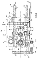
- a mold plate 1 is fixed to a machine stand 8 or
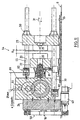
- FIG. 2 shows for the hydraulic components the solution of FIG. 1. However, FIG. 2 has a position measuring system 64 according to FIG equipped with a new solution. Figure 2 shows schematically that also a hydraulic driven machine can be controlled via the travel function.
- Figure 3 shows an example of the new solution.
- the long-stroke support plate 23 can be fixed depending on the selected concept or movably arranged on the machine stand 8, must accordingly the drive carrier plate can be fixed or movable.
- the picture side has a compact structural unit 17 a crank drive 25.
- the assembly 17 consists of a drive carrier plate 24 and a movable platen 22 which is movable on a guide rests on the machine bed 8, and a crank support structure 28 Crank drive 25 is movable on the one hand via a pin 32 Tool clamping plate 22 and on the other hand via a crank or a Eccentric articulated in the crank support structure 28 such that the Crank rod 26 can perform the crank movement according to the eccentricity.
- the eccentricity (e, Figure 11) corresponds to half the lifting height.
- the driven mold half 20 On the opposite side of the movable platen 22 is located the driven mold half 20. With the two mold halves 21 and 20 in closed state of the cavity 35 for the. Deposit the desired one disk-shaped matrices 9, 9 '( Figure 2).
- the CD is not directly in poured the cavity 35.
- a die on one or both sides 9, 9 'inserted, which as a negative mold is the cavity for the flat to be produced Has disk.
- the anchoring and holding force between the two plates is by connecting means, in particular by three or possibly four Pillars 30 ensured.
- Each column 30 is on the die plate on the die side or long-stroke support plate 23 anchored via a nut 38.
- At the Drive carrier plate 24 is attached to a rotatable collar 39, which over a Gear ring 40 engages.
- the fixed nut 38 engages on an internal thread Thread 33 of each column.
- a rotary movement of the ring gear 40 or Pinion 34 is by the rotation of the columns 30 on the nut 38 and that Thread 33 of each column 30 into a linear movement (arrows 29) of the nozzle side Tool mounting plate or long-stroke support plate 23 implemented.
- This movement represents the long or maintenance stroke and is used for quick die change and for the basic setting and cyclical correction of the same.
- the short In contrast, the working stroke is via the crank drive 25 and the movable one Tool platen 22 performed.
- Figure 3 also partially shows schematically the basic concept of the new solution for the production of flat Data carriers such as compact discs. The situation at the transition from the injection phase into the embossing phase.
- FIG. 1 sets Basic diagram with the mechanical engineering core elements of a machine central column nut drive 16.
- K means the spring constant of the column 30, optionally with inclusion of the other deformable components, insofar as the resulting deformation the distance S under a corresponding load influenced between the platen 22 or 23.
- a Drive carrier plate 24 is designated as fixed by PLfix. In this construction concept is the drive carrier plate 24 rigid or fixed to the machine bed 8 or Machine stand connected.
- a crank drive 25 with crank rod 26 as well Crank disk 27 via crank support structure 28 is on the drive carrier plate 24 firmly attached so that the corresponding retention force or the shock-like Forces are directed directly to the machine bed 8.
- the crank drive 25 is designed for the short stroke and serves to apply the embossing force.
- the platen 22 moves himself with the driven mold half 20 for the short stroke, especially for the whole injection molding cycle.
- the direction of movement is indicated by arrow 41 and the path detection by arrow 42.
- the second important function is the mobility of the platen 23 for the Long stroke via the column nut drive 16.
- the platen 23 is for this purpose slidably, depicted on rollers 37 mounted.
- Both movements for the short stroke and the long stroke are preferred over one electric motor drive ensured.
- the concept is that the Drive carrier plate 24 is fixedly connected to the stand 8. Against that are two mold halves 20, 21 relative to one another and to the machine stand 8 slidably mounted.
- the compression function (K x F) becomes at least primary due to the column expansion (K) and the effective compression force (F) determined. All other deformation factors, e.g. of the different plates.
- the Compression force determined in a variety of ways and e.g. in the first approximation the torque of the drive motor 47 are derived.
- the disadvantage is that friction factors, just like acceleration forces, falsify the result.
- the application of the sensors very much advantageous because it is slow, almost static conditions.
- a accurate registration is much easier than during a highly dynamic one Process like the embossing process.
- the electromotive drive is particularly preferably via a servo motor and the mechanical overdrive via a crank drive 95 or an eccentric 61 the path function can be derived from the crank or eccentric position ( ⁇ ) and determined according to the position detection from the control of the servo motor become. Because the end of the movement is defined by the basic setting, they are real conditions in the cavities of the molds from the path function of the movable platen 22 [f ( ⁇ )] and the compression function (K x F) defined with the highest accuracy.
- the drive means are preferred over several embossing sub-steps according to a predetermined or optimizable Speed program controlled.
- the crank or eccentric drive not only has the enormous advantage that the movement function from the Conversion of a circular movement into a linear movement geometrically with the highest Accuracy can be calculated and without additional sensors from the position of the Rotor can be derived in the servo motor.
- the effective compression factor including the Temperature parameters is taken into account in the control and regulation process. This allows the entire embossing process based on the path function via predefined programs of the electromechanical drive according to the task. The beginning and end of the program sequence are already in the basic setting as well with the corresponding setting corrections (force sensor 65) of the machine. For this reason, none are used for production operations within the stamping cycle additional sensors required.
- the new solution allows the most important Sub-parameters that have an influence on the distance relationships, directly in relevant recipes or program parts. With regard the compression, these are all possible deformations, including the Column expansion.
- the path function leaves the special, concrete drive means include.
- FIG. 4a shows a further, very advantageous design idea for the Improve control accuracy.
- the mechanical game everyone correspondingly effective, mechanically movable parts by a biasing spring 50 canceled. It is important that the biasing spring 50 acts in the same direction like the force build-up for the embossing (arrow 50 ').
- FIG. 4b shows a section through a bearing point of a column axis 56
- a seal 52 or 53 is attached to both outer sides. This allows in Include oil or grease lubrication inside for low-friction storage so that here too the demands of a long life and the increased demands of clean room manufacturing are met.
- the optimal control target for the crank drive is within approximately 180 °, as can be seen from FIG. 5b.
- Three different positions are shown in FIG. 5b: the shape is open at the angle of rotation ⁇ 1; Angle of rotation ⁇ 2 represents the embossing gap and ⁇ 3 the position at the maximum embossing force.
- the crank can be in the dead center position, preferably near the dead center.
- F (FIG. 4a) means the effective force on the deformable parts of the machine, in particular on the columns 30.
- FIG. 6 schematically shows the central column nut drive 16 for the long stroke with an electric motor 43 with drive pinion 46 and the drive for the short stroke via a drive motor 47, a gear 48 and the eccentric 61.
- Die Injection unit with plasticizing cylinder is the die mounting plate on the nozzle side 23, and both electromotive drives are the other, fixed carrier plate 24 assigned.
- the maintenance stroke is carried out with a known "mold height adjustment" by means of wheel rim 40 and gear wheels 34 on the column nuts 38 hazards.
- the rotation of the columns 30 can be done with a toothed belt , will be realized.
- box C is with R1, R2, R3, etc., indicated that any computing power installed directly on site and appropriate coordination can be carried out directly. Analogous the control connections St1, St2, St3 can be provided and a corresponding one Optimization of all control and regulation processes can be ensured.
- Figures 7a and 7b schematically show the possibility of complete Speed control / regulation, wherein the figure 7a the closing of the mold and FIG. 7b shows the embossing.
- the term control corresponds to that English expression control, which includes the first two.
- SpO, SP1, SP2, etc. are different pre-selectable embossing columns.
- FIGS. 9 to 11 is a view of FIG the side or from above and a section of the form fit 54.
- a drive carrier plate 24 On The left side of the picture is a drive carrier plate 24, on the right one Module 51 for the work or short stroke directly connected by screws 66 is.
- a die mounting plate 23 On the right half of the picture is a die mounting plate 23 arranged.
- the die-side tool platen 23 is over four on the one hand Columns 30 held opposite the drive carrier plate 24 and down on one Guided tour 55.
- Each of the four columns 30 is in the via a column nut 38
- Nozzle-finished tool platen 23 mounted such that a rotational movement the column axis 56 results in a longitudinal displacement of the mold half 21.
- FIG. 10 shows a removal robot 70 with a robot arm 71 Suction holding head 72 and a CD 73 held thereon.
- the removal robot 70 has its own electric motor 74 and is a fixed removal unit 75 connected to the machine bed. Complete coordination of the Sequence of movements between robot arm 71 and short stroke movement (KH) for the Mold opening. The coordination takes place in the millisecond range and is through suitable sensors secured so that under no circumstances a collision of the moving parts occurs.
- KH short stroke movement
- FIG. 11 shows a section VII-VII of FIG. 10.
- the central column nut drive 16 is preferably used as an actuator of the closing force control, together with a force sensor 66 as an actual value transmitter for detecting the Closing force and a control device used.
- the path is recorded by Stroke movements in the servo motor itself.
- the reproducible positions are the Control / regulation or the coordination of the different axes placed.
- the required accuracy after adjusting the maintenance stroke To be able to ensure is by a biasing device 80 in each of the driven columns 30 the mechanical and bearing play required thread canceled.
- the pressure required to cancel the game can be via springs or done pneumatically and causes a preload between the Drive carrier plate 24 and the long stroke carrier plate 23 that the game at the non-positive flank is canceled.
- eccentric 61 is the example Eccentric radius designated 25 mm, which means a total short stroke of 50 mm would allow.
- the ejection device 81 is not discussed in detail. This can e.g. be trained with pneumatic actuation and the solutions of State of the art.
Landscapes
- Engineering & Computer Science (AREA)
- Manufacturing & Machinery (AREA)
- Mechanical Engineering (AREA)
- Injection Moulding Of Plastics Or The Like (AREA)
- Moulds For Moulding Plastics Or The Like (AREA)
- Shaping Of Tube Ends By Bending Or Straightening (AREA)
Claims (21)
- Procédé de commande et réglage du processus de pressage pour la fabrication de pièces de précision, en particulier des supports de données optiques plats, au moyen d'une presse d'injection comprenant deux moitiés de moule, une moitié de moule mobile (20) et une moitié de moule complémentaire (21), la moitié de moule mobile (20) étant entraínée par un système d'entraínement mécanique ou hydraulique de l'outil de pressage et l'entraínement par adhérence entre la moitié de moule mobile (20) et la moitié de moule complémentaire (21) étant réalisé au moment du réglage de base et pendant l'ensemble du cycle d'injection par l'intermédiaire de moyens d'assemblage de la presse d'injection, lesquels sont extensibles en fonction du gradient de la force de pressage et influencent de manière correspondante la dimension de la fente entre la moitié de moule mobile et la moitié de moule complémentaire, caractérisé en ce que le processus de commande et réglage est effectué pendant le processus de pressage, en évitant une mesure continue de la dimension de la fente entre les deux moitiés de moule, à l'appui d'un programme basé sur la fonction de déplacement de la moitié de moule mobile.
- Procédé selon la revendication 1, caractérisé en ce que la fonction de déplacement est prise comme base de la commandé et réglage du profil autant au cours de la première phase de réduction de la fente de pressage ou de répartition de la matière qu'au cours de la deuxième phase de l'augmentation de la force de pressage.
- Procédé selon la revendication 1 ou 2, caractérisé en ce que la diminution de la fente de pressage, de même que l'augmentation de la force de pressage sont régulées en fonction de la vitesse.
- Procédé selon l'une quelconque des revendications 1 à 3, caractérisé en ce que la phase de diminution de la fente de pressage et la phase consécutive de l'augmentation de la force de pressage sont effectuées de manière enchaínée au moyen d'un réglage de la vitesse.
- Procédé selon l'une quelconque des revendications 1 à 4, caractérisé en ce que la fin du pressage est définie par une position prédéfinissable du déplacement du mécanisme d'entraínement de l'outil de pressage ou de la moitié de moule mobile (20), qui correspond à une force de fermeture pré-réglable et une force optimale dans la phase de la fin du pressage.
- Procédé selon la revendication 5, caractérisé en ce que le préréglage de la force de fermeture et la quantité dosée sont choisis de telle sorte que, non seulement dans la phase de pressage, mais aussi dans la phase consécutive de l'application de la pression supplémentaire, toutes les forces sont absorbées par la masse de la pièce moulée par injection et tout contact métallique entre les moitiés de moule (20, 21) est évité.
- Procédé selon l'une quelconque des revendications 1 à 6, caractérisé en ce que le processus d'application de la pression supplémentaire est effectué à l'appui d'un programme de commande et réglage sous forme de commande et réglage du profil de la position ou du déplacement en fonction du temps, de la force en fonction du temps ou du couple de rotation du mécanisme d'entraínement en fonction du temps, de telle sorte que la structure de la surface est obtenue de la meilleure manière possible et que l'application de la pression supplémentaire active pendant la phase de refroidissement est réduite de telle sorte que l'état de tension interne des pièces moulées par injection et, de ce fait, l'indice de réfraction ne sont autant que possible pas influencés négativement.
- Procédé selon l'une quelconque des revendications 1 à 7, caractérisé en ce que le réglage de base de la presse d'injection en fonction de la force de pressage maximum pendant le processus de pressage est défini d'une manière connue en soi à l'appui de la force de fermeture de base, ainsi que de la position optimale de début et de fin du mécanisme d'entraínement de l'outil de pressage sans produit et avec un moule complètement fermé.
- Procédé selon l'une quelconque des revendications 1 à 8, caractérisé en ce que, à chaque cycle de fabrication, la valeur maximale de la force de pressage réelle générée est enregistrée, des variations de longueur correspondantes des moyens d'assemblage, dues aux influences thermiques, sont détectées de préférence par une comparaison entre la valeur moyenne de plusieurs mesures et la force de pressage théorique et ces variations sont compensées par des mesures correctives au niveau d'un réglage par manchon fileté.
- Procédé selon l'une quelconque des revendications 1 à 8/ caractérisé en ce que le mécanisme d'entraínement de l'outil de pressage est actionné par voie électromécanique par l'intermédiaire d'un servomoteur avec une détection de la position basée sur la fonction de déplacement de l'entraínement électromécanique.
- Procédé selon l'une quelconque des revendications 1 à 10, caractérisé en ce que le réglage de base pour une position finale optimale est effectué par voie électromécanique ou électromotrice par l'intermédiaire d'un réglage par manchon fileté.
- Procédé selon l'une quelconque des revendications 1 à 11, caractérisé en ce que le déplacement pour la course longue ou course de contrôle est mesuré de préférence par une détection du déplacement dans un servomoteur, moyennant quoi la position de la phase de fabrication, déterminée dans le réglage de la force de fermeture, peut être à nouveau approchée avec précision dans un cycle suivant une course de contrôle et, en tant que position reproductible, est prise comme base du processus de commande et réglage ou de la coordination entre les différents arbres de la presse d'injection.
- Dispositif d'entraínement et de commande et réglage pour le côté d'entraínement par conjugaison de forme d'une presse d'injection actionnée par voie électromécanique et/ou hydraulique, comprenant une moitié de moule mobile (20) et une moitié de moule complémentaire (21) avec un processus de pressage pouvant être commandé et réglé pour la fabrication de pièces de précision, en particulier des supports de données plats, l'entraínement par adhérence entre la moitié de moule mobile (20) et la moitié de moule complémentaire (21) pouvant être réalisé par des moyens d'assemblage extensibles de la presse d'injection, l'extensibilité des moyens d'assemblage pouvant influencer la dimension de la fente (S) entre la moitié de moule mobile (20) et la moitié de moule complémentaire (21), caractérisé en ce qu'il est prévu un entraínement de l'outil de pressage, ainsi qu'un dispositif de commande et réglage par programme (49), par lequel le processus de pressage peut être commandé et réglé en évitant une mesure continue de la dimension de la fente (S) entre les deux moitiés de moule (20, 21), à l'appui d'un programme basé sur la fonction de déplacement de la moitié de moule mobile (20).
- Dispositif d'entraínement et de commande et réglage selon la revendication 13, caractérisé en ce que le mécanisme d'entraínement de l'outil de pressage comporte un entraínement avec levier à genouillère, un entraínement à crémaillère, un entraínement à excentrique ou un entraínement à bielle et manivelle (25), lequel est assemblé avec la moitié de moule mobile (20).
- Dispositif d'entraínement et de commande et réglage selon la revendication 14, caractérisé en ce qu'une plaque de support motrice (24) est assemblée fermement avec le socle ou le bâti (8) de la presse d'injection et la moitié de moule mobile (20) est logée de manière mobile par rapport à la plaque de support motrice (24) au moyen du mécanisme d'entraínement de l'outil de pressage, de telle sorte que les forces de réaction issues de l'accélération et du ralentissement des mouvements du moule n'influencent pas négativement la précision de la position de départ du pressage.
- Dispositif d'entraínement et de commande et réglage selon l'une quelconque dès revendications 13 à 15, caractérisé en ce que l'entraínement de l'outil de pressage est conçu sous forme d'entraínement à excentrique ou d'entraínement à bielle et manivelle (25), l'entraínement à excentrique ou l'entraínement à bielle et manivelle (25) étant réalisés de telle sorte que la course de pressage pour la compression maximale est active à proximité du point mort.
- Dispositif d'entraínement et de commande et réglage selon l'une quelconque des revendications 13 à 16, caractérisé en ce que l'entraínement de l'outil de pressage est conçu sous forme de manivelle ou d'excentrique, et la fonction de déplacement est dérivée de la position de la manivelle ou de l'excentrique (ϕ) et peut être calculée en fonction de la détection de la position à l'appui du réglage du servomoteur.
- Dispositif d'entraínement et de commande et réglage selon l'une quelconque des revendications 14 à 17, caractérisé en ce que ledit dispositif comporte un entraínement par manchon fileté (16) et un plateau porte-moule complémentaire, muni de la moitié de moule complémentaire (21), est logé de manière mobile par rapport au bâti (8) de la presse d'injection, le réglage de base de la presse d'injection pouvant être effectué par l'intermédiaire de l'entraínement par manchon fileté (16).
- Dispositif d'entraínement et de commande et réglage selon la revendication 18, caractérisé en ce que l'entraínement centralisé par manchon fileté (16), conjointement avec un capteur de force, conçu sous forme de capteur de valeur réelle destiné à déterminer la force de fermeture, et avec un dispositif de réglage, est conçu pour former un organe de réglage pour le réglage de base de la force de fermeture et le réglage de la force de fermeture.
- Dispositif d'entraínement et de commande et réglage selon l'une quelconque des revendications 13 à 19, caractérisé en ce que le jeu entre les pièces mobiles, en particulier de l'entraínement par manchon fileté (16), est supprimé efficacement par une poussée dans la direction de la force de pressage exercée de préférence par l'intermédiaire de moyens de ressort mécaniques ou pneumatiques.
- Dispositif d'entraínement et de commande et réglage selon l'une quelconque des revendications 14 à 20, caractérisé en ce que ledit dispositif, pour l'entraínement de l'outil de pressage et pour l'entraínement par manchon fileté (16), comporte au moins pour chacun un moteur de commande pouvant être commandé de manière autonome, conçu de préférence sous forme de servomoteur, le dispositif de commande et réglage étant réalisé avec les mémoires nécessaires pour les formules et programmes à sélectionner.
Applications Claiming Priority (5)
| Application Number | Priority Date | Filing Date | Title |
|---|---|---|---|
| PCT/CH2000/000069 WO2000047389A1 (fr) | 1999-02-10 | 2000-02-09 | Unite de fermeture de moule |
| WOPCT/CH00/00069 | 2000-02-09 | ||
| CH253200 | 2000-12-22 | ||
| CH25322000 | 2000-12-22 | ||
| PCT/CH2001/000090 WO2001058662A1 (fr) | 2000-02-09 | 2001-02-09 | Procede de commande/regulation du processus d'estampage ainsi que dispositif d'entrainement et de commande d'outils de moulage par injection |
Publications (2)
| Publication Number | Publication Date |
|---|---|
| EP1254006A1 EP1254006A1 (fr) | 2002-11-06 |
| EP1254006B1 true EP1254006B1 (fr) | 2003-06-25 |
Family
ID=25705666
Family Applications (1)
| Application Number | Title | Priority Date | Filing Date |
|---|---|---|---|
| EP01902230A Expired - Lifetime EP1254006B1 (fr) | 2000-02-09 | 2001-02-09 | Procede de commande/regulation du processus d'estampage ainsi que dispositif d'entrainement et de commande d'outils de moulage par injection |
Country Status (7)
| Country | Link |
|---|---|
| US (1) | US7097791B2 (fr) |
| EP (1) | EP1254006B1 (fr) |
| CN (1) | CN1192870C (fr) |
| AT (1) | ATE243613T1 (fr) |
| AU (1) | AU2001229946A1 (fr) |
| DE (1) | DE50100334D1 (fr) |
| WO (1) | WO2001058662A1 (fr) |
Families Citing this family (21)
| Publication number | Priority date | Publication date | Assignee | Title |
|---|---|---|---|---|
| US6716374B2 (en) | 2000-03-30 | 2004-04-06 | Matsushita Electric Industrial Co., Ltd. | Clamp pressure control method for injection molding process |
| AT413513B (de) * | 2001-12-13 | 2006-03-15 | Engel Austria Gmbh | Zweiplatten-spritzgiessmaschine |
| DE10330658A1 (de) * | 2003-07-08 | 2005-02-17 | Aweba Werkzeugbau Gmbh Aue | Verfahren zur Überwachung und Wartung von Druckgießformen und Druckgießform |
| CN100491107C (zh) * | 2003-10-06 | 2009-05-27 | 住友重机械工业株式会社 | 注塑成型机及注塑成型方法 |
| CN1715033A (zh) * | 2004-06-29 | 2006-01-04 | 柯尼卡美能达精密光学株式会社 | 注射成形用模具和光学元件的成形方法 |
| US20070067049A1 (en) * | 2005-03-21 | 2007-03-22 | The Board Of Regents For Oklahoma State University | Method and apparatus for robust shape filter generation |
| US7875408B2 (en) * | 2007-01-25 | 2011-01-25 | International Business Machines Corporation | Bleachable materials for lithography |
| JP5244823B2 (ja) * | 2007-02-15 | 2013-07-24 | カーハーエス コーポプラスト ゲーエムベーハー | 容器をブロー成形するための方法および装置 |
| EP2357050B1 (fr) * | 2010-02-10 | 2012-10-31 | Loramendi, S.COOP. | Machine pour le moulage des mottes |
| JP5031867B2 (ja) * | 2010-05-18 | 2012-09-26 | 東芝機械株式会社 | 射出成形方法、およびその装置 |
| GB2489754A (en) * | 2011-04-08 | 2012-10-10 | Rpc Containers Ltd | Injection moulding with delayed mould closure |
| CN104802380B (zh) * | 2014-01-24 | 2018-10-26 | 东芝机械株式会社 | 成形机及其驱动方法 |
| JP6400314B2 (ja) * | 2014-03-26 | 2018-10-03 | 住友重機械工業株式会社 | 射出成形機 |
| JP5925926B1 (ja) | 2015-02-19 | 2016-05-25 | 東芝機械株式会社 | 型締装置、成形装置および成形方法 |
| CN105171701A (zh) * | 2015-07-20 | 2015-12-23 | 中国科学院上海光学精密机械研究所 | 高洁净真空位移台 |
| AT518638B1 (de) * | 2016-09-23 | 2017-12-15 | Engel Austria Gmbh | Einspritzeinheit für eine Formgebungsmaschine |
| US10302598B2 (en) | 2016-10-24 | 2019-05-28 | General Electric Company | Corrosion and crack detection for fastener nuts |
| DE102016223980B4 (de) * | 2016-12-01 | 2022-09-22 | Adidas Ag | Verfahren zur Herstellung eines Kunststoffformteils |
| CN108638466B (zh) * | 2018-04-25 | 2020-03-31 | 广州市香港科大霍英东研究院 | 注塑控制系统的开合模控制方法、系统及装置 |
| CN110961966A (zh) * | 2019-12-12 | 2020-04-07 | 广东工业大学 | 一种可调频及往复幅值的往复式进给加工装置 |
| CN116533478A (zh) * | 2023-05-24 | 2023-08-04 | 华南理工大学 | 基于脉宽调制的螺杆振动效果强化系统及方法 |
Family Cites Families (16)
| Publication number | Priority date | Publication date | Assignee | Title |
|---|---|---|---|---|
| FR1539204A (fr) | 1967-08-03 | 1968-09-13 | Plastimonde | Perfectionnements au procédé de moulage des matières plastiques par aménagement du contrôle des opérations de déplacement du moule et du piston d'injection |
| US3736087A (en) * | 1969-12-23 | 1973-05-29 | Netstal Ag | Mold closing unit with separately acting rotary and fluid pressure piston drives |
| AT365119B (de) * | 1979-12-05 | 1981-12-10 | Engel Kg L | Steuerung zum spritzpraegen von insbesondere grossflaechigen und duennwandigen kunststoffteilen |
| CH668740A5 (de) | 1985-11-29 | 1989-01-31 | Netstal Ag Maschf Giesserei | Verfahren und einrichtung zum messen und regeln der schliesskraft einer kunststoff-spritzgiessmaschine. |
| US4828769A (en) | 1986-05-05 | 1989-05-09 | Galic/Maus Ventures | Method for injection molding articles |
| DE3725167C2 (de) | 1986-07-30 | 2000-08-31 | Toshiba Machine Co Ltd | Verfahren zur Steuerung der Formzuhaltung sowie Kompression eines in einem Formraum einer Spritzgießform eingespritzen Kunststoffes einer Spritzgießmaschine sowie Spritzgießmaschine |
| JPS63307921A (ja) * | 1987-06-10 | 1988-12-15 | Fanuc Ltd | 可変ストロ−ク式クランク型締装置 |
| JPH01241420A (ja) * | 1988-03-24 | 1989-09-26 | Komatsu Ltd | 射出圧縮成形機の成形方法およびその成形装置 |
| JPH02106313A (ja) * | 1988-10-14 | 1990-04-18 | Japan Steel Works Ltd:The | 電動式射出成形機の射出圧縮制御方法およびその装置 |
| JP2906349B2 (ja) * | 1989-11-01 | 1999-06-21 | 住友重機械工業株式会社 | 光ディスク基板の製造方法 |
| JP2709755B2 (ja) * | 1991-06-28 | 1998-02-04 | ファナック株式会社 | 電動式射出成形機における位置決め補正方法及び補正装置 |
| JPH07256722A (ja) * | 1994-03-24 | 1995-10-09 | Fanuc Ltd | 射出成形機における射出成形制御方法 |
| EP0674985B1 (fr) * | 1994-04-02 | 1999-08-11 | Karl Hehl | Unité de fermeture de moule pour une machine à mouler par injection et procédé pour son opération |
| EP0775567B1 (fr) * | 1995-06-14 | 2001-08-22 | Fanuc Ltd | Mecanisme de serrage de moule pour machine de moulage par injection |
| US5945047A (en) * | 1997-03-13 | 1999-08-31 | The Japan Steel Works, Ltd. | Method of injection-compression molding |
| BR0008148A (pt) | 1999-02-10 | 2001-11-06 | Netstal Ag Maschf Giesserei | Unidade de fecho de molde |
-
2001
- 2001-02-09 CN CN01804710.6A patent/CN1192870C/zh not_active Expired - Fee Related
- 2001-02-09 WO PCT/CH2001/000090 patent/WO2001058662A1/fr not_active Ceased
- 2001-02-09 DE DE50100334T patent/DE50100334D1/de not_active Expired - Lifetime
- 2001-02-09 EP EP01902230A patent/EP1254006B1/fr not_active Expired - Lifetime
- 2001-02-09 US US10/203,275 patent/US7097791B2/en not_active Expired - Fee Related
- 2001-02-09 AU AU2001229946A patent/AU2001229946A1/en not_active Abandoned
- 2001-02-09 AT AT01902230T patent/ATE243613T1/de not_active IP Right Cessation
Also Published As
| Publication number | Publication date |
|---|---|
| CN1398218A (zh) | 2003-02-19 |
| DE50100334D1 (de) | 2003-07-31 |
| US20030047827A1 (en) | 2003-03-13 |
| CN1192870C (zh) | 2005-03-16 |
| US7097791B2 (en) | 2006-08-29 |
| EP1254006A1 (fr) | 2002-11-06 |
| AU2001229946A1 (en) | 2001-08-20 |
| WO2001058662A1 (fr) | 2001-08-16 |
| ATE243613T1 (de) | 2003-07-15 |
Similar Documents
| Publication | Publication Date | Title |
|---|---|---|
| EP1254006B1 (fr) | Procede de commande/regulation du processus d'estampage ainsi que dispositif d'entrainement et de commande d'outils de moulage par injection | |
| DE69808187T2 (de) | Elektrisch betätigte Spritzgiessmaschine und Spritzgiessverfahren unter Verwendung der geeigneten Maschine | |
| DE69511558T2 (de) | Linsendickeneinstellmöglichkeit in kunststoffspritzgiessform | |
| EP1150821B1 (fr) | Unite de fermeture de moule | |
| DE69410392T2 (de) | Mechanische Presse mit einer Vorrichtung zum Nachstellen der Lage des unteren Totpunktes | |
| DE102013017358B4 (de) | SPRITZGIEßMASCHINE MIT FUNKTION ZUM EINSTELLEN DES GLEICHGEWICHTS DER VERBINDUNGSSTANGEN | |
| EP2583811B2 (fr) | Procédé de quantification de basculements de procédés dans le cadre d'un processus d'injection d'une machine de moulage par injection | |
| DE69608324T2 (de) | Spritzgiessmaschine mit offenem Zugriff zum Formbereich | |
| EP0674985B1 (fr) | Unité de fermeture de moule pour une machine à mouler par injection et procédé pour son opération | |
| DE102015114845B4 (de) | Verfahren und Gerät zum Spritzgießen von Kunststoffmaterialien | |
| EP0837764B1 (fr) | Procede pour la regulation ou la commande d'une presse d'injection | |
| EP1343621B1 (fr) | Procede et dispositif pour le moulage par injection de supports de donnees optiques plats ayant un poids precis | |
| DE68902731T2 (de) | Verfahren zum einpressen eines inerten gases in einen geschmolzenen kunststoff in einer form einer spritzgiessmaschine und vorrichtung hierfuer. | |
| DE69918402T2 (de) | Verfahren zur Regelung der Spritzphase bei einer Spritzgiessmaschine | |
| DE2906858A1 (de) | Pressgussvorrichtung | |
| EP0461143B1 (fr) | Procede pour reguler la phase de maintien en pression lors de l'injection de thermoplastiques | |
| DE69028634T2 (de) | Formschliesssystem | |
| EP1420930B1 (fr) | Procede et dispositif de production automatique de plaques minces | |
| DE102006020213A1 (de) | Presse zur Herstellung von Preßlingen aus Pulvermaterial | |
| EP1423248A1 (fr) | Procede et dispositif pour produire des pieces moulees planes en matiere plastique, notamment des disques en matiere plastique | |
| EP0814924B1 (fr) | Procede pour assurer la qualite de moules en sable par mesure du flux d'huile envoye a la partie superieure d'une presse | |
| EP1280647B1 (fr) | Machine de moulage par injection a entrainement excentrique | |
| DE19529279C1 (de) | Druckgießmaschine | |
| DE3816147C1 (en) | Device for manufacturing glass articles according to the pressing method | |
| WO2004016411A1 (fr) | Dispositif de compensation des forces de basculement se produisant lors du moulage par injection-compression et procede de production de pieces moulees en plastique |
Legal Events
| Date | Code | Title | Description |
|---|---|---|---|
| PUAI | Public reference made under article 153(3) epc to a published international application that has entered the european phase |
Free format text: ORIGINAL CODE: 0009012 |
|
| 17P | Request for examination filed |
Effective date: 20020515 |
|
| AK | Designated contracting states |
Kind code of ref document: A1 Designated state(s): AT BE CH CY DE DK ES FI FR GB GR IE IT LI LU MC NL PT SE TR |
|
| AX | Request for extension of the european patent |
Free format text: AL;LT;LV;MK;RO;SI |
|
| GRAH | Despatch of communication of intention to grant a patent |
Free format text: ORIGINAL CODE: EPIDOS IGRA |
|
| GRAH | Despatch of communication of intention to grant a patent |
Free format text: ORIGINAL CODE: EPIDOS IGRA |
|
| GRAA | (expected) grant |
Free format text: ORIGINAL CODE: 0009210 |
|
| AK | Designated contracting states |
Designated state(s): AT BE CH CY DE DK ES FI FR GB GR IE IT LI LU MC NL PT SE TR |
|
| PG25 | Lapsed in a contracting state [announced via postgrant information from national office to epo] |
Ref country code: IT Free format text: LAPSE BECAUSE OF FAILURE TO SUBMIT A TRANSLATION OF THE DESCRIPTION OR TO PAY THE FEE WITHIN THE PRESCRIBED TIME-LIMIT;WARNING: LAPSES OF ITALIAN PATENTS WITH EFFECTIVE DATE BEFORE 2007 MAY HAVE OCCURRED AT ANY TIME BEFORE 2007. THE CORRECT EFFECTIVE DATE MAY BE DIFFERENT FROM THE ONE RECORDED. Effective date: 20030625 Ref country code: NL Free format text: LAPSE BECAUSE OF FAILURE TO SUBMIT A TRANSLATION OF THE DESCRIPTION OR TO PAY THE FEE WITHIN THE PRESCRIBED TIME-LIMIT Effective date: 20030625 Ref country code: GB Free format text: LAPSE BECAUSE OF FAILURE TO SUBMIT A TRANSLATION OF THE DESCRIPTION OR TO PAY THE FEE WITHIN THE PRESCRIBED TIME-LIMIT Effective date: 20030625 Ref country code: FI Free format text: LAPSE BECAUSE OF FAILURE TO SUBMIT A TRANSLATION OF THE DESCRIPTION OR TO PAY THE FEE WITHIN THE PRESCRIBED TIME-LIMIT Effective date: 20030625 Ref country code: FR Free format text: LAPSE BECAUSE OF FAILURE TO SUBMIT A TRANSLATION OF THE DESCRIPTION OR TO PAY THE FEE WITHIN THE PRESCRIBED TIME-LIMIT Effective date: 20030625 Ref country code: CY Free format text: LAPSE BECAUSE OF FAILURE TO SUBMIT A TRANSLATION OF THE DESCRIPTION OR TO PAY THE FEE WITHIN THE PRESCRIBED TIME-LIMIT Effective date: 20030625 Ref country code: TR Free format text: LAPSE BECAUSE OF FAILURE TO SUBMIT A TRANSLATION OF THE DESCRIPTION OR TO PAY THE FEE WITHIN THE PRESCRIBED TIME-LIMIT Effective date: 20030625 Ref country code: IE Free format text: LAPSE BECAUSE OF FAILURE TO SUBMIT A TRANSLATION OF THE DESCRIPTION OR TO PAY THE FEE WITHIN THE PRESCRIBED TIME-LIMIT Effective date: 20030625 |
|
| REG | Reference to a national code |
Ref country code: GB Ref legal event code: FG4D Free format text: NOT ENGLISH |
|
| REG | Reference to a national code |
Ref country code: CH Ref legal event code: EP |
|
| REG | Reference to a national code |
Ref country code: IE Ref legal event code: FG4D Free format text: GERMAN |
|
| REF | Corresponds to: |
Ref document number: 50100334 Country of ref document: DE Date of ref document: 20030731 Kind code of ref document: P |
|
| REG | Reference to a national code |
Ref country code: CH Ref legal event code: NV Representative=s name: PATENTANWALT ERNST ACKERMANN |
|
| PG25 | Lapsed in a contracting state [announced via postgrant information from national office to epo] |
Ref country code: PT Free format text: LAPSE BECAUSE OF FAILURE TO SUBMIT A TRANSLATION OF THE DESCRIPTION OR TO PAY THE FEE WITHIN THE PRESCRIBED TIME-LIMIT Effective date: 20030925 Ref country code: DK Free format text: LAPSE BECAUSE OF FAILURE TO SUBMIT A TRANSLATION OF THE DESCRIPTION OR TO PAY THE FEE WITHIN THE PRESCRIBED TIME-LIMIT Effective date: 20030925 Ref country code: SE Free format text: LAPSE BECAUSE OF FAILURE TO SUBMIT A TRANSLATION OF THE DESCRIPTION OR TO PAY THE FEE WITHIN THE PRESCRIBED TIME-LIMIT Effective date: 20030925 Ref country code: GR Free format text: LAPSE BECAUSE OF FAILURE TO SUBMIT A TRANSLATION OF THE DESCRIPTION OR TO PAY THE FEE WITHIN THE PRESCRIBED TIME-LIMIT Effective date: 20030925 |
|
| LTIE | Lt: invalidation of european patent or patent extension |
Effective date: 20030625 |
|
| NLV1 | Nl: lapsed or annulled due to failure to fulfill the requirements of art. 29p and 29m of the patents act | ||
| PG25 | Lapsed in a contracting state [announced via postgrant information from national office to epo] |
Ref country code: ES Free format text: LAPSE BECAUSE OF FAILURE TO SUBMIT A TRANSLATION OF THE DESCRIPTION OR TO PAY THE FEE WITHIN THE PRESCRIBED TIME-LIMIT Effective date: 20031222 |
|
| GBV | Gb: ep patent (uk) treated as always having been void in accordance with gb section 77(7)/1977 [no translation filed] |
Effective date: 20030625 |
|
| PG25 | Lapsed in a contracting state [announced via postgrant information from national office to epo] |
Ref country code: LU Free format text: LAPSE BECAUSE OF NON-PAYMENT OF DUE FEES Effective date: 20040209 |
|
| REG | Reference to a national code |
Ref country code: IE Ref legal event code: FD4D |
|
| PG25 | Lapsed in a contracting state [announced via postgrant information from national office to epo] |
Ref country code: BE Free format text: LAPSE BECAUSE OF NON-PAYMENT OF DUE FEES Effective date: 20040228 Ref country code: MC Free format text: LAPSE BECAUSE OF NON-PAYMENT OF DUE FEES Effective date: 20040228 |
|
| PLBE | No opposition filed within time limit |
Free format text: ORIGINAL CODE: 0009261 |
|
| STAA | Information on the status of an ep patent application or granted ep patent |
Free format text: STATUS: NO OPPOSITION FILED WITHIN TIME LIMIT |
|
| 26N | No opposition filed |
Effective date: 20040326 |
|
| EN | Fr: translation not filed | ||
| BERE | Be: lapsed |
Owner name: *NETSTAL-MASCHINEN A.G. Effective date: 20040228 |
|
| PGFP | Annual fee paid to national office [announced via postgrant information from national office to epo] |
Ref country code: AT Payment date: 20070206 Year of fee payment: 7 |
|
| PGFP | Annual fee paid to national office [announced via postgrant information from national office to epo] |
Ref country code: CH Payment date: 20070227 Year of fee payment: 7 |
|
| REG | Reference to a national code |
Ref country code: CH Ref legal event code: PL |
|
| PG25 | Lapsed in a contracting state [announced via postgrant information from national office to epo] |
Ref country code: CH Free format text: LAPSE BECAUSE OF NON-PAYMENT OF DUE FEES Effective date: 20080229 Ref country code: LI Free format text: LAPSE BECAUSE OF NON-PAYMENT OF DUE FEES Effective date: 20080229 |
|
| PG25 | Lapsed in a contracting state [announced via postgrant information from national office to epo] |
Ref country code: AT Free format text: LAPSE BECAUSE OF NON-PAYMENT OF DUE FEES Effective date: 20080209 |
|
| PGFP | Annual fee paid to national office [announced via postgrant information from national office to epo] |
Ref country code: DE Payment date: 20100219 Year of fee payment: 10 |
|
| REG | Reference to a national code |
Ref country code: DE Ref legal event code: R119 Ref document number: 50100334 Country of ref document: DE Effective date: 20110901 |
|
| PG25 | Lapsed in a contracting state [announced via postgrant information from national office to epo] |
Ref country code: DE Free format text: LAPSE BECAUSE OF NON-PAYMENT OF DUE FEES Effective date: 20110901 |