EP1254691A1 - Filtre à air - Google Patents
Filtre à air Download PDFInfo
- Publication number
- EP1254691A1 EP1254691A1 EP02252990A EP02252990A EP1254691A1 EP 1254691 A1 EP1254691 A1 EP 1254691A1 EP 02252990 A EP02252990 A EP 02252990A EP 02252990 A EP02252990 A EP 02252990A EP 1254691 A1 EP1254691 A1 EP 1254691A1
- Authority
- EP
- European Patent Office
- Prior art keywords
- filter
- air
- envelopes
- filtering
- extraction apparatus
- Prior art date
- Legal status (The legal status is an assumption and is not a legal conclusion. Google has not performed a legal analysis and makes no representation as to the accuracy of the status listed.)
- Granted
Links
- 238000001914 filtration Methods 0.000 claims abstract description 48
- 238000000605 extraction Methods 0.000 claims abstract description 21
- 239000000356 contaminant Substances 0.000 claims abstract description 9
- 239000011148 porous material Substances 0.000 claims abstract description 7
- 230000001419 dependent effect Effects 0.000 claims abstract description 4
- 238000011045 prefiltration Methods 0.000 claims description 47
- 239000000463 material Substances 0.000 claims description 29
- 238000000034 method Methods 0.000 claims description 11
- 238000004519 manufacturing process Methods 0.000 claims description 8
- 239000002245 particle Substances 0.000 claims description 7
- 238000005476 soldering Methods 0.000 claims description 5
- 229920003023 plastic Polymers 0.000 claims description 3
- 239000004033 plastic Substances 0.000 claims description 3
- 238000000746 purification Methods 0.000 description 19
- 238000009958 sewing Methods 0.000 description 7
- 238000000429 assembly Methods 0.000 description 5
- 239000003517 fume Substances 0.000 description 4
- 230000000712 assembly Effects 0.000 description 3
- 239000000428 dust Substances 0.000 description 3
- 239000013618 particulate matter Substances 0.000 description 3
- 239000004800 polyvinyl chloride Substances 0.000 description 3
- 229920000915 polyvinyl chloride Polymers 0.000 description 3
- 229910001220 stainless steel Inorganic materials 0.000 description 3
- 239000010935 stainless steel Substances 0.000 description 3
- XECAHXYUAAWDEL-UHFFFAOYSA-N acrylonitrile butadiene styrene Chemical compound C=CC=C.C=CC#N.C=CC1=CC=CC=C1 XECAHXYUAAWDEL-UHFFFAOYSA-N 0.000 description 2
- 229920000122 acrylonitrile butadiene styrene Polymers 0.000 description 2
- 239000004676 acrylonitrile butadiene styrene Substances 0.000 description 2
- 238000004887 air purification Methods 0.000 description 2
- 238000010276 construction Methods 0.000 description 2
- 238000010586 diagram Methods 0.000 description 2
- 239000007789 gas Substances 0.000 description 2
- 231100001261 hazardous Toxicity 0.000 description 2
- 239000004831 Hot glue Substances 0.000 description 1
- FAPWRFPIFSIZLT-UHFFFAOYSA-M Sodium chloride Chemical compound [Na+].[Cl-] FAPWRFPIFSIZLT-UHFFFAOYSA-M 0.000 description 1
- 239000000853 adhesive Substances 0.000 description 1
- 230000001070 adhesive effect Effects 0.000 description 1
- 230000001413 cellular effect Effects 0.000 description 1
- 239000004568 cement Substances 0.000 description 1
- 238000004891 communication Methods 0.000 description 1
- 238000011109 contamination Methods 0.000 description 1
- 238000005520 cutting process Methods 0.000 description 1
- 230000000694 effects Effects 0.000 description 1
- 238000005530 etching Methods 0.000 description 1
- 238000003698 laser cutting Methods 0.000 description 1
- 239000002184 metal Substances 0.000 description 1
- 229910052751 metal Inorganic materials 0.000 description 1
- 238000004021 metal welding Methods 0.000 description 1
- 150000002739 metals Chemical class 0.000 description 1
- 238000012544 monitoring process Methods 0.000 description 1
- 238000004806 packaging method and process Methods 0.000 description 1
- 238000004023 plastic welding Methods 0.000 description 1
- 229920000728 polyester Polymers 0.000 description 1
- 239000000843 powder Substances 0.000 description 1
- 239000013464 silicone adhesive Substances 0.000 description 1
- 239000002904 solvent Substances 0.000 description 1
- 239000000126 substance Substances 0.000 description 1
- 238000011282 treatment Methods 0.000 description 1
- 238000003466 welding Methods 0.000 description 1
Images




Classifications
-
- B—PERFORMING OPERATIONS; TRANSPORTING
- B01—PHYSICAL OR CHEMICAL PROCESSES OR APPARATUS IN GENERAL
- B01D—SEPARATION
- B01D46/00—Filters or filtering processes specially modified for separating dispersed particles from gases or vapours
- B01D46/0084—Filters or filtering processes specially modified for separating dispersed particles from gases or vapours provided with safety means
- B01D46/0086—Filter condition indicators
-
- A—HUMAN NECESSITIES
- A47—FURNITURE; DOMESTIC ARTICLES OR APPLIANCES; COFFEE MILLS; SPICE MILLS; SUCTION CLEANERS IN GENERAL
- A47L—DOMESTIC WASHING OR CLEANING; SUCTION CLEANERS IN GENERAL
- A47L9/00—Details or accessories of suction cleaners, e.g. mechanical means for controlling the suction or for effecting pulsating action; Storing devices specially adapted to suction cleaners or parts thereof; Carrying-vehicles specially adapted for suction cleaners
- A47L9/10—Filters; Dust separators; Dust removal; Automatic exchange of filters
- A47L9/14—Bags or the like; Rigid filtering receptacles; Attachment of, or closures for, bags or receptacles
-
- B—PERFORMING OPERATIONS; TRANSPORTING
- B01—PHYSICAL OR CHEMICAL PROCESSES OR APPARATUS IN GENERAL
- B01D—SEPARATION
- B01D46/00—Filters or filtering processes specially modified for separating dispersed particles from gases or vapours
- B01D46/0001—Making filtering elements
-
- B—PERFORMING OPERATIONS; TRANSPORTING
- B01—PHYSICAL OR CHEMICAL PROCESSES OR APPARATUS IN GENERAL
- B01D—SEPARATION
- B01D46/00—Filters or filtering processes specially modified for separating dispersed particles from gases or vapours
- B01D46/02—Particle separators, e.g. dust precipitators, having hollow filters made of flexible material
-
- B—PERFORMING OPERATIONS; TRANSPORTING
- B01—PHYSICAL OR CHEMICAL PROCESSES OR APPARATUS IN GENERAL
- B01D—SEPARATION
- B01D46/00—Filters or filtering processes specially modified for separating dispersed particles from gases or vapours
- B01D46/56—Filters or filtering processes specially modified for separating dispersed particles from gases or vapours with multiple filtering elements, characterised by their mutual disposition
- B01D46/58—Filters or filtering processes specially modified for separating dispersed particles from gases or vapours with multiple filtering elements, characterised by their mutual disposition connected in parallel
Definitions
- the present invention relates to a filter for air extraction apparatus, air extraction apparatus and a method of manufacturing a filter for air extraction apparatus.
- Extraction systems for extracting and filtering air to remove air-entrained particulate matter and gases are known. Apparatus of this type is used in a wide variety of industrial situations such as, for example, in the electronics industry and in the pharmaceutical industry. Workstations on an assembly at which fume and/or dust generating operations are carried such as for example, the fabrication of electronic circuit boards, requires an extraction system. Fume extraction assemblies manufactured and sold by the present applicant under the trademark "Purex" include a number of articulating arm assemblies for different workstations, linked together by appropriate pipework to a pump and filter assembly.
- air extraction apparatus comprising: a support structure for supporting a filter during filtering; and a filter configured to be located within said support structure, said filter being assembled from a porous material arranged to collect contaminants, and comprising a bag with a constricted inlet for receiving contaminated air, characterised in that: said bag is formed from a plurality of envelopes having filtering side walls and each of said envelopes has at least one orifice connected to an orifice of an adjacent envelope; and said support structure is configured such that during filtering the area of contact between adjacent envelopes is dependent upon the number of envelopes included in the filter.
- the filter comprises a plurality of connected envelopes, it provides an increased surface filtering area when compared to filter-bags having a single compartment. Furthermore, since the area of contact between adjacent envelopes is dependent upon the number of envelopes included in the filter, the support structure may be a simple structure which allows easy replacement of the filter.
- each said envelope comprises a first and second sheet of filtering material and the outer perimeter of said first sheet is connected to the outer perimeter of said second sheet.
- said sheets of filtering material are connected by stitching.
- the number of envelopes included in said filter and the dimensions of the support structure are such that during filtering the side walls of the envelopes contact with adjacent filtering side walls only in the vicinity of said orifices.
- substantially all of the filtering material of the filter is used during filtering, since the area of contact between adjacent filtering side walls is limited to the vicinity of the orifices.
- said number of envelopes is such that the filtering surface area of said filter is maximised.
- said envelope defines a compartment such that said connected orifices provide connection between said compartments, and said filter is configured such that in use a portion of air drawn into said inlet passes through all of said compartments.
- said filter comprises a material having a graded structure, such that it has a more open structure on the inside of the filter than on the outside.
- said filter is configured as a pre-filter and said apparatus includes a further filter configured to filter air received from said pre-filter.
- said support structure consists of perforated panels.
- said apparatus comprises walls defining a chamber and said support structure consists of perforated panels attached to said walls thereby defining passageways for air flow between said walls and said perforated panels.
- said apparatus is arranged to filter air extracted from electronic circuitry soldering apparatus.
- said apparatus is arranged to filter air which is contaminated with particles of plastics material.
- a method of manufacturing a filter for air extraction apparatus comprising a bag with a restricted inlet for receiving contaminated air, wherein said method comprises the steps of: (a) providing a plurality of sheets of a porous material arranged to collect contaminants; (b) defining an orifice in selected ones of said sheets; and (c) connecting pairs of said selected sheets around their orifices to form subassemblies; and (d) connecting said subassemblies together to form a plurality of envelopes having filtering side walls such that each of said envelopes has at least one orifice connected to an orifice of an adjacent envelope.
- each of said envelopes comprises a first and second sheet of filtering material and the outer perimeter of said first sheet is connected to the outer perimeter of said second sheet.
- said sheets of filtering material are connected by a sewing process.
- said filter is configured to be located within a support means of an air extraction apparatus and said filter is formed from a particular number of envelopes such that during operation an adjacent pair of connected filtering side walls are in mutual contact only in the vicinity of connection.
- said particular number is such that the filtering surface of said filter is maximised.
- said filter is configured such that each of said envelopes defines a compartment such that said connected orifices provide connection between said compartments, and said filter is configured such that in use a portion of air drawn into said inlet passes through all of said compartments.
- said sheets comprise a material having a graded structure, such that it has a more open structure on the inside of the filter than on the outside.
- the restricted inlet is defined by a connection means for connecting to an air inlet of said extraction apparatus, and said method includes the steps of: connecting one of said selected sheets to said connection means to form an inlet subassembly; and connecting said inlet subassembly to a one of said subassemblies to form an envelope of said filter.
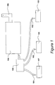
- FIG. 1 An air purification system is illustrated in Figure 1 in which purification arms 101, 102, 103 are connected to a centralised purification system 104 via a conduit 105.
- the conduit 105 allows up to fifty purification arms to be connected.
- filter life can be enhanced by installing a multiple of cellular systems or, with fewer systems connected, higher velocity of purification may be performed.
- the purification system 104 provides sufficient purification for filtered air to be vented to atmosphere via an exhaust vent 106.
- Purification arms 101, 102 and 103 can be arranged to remove and purify hazardous fumes and dust from many processors 107,108 and 109 that create contaminants of this type, including chemical and biological treatments, manual and automated soldering, etching, marking and cutting metals and plastics, welding, laser processes and powder handling and packaging etc.
- Purification system 104 is shown in Figure 2 and comprises, in its base configuration, a stainless steel cabinet of a size substantially similar to that of the domestic fridge freezer. Contaminated air is received at an air inlet 201 and purified air is supplied to an air outlet (shown in Figure 3).
- An LCD display 203 indicates operating conditions, such as filterable filter capacity, gas sensing, particle sensing, days to next service and temperature warning indicator.
- the front panel also includes control buttons, including on and off switches.
- An upper door 204 provides access to a main filter, while a lower door 205 provides access to a pre-filter, for the purposes of filter replacement.
- Air inlet 201 supplies contaminated air to a pre-filter 301, that in turn supplies partially filtered air to a main filter 302 that in turn supplies relatively well filtered air to an exhaust filter 303.
- the output from the exhaust filter 303 is then supplied to the exhaust outlet 306 via a continuous exhaust air monitoring unit 304 that sounds an audible alarm 305 if air quality drops between a predetermined level.
- the combination of the pre-filter 301, main filter 302 and exhaust filter 303 facilitates careful matching to provide an optimum combination for the particular type of hazardous fumes and dust that are being removed from a contaminated air stream.
- the purification system 104 is shown in Figure 4 with the lower door 205 open allowing the pre-filter 401 to be accessed.
- the pre-filter 401 is located in a chamber 402 having an outlet (not shown) through which air is drawn from the chamber during operation.
- the air drawn from the chamber is subsequently drawn through the main filter 302.
- Each of the six walls of chamber 402 has a perforated stainless steel panel fixed parallel to it, thereby defining six corresponding passageways through which air may flow.
- the floor of the chamber has a perforated panel 403
- the left side wall has a perforated panel 404
- the inside of the door 205 has a perforated panel 405.
- the perforated panels are stainless steel sheets having an array of apertures.
- the perforated panels are fabricated from a mesh material.
- the perforated panels provide a support structure which maintains the location of the pre-filter while allowing air to be drawn from all around it.
- the air inlet 201 comprises a pipe section fixed rigidly in the side wall of the chamber 402, such that it allows air to enter the chamber.
- the pre-filter 401 comprises a bag formed from a porous material arranged to collect airborne contaminants.
- the pre-filter has a constricted inlet comprising a pipe (detailed later in Figure 8 and 9 ) which is configured to be a good push fit within inlet pipe section 201. Therefore, during operation of the purification system 104, contaminated air enters the pre-filter from the air inlet 201, and some of the larger particulate matter is collected by the filter while the pre-filtered air passes through the porous walls of the pre-filter and eventually escapes through the chamber's outlet.
- the pre-filter fills with particulate matter, its porosity gradually reduces, and eventually the pre-filter must be replaced.
- the pipe which forms its inlet is pulled and twisted from the inlet pipe 201, and then the pre-filter is withdrawn from the chamber 402 and disposed of.
- a new pre-filter is then located in its operating position by the reverse procedure. Since the pre-filter is bag-like and has a restricted inlet, an operator replacing the filter is not exposed to its inner contaminated surface, and the contaminants contained within the used pre-filter are substantially maintained within it during the replacement process. Thus risks of contaminating the operator replacing the filter are reduced compared to other known filters which have an open configuration, such that the contaminated side of the filtering material is exposed to the operator.
- the particles tend to enter the pre-filter 401 and fall towards the bottom of the bag, thus leaving the pores within the upper regions of the walls relatively free from contamination.
- the system 104 is used to purify air extracted from certain other processes such as laser cutting or welding of plastics, or soldering of electronic circuitry by a wave soldering process or in a re-flow oven process, the contaminant entrapped by the pre-filter tends to stick to all of its inner surfaces. Therefore, in such circumstances, the useful life of the pre-filter is proportional to its filtering surface area.
- the pre-filter 401 has a long useful life when compared to known bag-like pre-filters of comparable volume, since filter 401 has been configured to have a relatively large filtering surface area.
- known filter bags comprise substantially of one cube or cuboid compartment
- the filter of the present application has a plurality of interconnected compartments defined by a series of envelopes such as envelopes 406 and 407. Therefore, it is this structure of connected envelopes which provides the filter 401 with its large filtering area and subsequent long life.
- FIG. 5 A schematic cross-sectional diagram of the pre-filter 401 located within the chamber 402 is shown in Figure 5. As described above, the pre-filter 401 is supported by panels such as panels 403 and 404, that are perforated to allow air to be drawn out from all around the pre-filter and out through chamber outlet 501.
- the air inlet pipe 201 of the purification system is fixed to the wall of the chamber by a screw threaded mechanism 502.
- the pre-filter 401 includes an inlet pipe 503 which is a good push fit in pipe 201.
- the filter 401 comprises a bag having a total of nine envelopes 406, 407, 504, 505, 506, 507, 508, 509 and 510 which each define one of the nine compartments 511 to 519 within the bag.
- Each of the envelopes 407 and 504 to 509 has an orifice within each of its two side walls of filtering material, to provide connection between its compartment and adjacent compartments on either side.
- Envelope 510 has an orifice 520 in just one of its sides walls, 539, to allow communication between its compartment 519 and the compartment 518 of its only neighbouring envelope 509.
- Envelope 406 has an orifice in each of its two side walls, 531 and 541: the first orifice 521 being connected to the orifice of its adjacent envelope 407, and the second orifice 522 being connected to a tube 523 of filtering material which is itself bonded to the inlet pipe 503.
- the pre-filter has a series of connecting compartments, connected such that during use air entering the inlet pipe 503 of the pre-filter enters the first compartment 511 and a portion of that air passes through each of the compartments in the series before passing into the end compartment 519 and out through its side walls.
- the filter 401 has a total of 18 side walls, each of which has an area almost as large as the side walls of the chamber itself.
- the filtering surface of the filter 401 is therefore much larger than a cuboid shaped filter bag as previously known.
- each envelope's side walls tend to balloon out towards a side wall of an adjacent envelope.
- side wall 541 of envelope 406 tends to be brought closer to side wall 532 of envelope 407. If too many envelopes are included in the construction of a filter, for use in a particular support structure, the side walls come into contact over a proportion of their area and that proportion is lost for filtering purposes.
- the number of envelopes be such that during use the envelope side walls do not press against one another, i.e. the filtering side walls are only in contact with adjacent side walls in the vicinity of the connection between them. In this manner, substantially all of the surface area of each envelope is used for filtering.
- the pre-filter 401 is located in a support structure having an internal height of 360mm , a depth (from front to back) of 360mm and a width 360mm. Consequently, the pre-filter has envelopes having a length of 360mm and width 360mm to fit the support structure and it has nine envelopes, since this is the most envelopes which can fit across the width of the support structure without losing significant filtering surface due to the above described contacting of side walls. Thus pre-filter 401 has a number of envelopes which maximises the filtering area, given the dimensions of the support structure.
- the optimum number of envelopes also depends on the material from which the filter is constructed.
- the material used is relatively thick, but in an alternative embodiment, the pre-filter material is a filtering paper and consequently the optimum number of envelopes is increased.
- the orifices connecting compartments of the filter 401 are located centrally in their respective side walls, and thus the orifices of all the envelopes fall along a straight horizontal line when the filter is located in the chamber 402.
- the orifices are all arranged equally off centre.
- the orifices are arranged such that air enters an envelope towards its upper end and exits towards its lower end, or enters at its lower end and exits towards its upper end.
- the first steps in manufacturing the pre-filter 401 are illustrated in Figure 6.
- a sheet of material 601 is cut to a rectangular shape, (which in the present example is a 36 centimetre square), and a 7 centimetre circular orifice 611 is cut from its centre.
- a second sheet of material 602 having a orifice 612 is then cut to replicate sheet 601.
- Each of the sheets 601 and 602 is a made from 20mm thick, EU grade 5 filter material.
- the filter material is non-woven polyester material, and it has a graded structure. That is, it presents a more open structure for use on the inside of the filter than on the outside. Therefore, during use, particles of varying sizes are entrapped at various levels throughout the thickness of the material, with larger particles being caught, on average, earlier than smaller particles. Thus the graded structure in effect provides for a larger filter capacity.
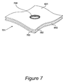
- the sheets 601 and 602 of Figure 6 are shown sewn together in Figure 7. Having cut out the two sheets 601 and 602, the two sheets are sewn together by stitching 704 around the perimeter of their orifices, such that the two rectangular shapes are aligned, to form sub-assembly 701.
- the contacting inner surfaces 702 and 703 of sub-assembly 701 represent a portion of the outer surface of the complete filter 401.
- Sub-assembly 701 is replicated to produce sub-assemblies 802, 803, 804, 805, 806, 807 and 808.
- Sub-assembly 701 is then attached to subassembly 802 by sewing together the outer perimeter of sheet 602 and outer perimeter of a sheet 811 of subassembly 802.
- a first envelope 407 of the filter is formed.
- the other sheet 812 of subassembly 802 is then sewn to a sheet 813 of subassembly 803 to form a second envelope 504.
- the sub-assemblies are sewn together to form a chain. Therefore, in a similar manner sub-assembly 804 is sewn to subassembly 803 before the remaining subassemblies 805 to 808 are sewn onto the chain.
- a rectangle of filter material 815 having the same dimensions as sheets 601 and 602 is then attached to the last sheet 816 of subassembly 808 in the chain. Again the attachment is made by sewing together the perimeters of sheets 815 and 816.
- An inlet subassembly is formed by first sewing the opposing edges of a smaller rectangle of filter material together to form the tube 523.
- a further rectangular sheet 821 of filter material, cut to replicate sheet 601 is then attached to the tube 523 by sewing one end of the tube 523 to the perimeter of the orifice of sheet 821.
- a piece of pipe 503, made from PVC (polyvinyl chloride) is then bonded into the tube 523 using a solvent cement sold by Polypipe Plc, England. A portion of the pipe 503 is left exposed, since it is this which is subsequently used to connect the complete pre-filter to the air inlet 201 of the purification unit.
- an ABS (acrylonitrile-butadiene-styrene) pipe may be used in place of the PVC pipe.
- the inlet subassembly is then attached to the sheet 601 of subassembly 701 by sewing around the outer perimeters of sheets 601 and 821, and thus the pre-filter is completed.
- the filter material is an EU grade 5 filter paper and the individual sheets are connected using a suitable paper adhesive, such as silicone adhesive, or a hot melt adhesive, instead of by sewing.
- a suitable paper adhesive such as silicone adhesive, or a hot melt adhesive
- the complete pre-filter 401 is shown in Figure 9.
- stitching 901 connects and seals the outer perimeters of alternate sheets to form the series of envelopes 406, 407 and 504 to 510.
- first sheet is connected to the second
- third sheet is connected to the fourth, etc.
- stitching around the perimeters of the orifices of the sheets connects the orifices of adjacent envelopes.
Landscapes
- Chemical & Material Sciences (AREA)
- Chemical Kinetics & Catalysis (AREA)
- Engineering & Computer Science (AREA)
- Mechanical Engineering (AREA)
- Filtering Of Dispersed Particles In Gases (AREA)
- Sampling And Sample Adjustment (AREA)
- Filtering Materials (AREA)
- Respiratory Apparatuses And Protective Means (AREA)
Applications Claiming Priority (2)
| Application Number | Priority Date | Filing Date | Title |
|---|---|---|---|
| GB0110987 | 2001-05-04 | ||
| GB0110987A GB2375057B (en) | 2001-05-04 | 2001-05-04 | Air filter for extraction apparatus |
Publications (3)
| Publication Number | Publication Date |
|---|---|
| EP1254691A1 true EP1254691A1 (fr) | 2002-11-06 |
| EP1254691B1 EP1254691B1 (fr) | 2008-10-22 |
| EP1254691B9 EP1254691B9 (fr) | 2009-07-08 |
Family
ID=9914054
Family Applications (1)
| Application Number | Title | Priority Date | Filing Date |
|---|---|---|---|
| EP02252990A Expired - Lifetime EP1254691B9 (fr) | 2001-05-04 | 2002-04-26 | Filtre à air |
Country Status (6)
| Country | Link |
|---|---|
| US (1) | US6537337B2 (fr) |
| EP (1) | EP1254691B9 (fr) |
| CN (1) | CN100355483C (fr) |
| AT (1) | ATE411842T1 (fr) |
| DE (1) | DE60229462D1 (fr) |
| GB (1) | GB2375057B (fr) |
Cited By (6)
| Publication number | Priority date | Publication date | Assignee | Title |
|---|---|---|---|---|
| US6979404B2 (en) | 2002-01-02 | 2005-12-27 | Triple I | Self-manifolding sheet membrane module |
| EP2465398A1 (fr) * | 2010-12-17 | 2012-06-20 | Wolf PVG GmbH & Co. KG | Sac d'aspirateur et procédé destiné à la fabrication d'un sac d'aspirateur |
| EP2644075A1 (fr) * | 2012-03-27 | 2013-10-02 | Jan Schultink | Procédé d'optimisation d'un dispositif d'aspiration doté d'un aspirateur de sol ou vertical et d'un sac filtrant |
| EP2644077A1 (fr) * | 2012-03-27 | 2013-10-02 | Jan Schultink | Procédé d'optimisation d'un dispositif d'aspiration doté d'un aspirateur manuel, compact ou vertical et d'un sac filtrant |
| CN111686532A (zh) * | 2019-03-13 | 2020-09-22 | 皇家飞利浦有限公司 | 空气净化器和用于空气净化器的过滤器 |
| EP3742066A1 (fr) * | 2019-05-23 | 2020-11-25 | Koninklijke Philips N.V. | Purificateur d'air |
Families Citing this family (8)
| Publication number | Priority date | Publication date | Assignee | Title |
|---|---|---|---|---|
| DE102004026798A1 (de) * | 2004-06-02 | 2005-12-22 | Daimlerchrysler Ag | Abgaspartikelfilter |
| US8460417B2 (en) * | 2008-11-11 | 2013-06-11 | Great Lakes Air Systems, Inc. | Portable air filtration system |
| US9616362B2 (en) * | 2012-01-19 | 2017-04-11 | Bha Altair, Llc | Bagged filter cartridge, system and method |
| US9675914B2 (en) * | 2009-04-16 | 2017-06-13 | Bha Altair, Llc | Bagged filter cartridge, system and methods |
| US8979959B2 (en) * | 2012-04-04 | 2015-03-17 | Torching Solutions, Llc | Industrial air vacuum filter assembly |
| US9198300B2 (en) * | 2014-01-23 | 2015-11-24 | Illinois Tool Works Inc. | Flux management system and method for a wave solder machine |
| US9161459B2 (en) | 2014-02-25 | 2015-10-13 | Illinois Tool Works Inc. | Pre-heater latch and seal mechanism for wave solder machine and related method |
| CN116492740B (zh) * | 2023-06-25 | 2023-08-25 | 山西农业大学山西功能食品研究院 | 一种黄花菜发酵加工除杂装置 |
Citations (11)
| Publication number | Priority date | Publication date | Assignee | Title |
|---|---|---|---|---|
| FR559695A (fr) * | 1922-12-12 | 1923-09-19 | Daubron Sa Des Ets | Perfectionnements aux procédés d'infiltration et dispositifs les réalisant |
| FR642371A (fr) * | 1927-10-05 | 1928-08-28 | Filtre | |
| FR847464A (fr) * | 1938-06-16 | 1939-10-10 | Dispositif d'interchangeabilité des éléments filtrants dans les filtres multiples | |
| US2543556A (en) * | 1948-05-15 | 1951-02-27 | Edgar P Senne | Filter unit for vacuum cleaners |
| US3070233A (en) * | 1956-11-30 | 1962-12-25 | Gen Motors Corp | Fluid filter element |
| US3491522A (en) * | 1967-05-22 | 1970-01-27 | Studley Paper Co | Vacuum cleaner filter bag |
| DE2139671A1 (de) * | 1971-08-07 | 1973-02-15 | Siemens Elektrogeraete Gmbh | Elektrischer staubsauger |
| GB1436905A (en) | 1973-01-08 | 1976-05-26 | Dover Corp | Filters for removing solids from gases |
| DE2901876A1 (de) * | 1979-01-18 | 1980-07-31 | Rommag P Woerwag & Co | Filter fuer staubsauger |
| US4589894A (en) * | 1984-04-11 | 1986-05-20 | Minnesota Mining And Manufacturing Co. | Disposable filter for a vacuum cleaner |
| US6171369B1 (en) * | 1998-05-11 | 2001-01-09 | Airflo Europe, N.V. | Vacuum cleaner bag construction and method of operation |
Family Cites Families (12)
| Publication number | Priority date | Publication date | Assignee | Title |
|---|---|---|---|---|
| US2071982A (en) * | 1931-04-10 | 1937-02-23 | P A Geier Co | Suction cleaning apparatus |
| US2076304A (en) * | 1934-12-10 | 1937-04-06 | Dev Associates Inc | Gas filter |
| US3387433A (en) * | 1966-10-10 | 1968-06-11 | Torit Corp | Dust collector |
| US4022695A (en) * | 1975-11-10 | 1977-05-10 | Air Filters, Inc. | Removable filter cloth for a leaf filter of a pressure vessel |
| US5593470A (en) * | 1990-11-14 | 1997-01-14 | Abatement Technologies, Inc. | Portable filtration unit |
| US5588985A (en) * | 1990-11-14 | 1996-12-31 | Abatement Technologies, Inc. | Methods of using a portable filtration unit |
| US5433763A (en) * | 1990-11-14 | 1995-07-18 | Abatement Technologies | Portable filtration unit |
| US5230723A (en) * | 1990-11-14 | 1993-07-27 | Abatement Technologies | Portable filtration unit |
| US5069691B2 (en) * | 1990-11-14 | 1996-11-05 | Abatement Technologies | Portable filtration unit |
| US5414915A (en) * | 1993-06-23 | 1995-05-16 | American Felt & Filter Company | Needled felt filter bags and method for forming same |
| CN2186105Y (zh) * | 1994-05-05 | 1994-12-28 | 鲁小燕 | 圆袋式过滤空气送风装置 |
| EP0870534B1 (fr) * | 1997-04-09 | 2001-02-21 | Societe Des Ceramiques Techniques | Support macroporeux à gradient de porosité et son procédé de fabrication |
-
2001
- 2001-05-04 GB GB0110987A patent/GB2375057B/en not_active Expired - Lifetime
- 2001-05-25 US US09/865,298 patent/US6537337B2/en not_active Expired - Lifetime
-
2002
- 2002-04-26 AT AT02252990T patent/ATE411842T1/de not_active IP Right Cessation
- 2002-04-26 DE DE60229462T patent/DE60229462D1/de not_active Expired - Lifetime
- 2002-04-26 EP EP02252990A patent/EP1254691B9/fr not_active Expired - Lifetime
- 2002-04-29 CN CNB02121543XA patent/CN100355483C/zh not_active Expired - Fee Related
Patent Citations (11)
| Publication number | Priority date | Publication date | Assignee | Title |
|---|---|---|---|---|
| FR559695A (fr) * | 1922-12-12 | 1923-09-19 | Daubron Sa Des Ets | Perfectionnements aux procédés d'infiltration et dispositifs les réalisant |
| FR642371A (fr) * | 1927-10-05 | 1928-08-28 | Filtre | |
| FR847464A (fr) * | 1938-06-16 | 1939-10-10 | Dispositif d'interchangeabilité des éléments filtrants dans les filtres multiples | |
| US2543556A (en) * | 1948-05-15 | 1951-02-27 | Edgar P Senne | Filter unit for vacuum cleaners |
| US3070233A (en) * | 1956-11-30 | 1962-12-25 | Gen Motors Corp | Fluid filter element |
| US3491522A (en) * | 1967-05-22 | 1970-01-27 | Studley Paper Co | Vacuum cleaner filter bag |
| DE2139671A1 (de) * | 1971-08-07 | 1973-02-15 | Siemens Elektrogeraete Gmbh | Elektrischer staubsauger |
| GB1436905A (en) | 1973-01-08 | 1976-05-26 | Dover Corp | Filters for removing solids from gases |
| DE2901876A1 (de) * | 1979-01-18 | 1980-07-31 | Rommag P Woerwag & Co | Filter fuer staubsauger |
| US4589894A (en) * | 1984-04-11 | 1986-05-20 | Minnesota Mining And Manufacturing Co. | Disposable filter for a vacuum cleaner |
| US6171369B1 (en) * | 1998-05-11 | 2001-01-09 | Airflo Europe, N.V. | Vacuum cleaner bag construction and method of operation |
Cited By (12)
| Publication number | Priority date | Publication date | Assignee | Title |
|---|---|---|---|---|
| US6979404B2 (en) | 2002-01-02 | 2005-12-27 | Triple I | Self-manifolding sheet membrane module |
| EP2465398A1 (fr) * | 2010-12-17 | 2012-06-20 | Wolf PVG GmbH & Co. KG | Sac d'aspirateur et procédé destiné à la fabrication d'un sac d'aspirateur |
| EP2644075A1 (fr) * | 2012-03-27 | 2013-10-02 | Jan Schultink | Procédé d'optimisation d'un dispositif d'aspiration doté d'un aspirateur de sol ou vertical et d'un sac filtrant |
| EP2644077A1 (fr) * | 2012-03-27 | 2013-10-02 | Jan Schultink | Procédé d'optimisation d'un dispositif d'aspiration doté d'un aspirateur manuel, compact ou vertical et d'un sac filtrant |
| WO2013143789A1 (fr) * | 2012-03-27 | 2013-10-03 | Jan Schultink | Procédé d'optimisation d'un système d'aspiration de poussières comprenant un appareil aspirateur-traîneau ou aspirateur-balai et sac-filtre |
| AU2013242328B2 (en) * | 2012-03-27 | 2016-05-05 | Eurofilters N.V. | Method for optimizing a vacuum-cleaning apparatus having a cylinder vacuum cleaner or upright vacuum cleaner and a filter bag |
| AU2013242329B2 (en) * | 2012-03-27 | 2016-06-09 | Eurofilters N.V. | Method for optimizing a device for vacuum cleaning with a hand-held, compact or upright vacuum cleaner and bag filter |
| AU2013242328A8 (en) * | 2012-03-27 | 2016-09-08 | Eurofilters N.V. | Method for optimizing a vacuum-cleaning apparatus having a cylinder vacuum cleaner or upright vacuum cleaner and a filter bag |
| US10045674B2 (en) | 2012-03-27 | 2018-08-14 | Eurofilters N.V. | Method for optimizing a vacuum cleaning apparatus having a cylinder vacuum cleaner or upright vacuum cleaner and a filter bag |
| US10052003B2 (en) | 2012-03-27 | 2018-08-21 | Eurofilters N.V. | Method for optimizing a device for vacuum cleaning with a hand-held, compact, or upright vacuum cleaner and bag filter |
| CN111686532A (zh) * | 2019-03-13 | 2020-09-22 | 皇家飞利浦有限公司 | 空气净化器和用于空气净化器的过滤器 |
| EP3742066A1 (fr) * | 2019-05-23 | 2020-11-25 | Koninklijke Philips N.V. | Purificateur d'air |
Also Published As
| Publication number | Publication date |
|---|---|
| US6537337B2 (en) | 2003-03-25 |
| EP1254691B9 (fr) | 2009-07-08 |
| GB0110987D0 (en) | 2001-06-27 |
| EP1254691B1 (fr) | 2008-10-22 |
| CN100355483C (zh) | 2007-12-19 |
| DE60229462D1 (de) | 2008-12-04 |
| GB2375057B (en) | 2003-10-01 |
| US20020162308A1 (en) | 2002-11-07 |
| GB2375057A (en) | 2002-11-06 |
| ATE411842T1 (de) | 2008-11-15 |
| CN1385231A (zh) | 2002-12-18 |
Similar Documents
| Publication | Publication Date | Title |
|---|---|---|
| EP1254691B1 (fr) | Filtre à air | |
| US7419533B2 (en) | Separable air purifying apparatus | |
| EP1031310A3 (fr) | Ensemble épurateur d'air et procédés de purification de l'air | |
| FI91716B (fi) | Letkusuodatin | |
| EP1607110A4 (fr) | Dispositif de filtrage de sang et procede de realisation | |
| US6200367B1 (en) | Water washable stainless steel HEPA filter | |
| CN216878522U (zh) | 盐雾多重过滤机组 | |
| US5571299A (en) | Dust collector | |
| US3803814A (en) | Dust filter | |
| EP0083169A2 (fr) | Appareil de filtrage avec un système secondaire de décharge de gaz | |
| US4023943A (en) | Filter system | |
| CN110250076B (zh) | 一种水族箱 | |
| GB2238731A (en) | Filter | |
| EP1838406B1 (fr) | Filtre a air plisse a nettoyage par flux d'air pulse inverse | |
| BR0014655B1 (pt) | filtro de pó. | |
| JP3107375B2 (ja) | オイルミスト捕集装置 | |
| EP0080541A1 (fr) | Filtre | |
| CN221471345U (zh) | 矿山开采用粉尘除尘设备 | |
| US20200384400A1 (en) | Top inlet vacuum pulse cleaning dust collector | |
| CN223399871U (zh) | 用于新风系统过滤设备 | |
| CN110917874A (zh) | 一种空气净化机 | |
| CN214182194U (zh) | 一种新型环境除尘器 | |
| WO1994008696A1 (fr) | Cartouche filtrante de haute efficacite nettoyable et systeme l'utilisant | |
| CN213049786U (zh) | 一种电泳漆镭雕烟雾回收处理装置 | |
| CN213101313U (zh) | 除尘系统 |
Legal Events
| Date | Code | Title | Description |
|---|---|---|---|
| PUAI | Public reference made under article 153(3) epc to a published international application that has entered the european phase |
Free format text: ORIGINAL CODE: 0009012 |
|
| AK | Designated contracting states |
Kind code of ref document: A1 Designated state(s): AT BE CH CY DE DK ES FI FR GB GR IE IT LI LU MC NL PT SE TR |
|
| AX | Request for extension of the european patent |
Free format text: AL;LT;LV;MK;RO;SI |
|
| 17P | Request for examination filed |
Effective date: 20030425 |
|
| AKX | Designation fees paid |
Designated state(s): AT BE CH CY DE DK ES FI FR GB GR IE IT LI LU MC NL PT SE TR |
|
| 17Q | First examination report despatched |
Effective date: 20040521 |
|
| 17Q | First examination report despatched |
Effective date: 20040521 |
|
| GRAP | Despatch of communication of intention to grant a patent |
Free format text: ORIGINAL CODE: EPIDOSNIGR1 |
|
| RAP1 | Party data changed (applicant data changed or rights of an application transferred) |
Owner name: DOMINO PRINTING SCIENCES PLC |
|
| GRAS | Grant fee paid |
Free format text: ORIGINAL CODE: EPIDOSNIGR3 |
|
| GRAA | (expected) grant |
Free format text: ORIGINAL CODE: 0009210 |
|
| AK | Designated contracting states |
Kind code of ref document: B1 Designated state(s): AT BE CH CY DE DK ES FI FR GB GR IE IT LI LU MC NL PT SE TR |
|
| REG | Reference to a national code |
Ref country code: GB Ref legal event code: FG4D |
|
| REG | Reference to a national code |
Ref country code: CH Ref legal event code: EP |
|
| REG | Reference to a national code |
Ref country code: IE Ref legal event code: FG4D |
|
| REF | Corresponds to: |
Ref document number: 60229462 Country of ref document: DE Date of ref document: 20081204 Kind code of ref document: P |
|
| NLV1 | Nl: lapsed or annulled due to failure to fulfill the requirements of art. 29p and 29m of the patents act | ||
| PG25 | Lapsed in a contracting state [announced via postgrant information from national office to epo] |
Ref country code: AT Free format text: LAPSE BECAUSE OF FAILURE TO SUBMIT A TRANSLATION OF THE DESCRIPTION OR TO PAY THE FEE WITHIN THE PRESCRIBED TIME-LIMIT Effective date: 20081022 Ref country code: ES Free format text: LAPSE BECAUSE OF FAILURE TO SUBMIT A TRANSLATION OF THE DESCRIPTION OR TO PAY THE FEE WITHIN THE PRESCRIBED TIME-LIMIT Effective date: 20090202 |
|
| PGFP | Annual fee paid to national office [announced via postgrant information from national office to epo] |
Ref country code: IE Payment date: 20090330 Year of fee payment: 8 |
|
| PG25 | Lapsed in a contracting state [announced via postgrant information from national office to epo] |
Ref country code: FI Free format text: LAPSE BECAUSE OF FAILURE TO SUBMIT A TRANSLATION OF THE DESCRIPTION OR TO PAY THE FEE WITHIN THE PRESCRIBED TIME-LIMIT Effective date: 20081022 Ref country code: NL Free format text: LAPSE BECAUSE OF FAILURE TO SUBMIT A TRANSLATION OF THE DESCRIPTION OR TO PAY THE FEE WITHIN THE PRESCRIBED TIME-LIMIT Effective date: 20081022 Ref country code: PT Free format text: LAPSE BECAUSE OF FAILURE TO SUBMIT A TRANSLATION OF THE DESCRIPTION OR TO PAY THE FEE WITHIN THE PRESCRIBED TIME-LIMIT Effective date: 20090323 |
|
| PG25 | Lapsed in a contracting state [announced via postgrant information from national office to epo] |
Ref country code: BE Free format text: LAPSE BECAUSE OF FAILURE TO SUBMIT A TRANSLATION OF THE DESCRIPTION OR TO PAY THE FEE WITHIN THE PRESCRIBED TIME-LIMIT Effective date: 20081022 Ref country code: DK Free format text: LAPSE BECAUSE OF FAILURE TO SUBMIT A TRANSLATION OF THE DESCRIPTION OR TO PAY THE FEE WITHIN THE PRESCRIBED TIME-LIMIT Effective date: 20081022 |
|
| PLBE | No opposition filed within time limit |
Free format text: ORIGINAL CODE: 0009261 |
|
| STAA | Information on the status of an ep patent application or granted ep patent |
Free format text: STATUS: NO OPPOSITION FILED WITHIN TIME LIMIT |
|
| PG25 | Lapsed in a contracting state [announced via postgrant information from national office to epo] |
Ref country code: SE Free format text: LAPSE BECAUSE OF FAILURE TO SUBMIT A TRANSLATION OF THE DESCRIPTION OR TO PAY THE FEE WITHIN THE PRESCRIBED TIME-LIMIT Effective date: 20090122 |
|
| 26N | No opposition filed |
Effective date: 20090723 |
|
| REG | Reference to a national code |
Ref country code: CH Ref legal event code: PL |
|
| PG25 | Lapsed in a contracting state [announced via postgrant information from national office to epo] |
Ref country code: LI Free format text: LAPSE BECAUSE OF NON-PAYMENT OF DUE FEES Effective date: 20090430 Ref country code: CH Free format text: LAPSE BECAUSE OF NON-PAYMENT OF DUE FEES Effective date: 20090430 |
|
| PG25 | Lapsed in a contracting state [announced via postgrant information from national office to epo] |
Ref country code: MC Free format text: LAPSE BECAUSE OF NON-PAYMENT OF DUE FEES Effective date: 20090430 |
|
| PG25 | Lapsed in a contracting state [announced via postgrant information from national office to epo] |
Ref country code: GR Free format text: LAPSE BECAUSE OF FAILURE TO SUBMIT A TRANSLATION OF THE DESCRIPTION OR TO PAY THE FEE WITHIN THE PRESCRIBED TIME-LIMIT Effective date: 20090123 |
|
| PG25 | Lapsed in a contracting state [announced via postgrant information from national office to epo] |
Ref country code: IE Free format text: LAPSE BECAUSE OF NON-PAYMENT OF DUE FEES Effective date: 20100426 |
|
| PG25 | Lapsed in a contracting state [announced via postgrant information from national office to epo] |
Ref country code: LU Free format text: LAPSE BECAUSE OF NON-PAYMENT OF DUE FEES Effective date: 20090426 |
|
| PG25 | Lapsed in a contracting state [announced via postgrant information from national office to epo] |
Ref country code: TR Free format text: LAPSE BECAUSE OF FAILURE TO SUBMIT A TRANSLATION OF THE DESCRIPTION OR TO PAY THE FEE WITHIN THE PRESCRIBED TIME-LIMIT Effective date: 20081022 |
|
| PG25 | Lapsed in a contracting state [announced via postgrant information from national office to epo] |
Ref country code: CY Free format text: LAPSE BECAUSE OF FAILURE TO SUBMIT A TRANSLATION OF THE DESCRIPTION OR TO PAY THE FEE WITHIN THE PRESCRIBED TIME-LIMIT Effective date: 20081022 |
|
| REG | Reference to a national code |
Ref country code: FR Ref legal event code: PLFP Year of fee payment: 15 |
|
| PGFP | Annual fee paid to national office [announced via postgrant information from national office to epo] |
Ref country code: DE Payment date: 20160425 Year of fee payment: 15 |
|
| PGFP | Annual fee paid to national office [announced via postgrant information from national office to epo] |
Ref country code: FR Payment date: 20160426 Year of fee payment: 15 Ref country code: IT Payment date: 20160427 Year of fee payment: 15 |
|
| REG | Reference to a national code |
Ref country code: DE Ref legal event code: R119 Ref document number: 60229462 Country of ref document: DE |
|
| REG | Reference to a national code |
Ref country code: FR Ref legal event code: ST Effective date: 20171229 |
|
| PG25 | Lapsed in a contracting state [announced via postgrant information from national office to epo] |
Ref country code: FR Free format text: LAPSE BECAUSE OF NON-PAYMENT OF DUE FEES Effective date: 20170502 Ref country code: DE Free format text: LAPSE BECAUSE OF NON-PAYMENT OF DUE FEES Effective date: 20171103 |
|
| PG25 | Lapsed in a contracting state [announced via postgrant information from national office to epo] |
Ref country code: IT Free format text: LAPSE BECAUSE OF NON-PAYMENT OF DUE FEES Effective date: 20170426 |
|
| PGFP | Annual fee paid to national office [announced via postgrant information from national office to epo] |
Ref country code: GB Payment date: 20210419 Year of fee payment: 20 |
|
| REG | Reference to a national code |
Ref country code: GB Ref legal event code: PE20 Expiry date: 20220425 |
|
| PG25 | Lapsed in a contracting state [announced via postgrant information from national office to epo] |
Ref country code: GB Free format text: LAPSE BECAUSE OF EXPIRATION OF PROTECTION Effective date: 20220425 |