EP1254802A2 - Go-Kart - Google Patents
Go-Kart Download PDFInfo
- Publication number
- EP1254802A2 EP1254802A2 EP02008344A EP02008344A EP1254802A2 EP 1254802 A2 EP1254802 A2 EP 1254802A2 EP 02008344 A EP02008344 A EP 02008344A EP 02008344 A EP02008344 A EP 02008344A EP 1254802 A2 EP1254802 A2 EP 1254802A2
- Authority
- EP
- European Patent Office
- Prior art keywords
- fuel tank
- card according
- motor card
- vehicle frame
- attached
- Prior art date
- Legal status (The legal status is an assumption and is not a legal conclusion. Google has not performed a legal analysis and makes no representation as to the accuracy of the status listed.)
- Granted
Links
Images
Classifications
-
- B—PERFORMING OPERATIONS; TRANSPORTING
- B60—VEHICLES IN GENERAL
- B60K—ARRANGEMENT OR MOUNTING OF PROPULSION UNITS OR OF TRANSMISSIONS IN VEHICLES; ARRANGEMENT OR MOUNTING OF PLURAL DIVERSE PRIME-MOVERS IN VEHICLES; AUXILIARY DRIVES FOR VEHICLES; INSTRUMENTATION OR DASHBOARDS FOR VEHICLES; ARRANGEMENTS IN CONNECTION WITH COOLING, AIR INTAKE, GAS EXHAUST OR FUEL SUPPLY OF PROPULSION UNITS IN VEHICLES
- B60K15/00—Arrangement in connection with fuel supply of combustion engines or other fuel consuming energy converters, e.g. fuel cells; Mounting or construction of fuel tanks
- B60K15/03—Fuel tanks
- B60K15/063—Arrangement of tanks
-
- B—PERFORMING OPERATIONS; TRANSPORTING
- B60—VEHICLES IN GENERAL
- B60K—ARRANGEMENT OR MOUNTING OF PROPULSION UNITS OR OF TRANSMISSIONS IN VEHICLES; ARRANGEMENT OR MOUNTING OF PLURAL DIVERSE PRIME-MOVERS IN VEHICLES; AUXILIARY DRIVES FOR VEHICLES; INSTRUMENTATION OR DASHBOARDS FOR VEHICLES; ARRANGEMENTS IN CONNECTION WITH COOLING, AIR INTAKE, GAS EXHAUST OR FUEL SUPPLY OF PROPULSION UNITS IN VEHICLES
- B60K15/00—Arrangement in connection with fuel supply of combustion engines or other fuel consuming energy converters, e.g. fuel cells; Mounting or construction of fuel tanks
- B60K15/03—Fuel tanks
- B60K15/073—Tank construction specially adapted to the vehicle
-
- B—PERFORMING OPERATIONS; TRANSPORTING
- B62—LAND VEHICLES FOR TRAVELLING OTHERWISE THAN ON RAILS
- B62D—MOTOR VEHICLES; TRAILERS
- B62D21/00—Understructures, i.e. chassis frame on which a vehicle body may be mounted
- B62D21/18—Understructures, i.e. chassis frame on which a vehicle body may be mounted characterised by the vehicle type and not provided for in groups B62D21/02 - B62D21/17
- B62D21/183—Understructures, i.e. chassis frame on which a vehicle body may be mounted characterised by the vehicle type and not provided for in groups B62D21/02 - B62D21/17 specially adapted for sports vehicles, e.g. race, dune buggies, go-karts
-
- B—PERFORMING OPERATIONS; TRANSPORTING
- B60—VEHICLES IN GENERAL
- B60K—ARRANGEMENT OR MOUNTING OF PROPULSION UNITS OR OF TRANSMISSIONS IN VEHICLES; ARRANGEMENT OR MOUNTING OF PLURAL DIVERSE PRIME-MOVERS IN VEHICLES; AUXILIARY DRIVES FOR VEHICLES; INSTRUMENTATION OR DASHBOARDS FOR VEHICLES; ARRANGEMENTS IN CONNECTION WITH COOLING, AIR INTAKE, GAS EXHAUST OR FUEL SUPPLY OF PROPULSION UNITS IN VEHICLES
- B60K15/00—Arrangement in connection with fuel supply of combustion engines or other fuel consuming energy converters, e.g. fuel cells; Mounting or construction of fuel tanks
- B60K15/03—Fuel tanks
- B60K2015/0321—Fuel tanks characterised by special sensors, the mounting thereof
- B60K2015/03217—Fuel level sensors
-
- B—PERFORMING OPERATIONS; TRANSPORTING
- B60—VEHICLES IN GENERAL
- B60K—ARRANGEMENT OR MOUNTING OF PROPULSION UNITS OR OF TRANSMISSIONS IN VEHICLES; ARRANGEMENT OR MOUNTING OF PLURAL DIVERSE PRIME-MOVERS IN VEHICLES; AUXILIARY DRIVES FOR VEHICLES; INSTRUMENTATION OR DASHBOARDS FOR VEHICLES; ARRANGEMENTS IN CONNECTION WITH COOLING, AIR INTAKE, GAS EXHAUST OR FUEL SUPPLY OF PROPULSION UNITS IN VEHICLES
- B60K15/00—Arrangement in connection with fuel supply of combustion engines or other fuel consuming energy converters, e.g. fuel cells; Mounting or construction of fuel tanks
- B60K15/03—Fuel tanks
- B60K15/063—Arrangement of tanks
- B60K2015/0638—Arrangement of tanks the fuel tank is arranged in the rear of the vehicle
-
- B—PERFORMING OPERATIONS; TRANSPORTING
- B60—VEHICLES IN GENERAL
- B60Y—INDEXING SCHEME RELATING TO ASPECTS CROSS-CUTTING VEHICLE TECHNOLOGY
- B60Y2200/00—Type of vehicle
- B60Y2200/10—Road Vehicles
- B60Y2200/11—Passenger cars; Automobiles
- B60Y2200/114—Racing vehicles, e.g. Formula one, Karts
Definitions
- the present invention relates to a motor card with a Vehicle frame, which is the chassis, an internal combustion engine Drive machine and the fuel tank and on which a driver's seat is attached, and on the at least partially circumferential bumpers are attached.
- Such motor karts are internal combustion engine-driven sports vehicles, their load-bearing structure is formed by a tubular frame.
- This Vehicle frame is usually, as lying approximately in the plane of the wheel axles, Flat tube construction made of longitudinal and cross tubes.
- the wheels of the Vehicles are in the front or rear area on the side at the front Vehicle frame hung.
- Between the front and rear axles are the Longitudinal tubes of the frame brought together in an X-shape and form the support for the driver's seat mounted on it.
- Next to this driver's seat is the Internal combustion engine for driving the rear axle.
- the fuel tank is on the Engine or in the middle of the driver's seat.
- the wheels or wheel suspensions and the Driver's bumpers are attached to the vehicle frame. Form this front, rear and on the sides of the outermost vehicle boundary and form thereby effective protection against lateral and frontal collisions with fixed obstacles or other vehicles. These bumpers also extend approximately at the height of the vehicle axles. A special one stable construction is achieved by the bumpers front, rear and on the sides to a closed, all-round around the vehicle All-round protection are interconnected.
- the fuel tank is directly on the engine or in front of the Driver seat attached. Due to the relatively high arrangement of the tank on the engine the center of gravity of the vehicle is undesirably shifted upwards. If the tank is installed in the middle of the driver's seat, the center of gravity is located on the side of the relatively heavy, side-mounted internal combustion engine, which can adversely affect the cornering behavior of the vehicle. In addition, the tank lying between the driver's legs bothers them Sitting position and is cumbersome to refuel, including the clothing of the driver can be contaminated.
- the object of the invention is to provide a motor card of the type mentioned above, which the Disadvantages resulting from the previous arrangement of the fuel tank avoids.
- the invention proposes that the fuel tank laterally between the vehicle frame and a side one Bumper or the all-round protection is housed.
- the fuel tank can be in the plane Vehicle frame, d. H. about the height of the axles, integrated into the vehicle become.
- a major advantage of the invention is that the fuel tank for The outside of the vehicle is optimally protected by the side bumper.
- This Bumpers which is preferred as rotating around the entire vehicle closed all-round protection are formed, namely according to their actual function such high rigidity and resilience that the fuel tank attached behind the invention against damage is optimally protected from the outside. Run on the other side of the fuel tank along the longitudinal tubes of the vehicle frame so that the fuel tank in it a building position is surrounded on all sides by a stable safety cage.
- Another advantage of the invention is that the fuel tank is now on the side of the Seat lies.
- the fuel tank forms a counterweight to that on the other vehicle-mounted engine, so the vehicle's center of gravity in is particularly advantageously approximately in the middle, and relatively deep with respect to the Chassis.
- the seating position is not as by the disturbed in the prior art located in the middle of the driver's seat tank.
- the fuel tank in a side box is integrated or alternatively the side box itself is designed as a fuel tank is.
- side boxes are called trim parts with which in the state of the Technique of the lateral space between the driver's seat and the side circumferential bumper is bridged or closed.
- the fuel tank is thereby special in the installation position according to the invention well adapted that it has an elongated design. This allows the Available installation space between the vehicle frame on the Inside and the bumper on the outside and between the wheels optimally used at the front and rear. The largest capacity leaves reach each other when the tank is essentially cuboid, i.e. one has a rectangular cross section.
- the fuel tank is preferably on connecting struts between the bumper and attached to the vehicle frame. These connecting struts form one additional protection of the tank against damage from below.
- the fuel tank can be made of metal, for example steel or Aluminum sheet consist, or be designed as a plastic part.
- the side bumper or the All-round protection in the area of the fuel tank is increased, d. H. a greater height Has.
- the bumper covers the fuel tank on his Longitudinal extension or at least part of it laterally, so that a improved protection against side collisions is given.
- the fuel tank is preferably vibration-damped on the vehicle frame attached, for example screwed into rubber dampers. This will damaging vibrations prevented.
- tank Level indicator has a transparent attached on the outside Inspection tube, which is in the upper and lower area with the tank interior connected is. This means that the current level of the fuel in the Fuel tank through the liquid column in the inspection tube, which is visible from the outside easy to grasp at a glance.
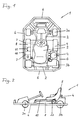
- Fig. 1 shows schematically in a highly simplified representation a top view of a Motor card, which as a whole is provided with the reference number 1.
- a vehicle frame 2 which is essentially a flat, welded Tubular frame is formed, carries the chassis with the steerably suspended Front wheels 3a and rear wheels 3b, which are powered by an internal combustion engine 4 are driven, which laterally on the vehicle frame 2 in the direction of travel is mounted, essentially next to the driver's seat 5.
- This is preferably designed as a bucket seat, which is centrally located on the top of the Vehicle frame 2 is attached.
- All-round bumpers 6 are attached to the outside of the vehicle frame 2, which in turn form a closed all-round protection that covers the entire Surrounds motor card 1 on the outside.
- the attachment to the vehicle frame 2 takes place via screwed or welded struts 7.
- a fuel tank 8 is in the middle area between the Front wheel 3a and rear wheel 3b on the left in the drawing between the vehicle frame 2 and the bumper 6 running laterally there appropriate.
- the attachment can take place on the struts 7 running there.
- the fuel tank 8 can be a cuboid or box-shaped sheet metal or Be plastic tank. It can preferably be in a side box 9 be housed, which also on the right in the drawing can be attached and only serves as a panel there.
- the attachment of the Fuel tanks 8 can be seen at the level of the vehicle frame 2, specifically from the Seen from the side behind the bumper 6 or the safety bracket 10.
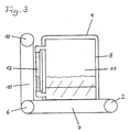
- FIG 3 is another sectional view through the fuel tank 8 shown, which is housed in a side box 9 and on a strut 7th is mounted between the vehicle frame 2 and the side bumper 6.
- a special feature of this fuel tank 8 is that in its interior Baffles 11 are welded in transverse to the direction of travel. This extend from the top of the tank to just below the bottom. Thereby It is avoided that the gasoline contained in the tank 8 when braking and Do not accelerate back and forth in an uncontrolled manner, which makes Vehicle could be destabilized.
- the fuel tank 8 also has a level measuring device with a Viewing tube 12, which is made of transparent, fuel-resistant plastic exists and is standing vertically on the outside, it being in upper and lower area is connected to the inside of the tank. According to the principle the communicating tubes appear in this viewing tube Liquid level which corresponds to the current fuel level in the fuel tank 8 equivalent. This makes it easy to read from the outside.
Landscapes
- Engineering & Computer Science (AREA)
- Chemical & Material Sciences (AREA)
- Combustion & Propulsion (AREA)
- Transportation (AREA)
- Mechanical Engineering (AREA)
- Life Sciences & Earth Sciences (AREA)
- Sustainable Development (AREA)
- Sustainable Energy (AREA)
- Cooling, Air Intake And Gas Exhaust, And Fuel Tank Arrangements In Propulsion Units (AREA)
- Electrical Discharge Machining, Electrochemical Machining, And Combined Machining (AREA)
- Ticket-Dispensing Machines (AREA)
- Magnetic Resonance Imaging Apparatus (AREA)
Abstract
Description
- Fig. 1
- eine schematische Ansicht von oben auf ein erfindungsgemäßes Motorkart;
- Fig. 2
- eine Seitenansicht des Motorkarts gemäß Fig. 1;
- Fig. 3
- eine Schnittdarstellung durch den Treibstofftank gemäß Fig. 1.
Claims (11)
- Motorkart mit einem Fahrzeugrahmen, welcher das Fahrwerk, einen Verbrennungsmotor als Antriebsmaschine sowie den Treibstofftank trägt und auf dem ein Fahrersitz angebracht ist, und an dem zumindest teilweise außen umlaufende Stoßstangen angebracht sind, dadurch gekennzeichnet, dass der Treibstofftank (8) seitlich zwischen dem Fahrzeugrahmen und einer seitlich verlaufenden Stoßstange (6) untergebracht ist.
- Motorkart nach Anspruch 1, dadurch gekennzeichnet, dass der Treibstofftank (8) in einem Seitenkasten (9) integriert ist.
- Motorkart nach Anspruch 1, dadurch gekennzeichnet, dass ein Seitenkasten (9) als Treibstofftank (8) ausgebildet ist.
- Motorkart nach einem der Ansprüche 1 bis 3, dadurch gekennzeichnet, dass der Treibstofftank (8) eine längliche Bauform hat.
- Motorkart nach einem der Ansprüche 1 bis 4, dadurch gekennzeichnet, dass der Treibstofftank (8) im wesentlichen quaderförmig ausgebildet ist.
- Motorkart nach einem der Ansprüche 1 bis 5, dadurch gekennzeichnet, dass der Treibstofftank (8) auf Verbindungsstreben (7) zwischen der Stoßstange (6) und dem Fahrzeugrahmen (2) befestigt ist.
- Motorkart nach einem der Ansprüche 1 bis 6, dadurch gekennzeichnet, dass die seitlich verlaufende Stoßstange (geschlossener Rundumschutz 6) im Bereich des Treibstofftanks erhöht ist.
- Motorkart nach einem der Ansprüche 1 bis 7, dadurch gekennzeichnet, dass die seitlich verlaufende Stoßstange (6) im Bereich des Treibstofftanks (8) verstärkt ist.
- Motorkart nach einem der Ansprüche 1 bis 8, dadurch gekennzeichnet, dass in dem Treibstofftank (8) quer zur Fahrtrichtung Schwallbleche (11)
- Motorkart nach einem der Ansprüche 1 bis 9, dadurch gekennzeichnet, dass der Treibstofftank (8) schwingungsgedämpft am Fahrzeugrahmen (2) angebracht ist.
- Motorkart nach einem der Ansprüche 1 bis 10, dadurch gekennzeichnet, dass der Treibstofftank (8) eine Füllstandsanzeigeeinrichtung hat mit einem außen angebrachten transparenten Schaurohr (12), welches im oberen und unteren Bereich mit dem Tankinnenraum verbunden ist.
Priority Applications (1)
| Application Number | Priority Date | Filing Date | Title |
|---|---|---|---|
| DE20220245U DE20220245U1 (de) | 2001-05-04 | 2002-04-12 | Motorkart |
Applications Claiming Priority (2)
| Application Number | Priority Date | Filing Date | Title |
|---|---|---|---|
| DE20107609U DE20107609U1 (de) | 2001-05-04 | 2001-05-04 | Motorkart |
| DE20107609U | 2001-05-04 |
Publications (3)
| Publication Number | Publication Date |
|---|---|
| EP1254802A2 true EP1254802A2 (de) | 2002-11-06 |
| EP1254802A3 EP1254802A3 (de) | 2004-07-14 |
| EP1254802B1 EP1254802B1 (de) | 2007-02-21 |
Family
ID=7956505
Family Applications (1)
| Application Number | Title | Priority Date | Filing Date |
|---|---|---|---|
| EP02008344A Expired - Lifetime EP1254802B1 (de) | 2001-05-04 | 2002-04-12 | Go-Kart |
Country Status (3)
| Country | Link |
|---|---|
| EP (1) | EP1254802B1 (de) |
| AT (1) | ATE354491T1 (de) |
| DE (2) | DE20107609U1 (de) |
Families Citing this family (1)
| Publication number | Priority date | Publication date | Assignee | Title |
|---|---|---|---|---|
| DE202009016233U1 (de) | 2009-11-27 | 2010-11-11 | Sommer, Maik | Sportgerät |
Family Cites Families (9)
| Publication number | Priority date | Publication date | Assignee | Title |
|---|---|---|---|---|
| US3096842A (en) * | 1959-09-02 | 1963-07-09 | George A Westmont | Driving and weight distribution arrangement for self-propelled golf carts |
| DE3416270A1 (de) | 1984-05-03 | 1985-11-14 | Deere & Co., Moline, Ill., US, Niederlassung Deere & Co. European Office, 6800 Mannheim | Anordnung eines behaelters an einem fahrzeug |
| JP2564920B2 (ja) * | 1988-11-25 | 1996-12-18 | 株式会社豊田自動織機製作所 | 産業車両の車体構造 |
| DE4012427A1 (de) | 1990-04-19 | 1990-08-23 | Horst Gorny | Maehfahrzeug zur bearbeitung stark geneigter flaechen |
| FR2661646A1 (fr) * | 1990-05-02 | 1991-11-08 | Savard Franck | Kart a moteur central et chassis a reglage multiples. |
| GB9506266D0 (en) * | 1995-03-28 | 1995-06-14 | Bashall Christopher | Improved vehicle |
| DE29700456U1 (de) * | 1997-01-13 | 1998-02-05 | Vöhringer, Hans-Christoph, 72805 Lichtenstein | Hubmatic-Rundumschutz für ein Go-Kart im Heckbereich 2-fach drehbar gelagert |
| DE19707947C2 (de) | 1997-02-27 | 1999-08-26 | Wuensche | Abdeckung für rotierende Teile und Go-Kart-Wagen mit einer derartigen Abdeckung |
| DE19919560A1 (de) * | 1999-04-29 | 2000-11-02 | Volkswagen Ag | Kraftfahrzeug mit Mittenbereich und Endbereichen |
-
2001
- 2001-05-04 DE DE20107609U patent/DE20107609U1/de not_active Expired - Lifetime
-
2002
- 2002-04-12 AT AT02008344T patent/ATE354491T1/de not_active IP Right Cessation
- 2002-04-12 EP EP02008344A patent/EP1254802B1/de not_active Expired - Lifetime
- 2002-04-12 DE DE50209510T patent/DE50209510D1/de not_active Expired - Fee Related
Non-Patent Citations (1)
| Title |
|---|
| None |
Also Published As
| Publication number | Publication date |
|---|---|
| EP1254802B1 (de) | 2007-02-21 |
| EP1254802A3 (de) | 2004-07-14 |
| DE50209510D1 (de) | 2007-04-05 |
| DE20107609U1 (de) | 2001-08-09 |
| ATE354491T1 (de) | 2007-03-15 |
Similar Documents
| Publication | Publication Date | Title |
|---|---|---|
| EP2684775B1 (de) | Rahmentragstruktur mit Tankeinrichtung | |
| EP0591715A2 (de) | Nutzfahrzeug, insbesondere Frontlenker-Lastkraftwagen | |
| DE102016005264B4 (de) | Rohbau eines Kraftfahrzeugs | |
| DE1011740B (de) | Karosserie fuer Zugmaschinen | |
| DE2756342C2 (de) | ||
| DE2056713A1 (de) | Kraftfahrzeugrahmen | |
| EP3616954B1 (de) | Lastkraftwagen mit einer elektrischen antriebseinheit | |
| DE19860238A1 (de) | Einsatzfahrzeug für Rettungsdienste | |
| DE4030740A1 (de) | Heckteil einer autokarosserie | |
| DE3340973C2 (de) | ||
| EP1254802B1 (de) | Go-Kart | |
| DE4234143A1 (de) | Nutzfahrzeug, insbesondere Frontlenker-Lastkraftwagen mit Rundum-Knautschzonen | |
| DE10148215B4 (de) | System zum Aufbau eines Fahrgestells für Nutzfahrzeuge | |
| DE2063320C3 (de) | Schlepper selbsttragender Bauweise mit einem Fahrersitz und einem Überschlagschutz | |
| DE4413412A1 (de) | Omnibus | |
| DE3808314C1 (de) | ||
| DE102014018343A1 (de) | Integralträger für Antriebsenergie-Komponenten eines Kraftfahrzeugs | |
| DE102004054853A1 (de) | Achsanordnung für einen Kraftwagen | |
| DE20220245U1 (de) | Motorkart | |
| DE3517287A1 (de) | Fahrgestell fuer ein einsatzfahrzeug, insbesondere feuerwehrfahrzeug | |
| EP0591727B1 (de) | Nutzfahrzeug, insbesondere Frontlenker-Lastkraftwagen | |
| DE19537573C2 (de) | Allrad-Kfz | |
| DE60112490T2 (de) | Vorrichtung an Hubwagen mit Gegengewicht | |
| DE19809214A1 (de) | Fahrgestell eines schweren Nutzfahrzeuges | |
| DE19809196A1 (de) | Fahrgestell eines schweren Nutzfahrzeuges |
Legal Events
| Date | Code | Title | Description |
|---|---|---|---|
| PUAI | Public reference made under article 153(3) epc to a published international application that has entered the european phase |
Free format text: ORIGINAL CODE: 0009012 |
|
| AK | Designated contracting states |
Kind code of ref document: A2 Designated state(s): AT BE CH CY DE DK ES FI FR GB GR IE IT LI LU MC NL PT SE TR |
|
| AX | Request for extension of the european patent |
Free format text: AL;LT;LV;MK;RO;SI |
|
| PUAL | Search report despatched |
Free format text: ORIGINAL CODE: 0009013 |
|
| AK | Designated contracting states |
Kind code of ref document: A3 Designated state(s): AT BE CH CY DE DK ES FI FR GB GR IE IT LI LU MC NL PT SE TR |
|
| AX | Request for extension of the european patent |
Extension state: AL LT LV MK RO SI |
|
| RIC1 | Information provided on ipc code assigned before grant |
Ipc: 7B 60K 15/063 A Ipc: 7B 62D 21/18 B |
|
| 17P | Request for examination filed |
Effective date: 20050114 |
|
| AKX | Designation fees paid |
Designated state(s): AT BE CH CY DE DK ES FI FR GB GR IE IT LI LU MC NL PT SE TR |
|
| AXX | Extension fees paid |
Extension state: SI Payment date: 20050114 Extension state: AL Payment date: 20050114 Extension state: LV Payment date: 20050114 Extension state: LT Payment date: 20050114 Extension state: MK Payment date: 20050114 Extension state: RO Payment date: 20050114 |
|
| GRAP | Despatch of communication of intention to grant a patent |
Free format text: ORIGINAL CODE: EPIDOSNIGR1 |
|
| GRAS | Grant fee paid |
Free format text: ORIGINAL CODE: EPIDOSNIGR3 |
|
| GRAA | (expected) grant |
Free format text: ORIGINAL CODE: 0009210 |
|
| AK | Designated contracting states |
Kind code of ref document: B1 Designated state(s): AT BE CH CY DE DK ES FI FR GB GR IE IT LI LU MC NL PT SE TR |
|
| AX | Request for extension of the european patent |
Extension state: AL LT LV MK RO SI |
|
| PG25 | Lapsed in a contracting state [announced via postgrant information from national office to epo] |
Ref country code: FI Free format text: LAPSE BECAUSE OF FAILURE TO SUBMIT A TRANSLATION OF THE DESCRIPTION OR TO PAY THE FEE WITHIN THE PRESCRIBED TIME-LIMIT Effective date: 20070221 Ref country code: DK Free format text: LAPSE BECAUSE OF FAILURE TO SUBMIT A TRANSLATION OF THE DESCRIPTION OR TO PAY THE FEE WITHIN THE PRESCRIBED TIME-LIMIT Effective date: 20070221 Ref country code: NL Free format text: LAPSE BECAUSE OF FAILURE TO SUBMIT A TRANSLATION OF THE DESCRIPTION OR TO PAY THE FEE WITHIN THE PRESCRIBED TIME-LIMIT Effective date: 20070221 Ref country code: IE Free format text: LAPSE BECAUSE OF FAILURE TO SUBMIT A TRANSLATION OF THE DESCRIPTION OR TO PAY THE FEE WITHIN THE PRESCRIBED TIME-LIMIT Effective date: 20070221 |
|
| REG | Reference to a national code |
Ref country code: GB Ref legal event code: FG4D Free format text: NOT ENGLISH |
|
| REG | Reference to a national code |
Ref country code: CH Ref legal event code: EP |
|
| REF | Corresponds to: |
Ref document number: 50209510 Country of ref document: DE Date of ref document: 20070405 Kind code of ref document: P |
|
| REG | Reference to a national code |
Ref country code: IE Ref legal event code: FG4D Free format text: LANGUAGE OF EP DOCUMENT: GERMAN |
|
| PG25 | Lapsed in a contracting state [announced via postgrant information from national office to epo] |
Ref country code: SE Free format text: LAPSE BECAUSE OF FAILURE TO SUBMIT A TRANSLATION OF THE DESCRIPTION OR TO PAY THE FEE WITHIN THE PRESCRIBED TIME-LIMIT Effective date: 20070521 |
|
| PG25 | Lapsed in a contracting state [announced via postgrant information from national office to epo] |
Ref country code: ES Free format text: LAPSE BECAUSE OF FAILURE TO SUBMIT A TRANSLATION OF THE DESCRIPTION OR TO PAY THE FEE WITHIN THE PRESCRIBED TIME-LIMIT Effective date: 20070601 |
|
| GBT | Gb: translation of ep patent filed (gb section 77(6)(a)/1977) |
Effective date: 20070515 |
|
| PG25 | Lapsed in a contracting state [announced via postgrant information from national office to epo] |
Ref country code: PT Free format text: LAPSE BECAUSE OF FAILURE TO SUBMIT A TRANSLATION OF THE DESCRIPTION OR TO PAY THE FEE WITHIN THE PRESCRIBED TIME-LIMIT Effective date: 20070723 |
|
| LTIE | Lt: invalidation of european patent or patent extension |
Effective date: 20070221 |
|
| NLV1 | Nl: lapsed or annulled due to failure to fulfill the requirements of art. 29p and 29m of the patents act | ||
| ET | Fr: translation filed | ||
| REG | Reference to a national code |
Ref country code: IE Ref legal event code: FD4D |
|
| REG | Reference to a national code |
Ref country code: CH Ref legal event code: PL |
|
| PLBE | No opposition filed within time limit |
Free format text: ORIGINAL CODE: 0009261 |
|
| STAA | Information on the status of an ep patent application or granted ep patent |
Free format text: STATUS: NO OPPOSITION FILED WITHIN TIME LIMIT |
|
| BERE | Be: lapsed |
Owner name: RIMO TRANSPORTGERATE G.M.B.H. & CO. KG Effective date: 20070430 |
|
| 26N | No opposition filed |
Effective date: 20071122 |
|
| PG25 | Lapsed in a contracting state [announced via postgrant information from national office to epo] |
Ref country code: LI Free format text: LAPSE BECAUSE OF NON-PAYMENT OF DUE FEES Effective date: 20070430 Ref country code: CH Free format text: LAPSE BECAUSE OF NON-PAYMENT OF DUE FEES Effective date: 20070430 |
|
| PG25 | Lapsed in a contracting state [announced via postgrant information from national office to epo] |
Ref country code: BE Free format text: LAPSE BECAUSE OF NON-PAYMENT OF DUE FEES Effective date: 20070430 |
|
| PG25 | Lapsed in a contracting state [announced via postgrant information from national office to epo] |
Ref country code: IT Free format text: LAPSE BECAUSE OF FAILURE TO SUBMIT A TRANSLATION OF THE DESCRIPTION OR TO PAY THE FEE WITHIN THE PRESCRIBED TIME-LIMIT Effective date: 20070221 Ref country code: GR Free format text: LAPSE BECAUSE OF FAILURE TO SUBMIT A TRANSLATION OF THE DESCRIPTION OR TO PAY THE FEE WITHIN THE PRESCRIBED TIME-LIMIT Effective date: 20070522 |
|
| PGFP | Annual fee paid to national office [announced via postgrant information from national office to epo] |
Ref country code: GB Payment date: 20080320 Year of fee payment: 7 |
|
| PGFP | Annual fee paid to national office [announced via postgrant information from national office to epo] |
Ref country code: DE Payment date: 20080430 Year of fee payment: 7 Ref country code: FR Payment date: 20080313 Year of fee payment: 7 |
|
| PG25 | Lapsed in a contracting state [announced via postgrant information from national office to epo] |
Ref country code: AT Free format text: LAPSE BECAUSE OF NON-PAYMENT OF DUE FEES Effective date: 20070412 |
|
| PG25 | Lapsed in a contracting state [announced via postgrant information from national office to epo] |
Ref country code: MC Free format text: LAPSE BECAUSE OF NON-PAYMENT OF DUE FEES Effective date: 20070430 |
|
| PG25 | Lapsed in a contracting state [announced via postgrant information from national office to epo] |
Ref country code: CY Free format text: LAPSE BECAUSE OF FAILURE TO SUBMIT A TRANSLATION OF THE DESCRIPTION OR TO PAY THE FEE WITHIN THE PRESCRIBED TIME-LIMIT Effective date: 20070221 |
|
| PG25 | Lapsed in a contracting state [announced via postgrant information from national office to epo] |
Ref country code: LU Free format text: LAPSE BECAUSE OF NON-PAYMENT OF DUE FEES Effective date: 20070412 |
|
| PG25 | Lapsed in a contracting state [announced via postgrant information from national office to epo] |
Ref country code: TR Free format text: LAPSE BECAUSE OF FAILURE TO SUBMIT A TRANSLATION OF THE DESCRIPTION OR TO PAY THE FEE WITHIN THE PRESCRIBED TIME-LIMIT Effective date: 20070221 |
|
| GBPC | Gb: european patent ceased through non-payment of renewal fee |
Effective date: 20090412 |
|
| REG | Reference to a national code |
Ref country code: FR Ref legal event code: ST Effective date: 20091231 |
|
| PG25 | Lapsed in a contracting state [announced via postgrant information from national office to epo] |
Ref country code: DE Free format text: LAPSE BECAUSE OF NON-PAYMENT OF DUE FEES Effective date: 20091103 |
|
| PG25 | Lapsed in a contracting state [announced via postgrant information from national office to epo] |
Ref country code: GB Free format text: LAPSE BECAUSE OF NON-PAYMENT OF DUE FEES Effective date: 20090412 Ref country code: FR Free format text: LAPSE BECAUSE OF NON-PAYMENT OF DUE FEES Effective date: 20091222 |