EP1255116A1 - Ein Lager und ein Messgerät enthaltende Vorrichtung sowie ein mit einem Monoblock-Sensor verbundenes Gehäuse - Google Patents
Ein Lager und ein Messgerät enthaltende Vorrichtung sowie ein mit einem Monoblock-Sensor verbundenes Gehäuse Download PDFInfo
- Publication number
- EP1255116A1 EP1255116A1 EP02291042A EP02291042A EP1255116A1 EP 1255116 A1 EP1255116 A1 EP 1255116A1 EP 02291042 A EP02291042 A EP 02291042A EP 02291042 A EP02291042 A EP 02291042A EP 1255116 A1 EP1255116 A1 EP 1255116A1
- Authority
- EP
- European Patent Office
- Prior art keywords
- bearing
- housing
- sensor
- assembly according
- ring
- Prior art date
- Legal status (The legal status is an assumption and is not a legal conclusion. Google has not performed a legal analysis and makes no representation as to the accuracy of the status listed.)
- Withdrawn
Links
- 210000002105 tongue Anatomy 0.000 claims description 14
- 230000000295 complement effect Effects 0.000 claims description 6
- 239000000463 material Substances 0.000 claims description 4
- 238000005096 rolling process Methods 0.000 claims description 4
- 230000005355 Hall effect Effects 0.000 claims description 2
- 230000005415 magnetization Effects 0.000 claims description 2
- 239000002245 particle Substances 0.000 claims description 2
- 230000002093 peripheral effect Effects 0.000 claims description 2
- 239000000523 sample Substances 0.000 claims description 2
- 229920002994 synthetic fiber Polymers 0.000 claims description 2
- 229910000859 α-Fe Inorganic materials 0.000 claims description 2
- 230000000903 blocking effect Effects 0.000 abstract description 11
- 238000013481 data capture Methods 0.000 abstract 2
- 230000000712 assembly Effects 0.000 description 3
- 238000000429 assembly Methods 0.000 description 3
- 238000007789 sealing Methods 0.000 description 3
- 239000000314 lubricant Substances 0.000 description 2
- 238000003754 machining Methods 0.000 description 2
- 208000031968 Cadaver Diseases 0.000 description 1
- 230000000694 effects Effects 0.000 description 1
- 229920001971 elastomer Polymers 0.000 description 1
- 239000000806 elastomer Substances 0.000 description 1
- 239000003344 environmental pollutant Substances 0.000 description 1
- 230000002427 irreversible effect Effects 0.000 description 1
- 238000004519 manufacturing process Methods 0.000 description 1
- 238000000465 moulding Methods 0.000 description 1
- 210000000056 organ Anatomy 0.000 description 1
- 231100000719 pollutant Toxicity 0.000 description 1
- 239000007787 solid Substances 0.000 description 1
Images

Classifications
-
- F—MECHANICAL ENGINEERING; LIGHTING; HEATING; WEAPONS; BLASTING
- F16—ENGINEERING ELEMENTS AND UNITS; GENERAL MEASURES FOR PRODUCING AND MAINTAINING EFFECTIVE FUNCTIONING OF MACHINES OR INSTALLATIONS; THERMAL INSULATION IN GENERAL
- F16C—SHAFTS; FLEXIBLE SHAFTS; ELEMENTS OR CRANKSHAFT MECHANISMS; ROTARY BODIES OTHER THAN GEARING ELEMENTS; BEARINGS
- F16C35/00—Rigid support of bearing units; Housings, e.g. caps, covers
- F16C35/04—Rigid support of bearing units; Housings, e.g. caps, covers in the case of ball or roller bearings
- F16C35/06—Mounting or dismounting of ball or roller bearings; Fixing them onto shaft or in housing
- F16C35/067—Fixing them in a housing
-
- B—PERFORMING OPERATIONS; TRANSPORTING
- B62—LAND VEHICLES FOR TRAVELLING OTHERWISE THAN ON RAILS
- B62D—MOTOR VEHICLES; TRAILERS
- B62D1/00—Steering controls, i.e. means for initiating a change of direction of the vehicle
- B62D1/02—Steering controls, i.e. means for initiating a change of direction of the vehicle vehicle-mounted
- B62D1/16—Steering columns
-
- B—PERFORMING OPERATIONS; TRANSPORTING
- B62—LAND VEHICLES FOR TRAVELLING OTHERWISE THAN ON RAILS
- B62D—MOTOR VEHICLES; TRAILERS
- B62D15/00—Steering not otherwise provided for
- B62D15/02—Steering position indicators ; Steering position determination; Steering aids
- B62D15/021—Determination of steering angle
- B62D15/0215—Determination of steering angle by measuring on the steering column
-
- F—MECHANICAL ENGINEERING; LIGHTING; HEATING; WEAPONS; BLASTING
- F16—ENGINEERING ELEMENTS AND UNITS; GENERAL MEASURES FOR PRODUCING AND MAINTAINING EFFECTIVE FUNCTIONING OF MACHINES OR INSTALLATIONS; THERMAL INSULATION IN GENERAL
- F16C—SHAFTS; FLEXIBLE SHAFTS; ELEMENTS OR CRANKSHAFT MECHANISMS; ROTARY BODIES OTHER THAN GEARING ELEMENTS; BEARINGS
- F16C19/00—Bearings with rolling contact, for exclusively rotary movement
- F16C19/52—Bearings with rolling contact, for exclusively rotary movement with devices affected by abnormal or undesired conditions
-
- G—PHYSICS
- G01—MEASURING; TESTING
- G01P—MEASURING LINEAR OR ANGULAR SPEED, ACCELERATION, DECELERATION, OR SHOCK; INDICATING PRESENCE, ABSENCE, OR DIRECTION, OF MOVEMENT
- G01P3/00—Measuring linear or angular speed; Measuring differences of linear or angular speeds
- G01P3/42—Devices characterised by the use of electric or magnetic means
- G01P3/44—Devices characterised by the use of electric or magnetic means for measuring angular speed
- G01P3/443—Devices characterised by the use of electric or magnetic means for measuring angular speed mounted in bearings
-
- F—MECHANICAL ENGINEERING; LIGHTING; HEATING; WEAPONS; BLASTING
- F16—ENGINEERING ELEMENTS AND UNITS; GENERAL MEASURES FOR PRODUCING AND MAINTAINING EFFECTIVE FUNCTIONING OF MACHINES OR INSTALLATIONS; THERMAL INSULATION IN GENERAL
- F16C—SHAFTS; FLEXIBLE SHAFTS; ELEMENTS OR CRANKSHAFT MECHANISMS; ROTARY BODIES OTHER THAN GEARING ELEMENTS; BEARINGS
- F16C2326/00—Articles relating to transporting
- F16C2326/20—Land vehicles
- F16C2326/24—Steering systems, e.g. steering rods or columns
Definitions
- the invention relates to an assembly comprising a bearing fitted with a information sensor device and a housing inside which said bearing is fitted.
- such assemblies allow the rotation of an organ. rotating by associating it with the rotating ring and on the other hand blocking in position of the bearing and of the member with respect to the housing.
- the invention also relates to a vehicle steering system.
- automobile comprising a steering column fitted into the ring interior of such an assembly and a head tube in which the housing is formed to receive said column in rotation.
- the bearing when the bearing is fitted with a sensor device speed, angular position and / or direction of rotation of the rotating ring with respect to the fixed ring, the information can be converted into signals depending on the torque exerted on the column by via the steering wheel, said signals being used by a computer management assistance.
- such assemblies are used for motor vehicle wheels which are fitted with an anti-lock system said wheels, and the information is then used in particular by a brake assist computer.
- bearings equipped with an information sensor device which includes a magnetic pulse generator encoder associated with the rotating ring and, associated with the fixed ring, a sensor provided with at least two sensitive elements capable of detecting these impulses.
- a fixing device comprising a socket provided with projections, said socket being fitted on the outer ring of the bearing with the projections arranged inside a groove provided in the housing.
- the sleeve carries the sensor.
- This embodiment has many drawbacks.
- this embodiment does not ensure sufficient fixing safe rolling inside the housing. Indeed, the fixation is ensured only by a mounting span on which all the efforts undergone by rollover apply.
- this embodiment does not not precise positioning of the sensor relative to the encoder.
- the senor in particular for security uses such as anti-blocking of wheels or steering assistance, the sensor must be secured to the bearing precisely and safely so that sensitive items are always in gaze and air gap distance from the encoder.
- the invention therefore aims in particular to remedy these drawbacks by proposing an assembly in which the sensor is made in one piece with means for blocking the bearing inside the housing, said means ensuring secure blocking of the bearing with sensitive sensor elements precisely and securely arranged opposite and at air gap from the encoder.
- the invention proposes a steering system for motor vehicle comprising a steering column fitted into the inner ring of such an assembly and a head tube receiving said rotating column, in which the housing is formed in the tube.
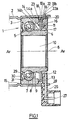
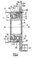
- FIG. 1 to 3 an assembly comprising a bearing 1 equipped with an information sensor device and a housing 2 inside which said bearing 1 is associated by fitting.
- the bearing includes a fixed outer ring 3 fitted in the housing 2, a rotating inner ring 4 and rolling bodies 5 arranged between them in order to allow the relative rotation of these two rings around a axis 6.
- bearing 1 is force-fitted in the housing 2 with the upper face of the fixed ring 3 associated with the face interior of housing 2.
- the terms “exterior” and “interior” are defined by relative to a plane respectively opposite and opposite axis 6, the terms “Axial” or “transverse” are defined with respect to a plane parallel to axis 6, the terms “radial” or “lateral” are defined with respect to a plane perpendicular to axis 6, the terms “front” and “rear” are defined by compared to the indices av and ar placed in the figures, the dimensions measured along axis 6 or perpendicular to it are said to be “axial” respectively and "radial”.
- a raceway 7, 8 is produced respectively on the inner face of the fixed ring 3 and on the face outside of the rotating ring 4, and the bearing is provided by a row balls 5 which are held equidistant by a cage 9.
- Such bearings 1 are for example used to ensure the rotation of a steering column or that of the wheels of a motor vehicle.
- the inner ring 4 has a bore 10 intended to accommodate the column of direction or the wheel hub.
- an information sensor device comprising an encoder 11 magnetic pulse generator associated with the rotating ring 4 and, associated with the fixed ring 3, a sensor 12 provided with at least two elements sensitive 13 able to detect these impulses.
- This type of information after electronic processing such as for example that described in document FR-2 792 380, is conventionally used in driver assistance systems such as steering assistance or wheel anti-lock systems.
- the encoder 11 is formed of a multipolar ring made of synthetic material loaded with ferrite particles formed of a plurality of contiguous domains with reverse magnetization direction of a domain given by in relation to the two adjoining areas.
- the encoder 11 is molded onto a cylindrical annular and radial bearing 14a of an armature 14.
- the armature 14 also includes an annular and axial cylindrical seat 14b which is associated, for example by fitting, on the outer face of the ring interior 4. This embodiment allows the joint rotation of the encoder 11 and the inner ring 4.
- the housing 2 is cylindrical with an inside diameter substantially equal to the outside diameter of the ring outer 3 to allow fitting while ensuring radial locking of the bearing 1 inside the housing 2.
- the housing 2 is formed in a head tube so as to be integrated into it, and the bearing 1 allows the axial and radial locking as well as the rotation of a steering column inside this tube.
- the housing 2 can either be formed of a section of tube or be produced in a section of tube, for example by machining or deformation of this one.
- the housing 2 has first means of axial locking of the bearing 1 in a direction which are formed by a shoulder 15 whose internal diameter is smaller than the outside diameter of the outer ring 3.
- the senor 12 comprises at least two elements sensitive 13, for example a plurality of aligned sensitive elements, which are chosen from Hall effect probes, magnetoresistors, giant magnetoresistors.
- elements are capable of detect the magnetic pulses generated by the encoder 11 so as to provide signals for example representative of the speed of rotation, the direction of movement and / or of the angular position of the rotating ring 4 by fixed ring ratio 3.
- the senor 12 is formed of a ring 16 concentric with the bearing 1 and a bore 17 is formed in the ring 16 so that it does not interfere with the rotation of the ring rotating 4.
- the ring 16 also includes a peripheral extension 18 extending axially forward.
- the sensor 12 is produced in a single piece, for example by molding a plastic material, with the sensitive elements 13 arranged in the mass of the ring 16.
- the sensor 12 further comprises, integrated, second blocking means of the bearing 1, said second means being arranged to cooperate with additional means provided on the housing 2 so as to ensure the blocking of bearing 1 at least towards the rear.
- the second blocking means include a plurality of elastic tabs 19 which are regularly arranged on the external transverse face of the sensor 12.
- the tongues 19 are formed so as to be associated with the sensor 12 by their rear edge 19a with their front end 19b projecting radially outward from the surface of said sensor 12.
- the tongues 19 are capable of being folded down substantially in the plane of the sensor 12 to allow the fitting of the bearing 1 into the housing 2, then redeploy radially due to the elasticity of the material forming the sensor 12.
- the tongues 19 are provided for continue the extension 18 axially towards the rear, extending radially from the transverse outer surface of said extension 18.
- a bevel 20 is provided on the face external transverse of the ring 16, at least opposite the tabs 19.
- the tongues 19 are identical to those of the first embodiment but a beveled housing 21 is provided respectively opposite the tabs 19 to allow their folding when the bearing 1 is introduced into the housing 2.
- the complementary means are formed of recesses 22 arranged to respectively receive said tabs 19 deployed radially, said recesses 22 being regularly distributed over the housing 2.
- the axial blocking between the front end 19b a tongue 19 and the rear lateral face 22a of a recess 22 makes it possible to lock the bearing 1 inside the housing 2 forwards.
- the tongues 19 When the bearing 1 is introduced into the housing 2, the tongues 19 come into contact with the inner face of the housing 2 which causes them to radial drawdown and thus allows fitting, then, when the tabs 19 are opposite the recesses 22, they deploy to allow axial locking of the bearing 1.
- the distance between the shoulder 15 and the recesses 22 is arranged to axially lock the bearing 1 and the sensor 12 without play, with the elements 13 substantially opposite and at air gap distance from encoder 12.
- the respective widths of the tongues 19 and of the recesses 22 can be substantially equal so as to ensure a rotation lock of the bearing 1 inside the housing 2.
- the complementary means are formed of an annular groove formed on the inner face of the housing so as to receive the tongues 19 deployed radially allowing a axial locking between the front end of the tabs and the rear side face of the groove.
- the fitting of the bearing 1 inside the housing 2 is produced in an almost irreversible manner since it prohibits any return to rear of bearing 1.
- the length of the extension 17 is arranged for, coming to bear on the front side face 23 of the fixed ring 3, allow the positioning of the sensitive elements 13 opposite and at air gap distance from encoder 11.
- the front side face 23 does not include any specific machining for allow the holding or positioning of the sensor 12 with the elements sensitive 13 at air gap distance from encoder 11.
- the axial locking of the bearing 1 and of the sensor 12 towards the rear is provided between the front side face 23 and the rear side face of the extension 17.
- the sensor 12 forms an axial stop for the bearing 1.
- the senor 12 and the ring external 3 include means of reciprocal association.
- the association means comprise fingers 24 extending axially towards the rear of the extension 18 and a groove 25 arranged on the transverse face outside of the fixed ring 3 for receiving said fingers 24 by arranging the sensitive elements 13 facing and at air gap distance from the encoder 11.
- the senor 12 prior to the introduction of the bearing 1 into the housing 2, the sensor 12 is associated with the fixed ring 3, then the assembly is introduced into the slot 2 to be blocked.
- the blocking force is transmitted between the sensor 12 and the outer ring 3 via the association means, the sensor 12 also forming an axial stop for the bearing 1.
- the senor 12 comprises a radial housing 26 arranged to receive the input / output connectors 27 of the sensor 12, for example formed by a connector or a multi-wire cable.
- the housing 2 then comprises an axial cutout 28 whose size is arranged to receive the radial housing 26 by ensuring a rotation lock of the bearing 1 inside the housing 1.
- this embodiment makes it possible to index the introduction of the bearing 1 to the interior of the housing 2 by placing the tabs 19 opposite the recesses 22.
- the assembly according to the invention therefore allows, safely and without parts additional, on the one hand to ensure an axial, radial and rotational locking of the bearing 1 inside the housing 2 and on the other hand to ensure the association of the sensor 12 on the bearing 1 with the sensitive elements 13 facing and air gap distance from encoder 11.
- the blocking force applied is only limited by the resistance of the sensor material 12 since it forms a mechanical stop on the bearing 1, and on the other hand any relative movement of the sensor 12 relative to to the outer ring 3 and therefore relative to the encoder 11 is prevented.
- the tightness of the bearing 1 is provided on the rear face by an elastomer lip 29 which rubs on the inner ring 4.
- the lip 29 is molded onto a associated frame 30, for example by clipping, in a groove 31 provided on the inner face of the outer ring 3.
- the front panel is sealed thanks to the relative arrangement of the frame 14 and the ring 16. In fact, these form a baffle which helps prevent bearing pollution and lubricant leakage.
- the sensor 12 makes it possible to protect the encoder 11 by facing it on the assembly of its periphery in order to limit the progression of pollutants.
- the cages include axial extensions rubbing on the rings to serve deflectors or, in particular for bearings for movements alternatives, to use a solid lubricant as described in document FR-2 760,055.
- a sealing lip such that described above can be used to rub on the litter of the armature.
Landscapes
- Engineering & Computer Science (AREA)
- Mechanical Engineering (AREA)
- General Engineering & Computer Science (AREA)
- Chemical & Material Sciences (AREA)
- Combustion & Propulsion (AREA)
- Transportation (AREA)
- Physics & Mathematics (AREA)
- General Physics & Mathematics (AREA)
- Mounting Of Bearings Or Others (AREA)
- Transmission And Conversion Of Sensor Element Output (AREA)
- Steering Controls (AREA)
- Force Measurement Appropriate To Specific Purposes (AREA)
Applications Claiming Priority (2)
| Application Number | Priority Date | Filing Date | Title |
|---|---|---|---|
| FR0106021A FR2824368B1 (fr) | 2001-05-04 | 2001-05-04 | Ensemble comprenant un roulement instrumente et un logement associes par un capteur monobloc |
| FR0106021 | 2001-05-04 |
Publications (1)
| Publication Number | Publication Date |
|---|---|
| EP1255116A1 true EP1255116A1 (de) | 2002-11-06 |
Family
ID=8863006
Family Applications (1)
| Application Number | Title | Priority Date | Filing Date |
|---|---|---|---|
| EP02291042A Withdrawn EP1255116A1 (de) | 2001-05-04 | 2002-04-24 | Ein Lager und ein Messgerät enthaltende Vorrichtung sowie ein mit einem Monoblock-Sensor verbundenes Gehäuse |
Country Status (5)
| Country | Link |
|---|---|
| US (1) | US6692154B2 (de) |
| EP (1) | EP1255116A1 (de) |
| JP (1) | JP2003042176A (de) |
| BR (1) | BR0201493A (de) |
| FR (1) | FR2824368B1 (de) |
Cited By (1)
| Publication number | Priority date | Publication date | Assignee | Title |
|---|---|---|---|---|
| WO2010116205A1 (en) * | 2009-04-07 | 2010-10-14 | Aktiebolaget Skf | Flange assembly |
Families Citing this family (11)
| Publication number | Priority date | Publication date | Assignee | Title |
|---|---|---|---|---|
| FR2804479B1 (fr) * | 2000-01-27 | 2002-05-03 | Skf France | Dispositif de palier a roulement instrumente avec pre-indexation angulaire temporaire du codeur par rapport au capteur |
| FR2841990B1 (fr) * | 2002-07-02 | 2005-07-29 | Skf Ab | Dispositif de palier a roulement instrumente et moteur electrique ainsi equipe |
| ITTO20050062U1 (it) | 2005-05-16 | 2006-11-17 | Skf Ab | Dispositivo di montaggio e smontaggio di un sensore di rotazione in un gruppo cuscinetto-mozzo |
| DE102005040141A1 (de) * | 2005-08-25 | 2007-03-01 | Daimlerchrysler Ag | Mantelrohrschaltermodul |
| FR2898739B1 (fr) * | 2006-03-15 | 2008-06-13 | Skf Ab | Systeme de support d'arbre pour moteur electrique, moteur electrique et procede de fabrication. |
| WO2010064088A1 (en) * | 2008-12-02 | 2010-06-10 | Aktiebolaget Skf | Rolling bearing with integrated sensor |
| ES2552331T3 (es) * | 2010-03-01 | 2015-11-27 | Siemens Aktiengesellschaft | Módulo de cojinete con dispositivo sensor |
| DE102012221399A1 (de) * | 2012-11-22 | 2014-05-22 | Aktiebolaget Skf | Lagerträgereinheit und Sensierverfahren |
| DE102014107292B3 (de) * | 2014-05-23 | 2015-05-21 | Thyssenkrupp Presta Ag | Lenksäule für ein Kraftfahrzeug |
| KR102451989B1 (ko) * | 2017-11-29 | 2022-10-06 | 주식회사 만도 | 자동차용 스티어링 컬럼 |
| DE102019115291A1 (de) * | 2019-06-06 | 2020-12-10 | Schaeffler Technologies AG & Co. KG | Lagerplatte mit Formschlussverbindung |
Citations (2)
| Publication number | Priority date | Publication date | Assignee | Title |
|---|---|---|---|---|
| EP0401464A2 (de) * | 1989-06-02 | 1990-12-12 | Koyo Seiko Co., Ltd. | Lageranordnung für eine angetriebene Welle eines Kraftfahrzeuges |
| FR2704285A1 (fr) * | 1993-04-19 | 1994-10-28 | Nadella | Roulement à contact oblique à composant électronique incorporé et son application notamment à une direction d'automobile. |
Family Cites Families (5)
| Publication number | Priority date | Publication date | Assignee | Title |
|---|---|---|---|---|
| IT1211239B (it) * | 1987-07-24 | 1989-10-12 | Riv Officine Di Villar Perosa | Complesso di tenuta per l interposizione tra due organi in rotazione relativa atto a permettere la rilevazione della velocita di rotazione relativa tra i medesimi e cuscinetto per il supporto della ruota di un veicolo provvisto del medesimo |
| US5140261A (en) | 1989-06-02 | 1992-08-18 | Koyo Seiko Co., Ltd. | Bearing apparatus for a driven shaft of an automobile having a rotational speed detector |
| US5172054A (en) | 1989-06-02 | 1992-12-15 | Koyo Seiko Co., Ltd. | Bearing apparatus for a driven shaft of an automobile, having a compact and easily mountable rotational speed detector |
| DE19713333C2 (de) | 1997-03-29 | 2000-01-13 | Fag Automobiltechnik Ag | Wälzlagerbefestigung |
| FR2792380B1 (fr) | 1999-04-14 | 2001-05-25 | Roulements Soc Nouvelle | Roulement pourvu d'un dispositif de detection des impulsions magnetiques issues d'un codeur, ledit dispositif comprenant plusieurs elements sensibles alignes |
-
2001
- 2001-05-04 FR FR0106021A patent/FR2824368B1/fr not_active Expired - Fee Related
-
2002
- 2002-04-24 EP EP02291042A patent/EP1255116A1/de not_active Withdrawn
- 2002-04-30 BR BR0201493-9A patent/BR0201493A/pt active Search and Examination
- 2002-05-02 US US10/138,167 patent/US6692154B2/en not_active Expired - Fee Related
- 2002-05-07 JP JP2002132015A patent/JP2003042176A/ja active Pending
Patent Citations (2)
| Publication number | Priority date | Publication date | Assignee | Title |
|---|---|---|---|---|
| EP0401464A2 (de) * | 1989-06-02 | 1990-12-12 | Koyo Seiko Co., Ltd. | Lageranordnung für eine angetriebene Welle eines Kraftfahrzeuges |
| FR2704285A1 (fr) * | 1993-04-19 | 1994-10-28 | Nadella | Roulement à contact oblique à composant électronique incorporé et son application notamment à une direction d'automobile. |
Cited By (1)
| Publication number | Priority date | Publication date | Assignee | Title |
|---|---|---|---|---|
| WO2010116205A1 (en) * | 2009-04-07 | 2010-10-14 | Aktiebolaget Skf | Flange assembly |
Also Published As
| Publication number | Publication date |
|---|---|
| FR2824368A1 (fr) | 2002-11-08 |
| US20020181815A1 (en) | 2002-12-05 |
| US6692154B2 (en) | 2004-02-17 |
| BR0201493A (pt) | 2003-02-11 |
| JP2003042176A (ja) | 2003-02-13 |
| FR2824368B1 (fr) | 2003-09-05 |
Similar Documents
| Publication | Publication Date | Title |
|---|---|---|
| FR2824368A1 (fr) | Ensemble comprenant un roulement instrumente et un logement associes par un capteur monobloc | |
| EP1102995B2 (de) | Wälzlager mit vorrichtung zur messdatenerfassung | |
| EP0726468A1 (de) | Kodiervorrichtung für Geschwindigkeitsmessaufnehmer sowie ein mit einer solchen Vorrichtung versehenes Wälzlager | |
| EP0424184A2 (de) | Wälz- oder Wellenlager, welches mit einer Geschwindigkeitsmessvorrichtung ausgestattet ist | |
| EP2222987A2 (de) | Versiegelungsvorrichtung mit eingebautem magnetischem kodierer mit mindestens einer umlaufenden reibungskontaktlippe | |
| EP1255117A2 (de) | Aus einem Wälzlager mit Geschwindigkeitsaufnehmer und einem Gehäuse mit zugehöriger Einschubhülse bestehende Anordnung | |
| EP0511105B1 (de) | Walzenlager mit Geschwindigkeitsmessaufnehmer | |
| EP1248114A1 (de) | Wälzlager mit Montagehülse für Messaufnehmer | |
| EP2017626A1 (de) | Einheit, die ein Wälzlager bildet und mit einem Informationserfassungssystem ausgestattet ist | |
| EP1088236B1 (de) | Lager mit integriertem kodierer | |
| FR2771716A1 (fr) | Dispositif de protection d'un codeur magnetique | |
| WO2001023779A1 (fr) | Appareil d'accouplement hydrocinetique comportant une roue libre perfectionnee | |
| EP0511107B1 (de) | Wälzlager mit Geschwindigkeitsmessaufnehmer | |
| FR2843430A1 (fr) | Systeme integre de fixation et de connection d'un capteur | |
| EP4163517A1 (de) | Getriebesystem mit einer reduktionseinrichtung und einer differentialantriebseinrichtung | |
| EP1245959A1 (de) | Wälzlageranordnung mit Messaufnehmer | |
| WO2018219742A1 (fr) | Moto-reducteur pour systeme d'essuyage de vehicule automobile | |
| WO2022263608A1 (fr) | Dispositif d'actionnement électromagnétique et système de transmission équipé de ce dispositif d'actionnement électromagnétique | |
| EP1251354A1 (de) | Dichtungsanordnung für ein mit Drehgeschwindigkeitsmessaufnehmern ausgestattetes Wälzlager | |
| EP0546918B1 (de) | Vormontiertes Lager mit Kodierelement und einem zusätzlichen Sensor | |
| EP4715335A1 (de) | Inkrementaler magnetischer codierer | |
| FR3028902A1 (fr) | Palier a roulement | |
| FR2764950A1 (fr) | Dispositif anti-boitement et anti-extraction d'un ensemble coulissant | |
| EP4464574A1 (de) | Feste lenkradnabe | |
| EP1904755A1 (de) | Eine sekundärantriebswelle enthaltende ein antriebsradlager bildende anordnung |
Legal Events
| Date | Code | Title | Description |
|---|---|---|---|
| PUAI | Public reference made under article 153(3) epc to a published international application that has entered the european phase |
Free format text: ORIGINAL CODE: 0009012 |
|
| AK | Designated contracting states |
Kind code of ref document: A1 Designated state(s): AT BE CH CY DE DK ES FI FR GB GR IE IT LI LU MC NL PT SE TR |
|
| AX | Request for extension of the european patent |
Free format text: AL;LT;LV;MK;RO;SI |
|
| 17P | Request for examination filed |
Effective date: 20021126 |
|
| AKX | Designation fees paid |
Designated state(s): AT BE CH CY DE DK ES FI FR GB GR IE IT LI LU MC NL PT SE TR |
|
| GRAP | Despatch of communication of intention to grant a patent |
Free format text: ORIGINAL CODE: EPIDOSNIGR1 |
|
| STAA | Information on the status of an ep patent application or granted ep patent |
Free format text: STATUS: THE APPLICATION IS DEEMED TO BE WITHDRAWN |
|
| 18D | Application deemed to be withdrawn |
Effective date: 20091103 |