EP1255146A2 - Verfahren und Vorrichtung zum automatischen fokussieren eines optischen Gerätes - Google Patents
Verfahren und Vorrichtung zum automatischen fokussieren eines optischen Gerätes Download PDFInfo
- Publication number
- EP1255146A2 EP1255146A2 EP02100126A EP02100126A EP1255146A2 EP 1255146 A2 EP1255146 A2 EP 1255146A2 EP 02100126 A EP02100126 A EP 02100126A EP 02100126 A EP02100126 A EP 02100126A EP 1255146 A2 EP1255146 A2 EP 1255146A2
- Authority
- EP
- European Patent Office
- Prior art keywords
- image sensor
- changes
- image
- histogram
- focusing
- Prior art date
- Legal status (The legal status is an assumption and is not a legal conclusion. Google has not performed a legal analysis and makes no representation as to the accuracy of the status listed.)
- Granted
Links
Images


Classifications
-
- G—PHYSICS
- G02—OPTICS
- G02B—OPTICAL ELEMENTS, SYSTEMS OR APPARATUS
- G02B21/00—Microscopes
- G02B21/24—Base structure
- G02B21/241—Devices for focusing
- G02B21/244—Devices for focusing using image analysis techniques
-
- G—PHYSICS
- G02—OPTICS
- G02B—OPTICAL ELEMENTS, SYSTEMS OR APPARATUS
- G02B21/00—Microscopes
- G02B21/18—Arrangements with more than one light path, e.g. for comparing two specimens
- G02B21/20—Binocular arrangements
- G02B21/22—Stereoscopic arrangements
Definitions
- the invention relates to a method and an apparatus for automatic Focusing an optical device, e.g. one (stereo) Surgical microscope that focuses on that object plane is possible in which the user needs the greatest visual acuity. at Many clinical applications are only used in a small area of the Field of view worked. The focus should therefore be on this area be made.
- an optical device e.g. one (stereo) Surgical microscope that focuses on that object plane is possible in which the user needs the greatest visual acuity.
- Many clinical applications are only used in a small area of the Field of view worked. The focus should therefore be on this area be made.
- the invention is therefore based on the object of an improvement find, which avoids the stated disadvantages, is user-friendly and the use of an instrument is considered without any problems.
- the surgical site on an image sensor then - according to a first embodiment - on the evaluation of the change in Creates a 2-dimensional histogram using a computer, from which a certain movement activity, for example the maximum movement, is determined in the form of x0, y0 coordinates. These coordinates lead to the distance z1 between optical system and the determined defined object field or Object point.
- Figure 1 shows an exemplary structure of a image sensor analysis unit 8 according to the invention and an image sensor 1, for example a CCD of a camera with imaging optics 2.
- the optics 2 cooperates with a beam splitter 3 in the beam path after a Main lens 5 of an optical device is arranged and the image of the Object 10 on the one hand to the user (eyepiece) and on the other hand to the Image sensor 1 steers.
- the image sensor represents the image of the object 10 Image sensor analysis unit 8 (computer) in electronically resolved form 1a Further processing available.
- This signal is in the image sensor analysis unit 8 into a signal 8a for an autofocus system unit 9 converted.
- the autofocus system unit 9 controls - based on the Distance signals 6a and 6b - a focusing device 7 on and controls the position of the lens 5.
- Figure 2 shows the image of an object, such as when looking through the eyepiece of a microscope. This is also the case with the image sensor 1 displayed.
- a surgical instrument 14 performs 10 activities on the object, which lead to a change in the position of the instrument tip. This The sequence of movements is symbolically represented by the curve.
- Figure 3 shows the evaluation of the frequency of movements of the Instrument tip in the form of a histogram.
- the histogram coordinates X, Y correspond to the object coordinates X, Y; the Z axis of the Histogram corresponds to the frequency of movements in each Image field.
- Figure 4 shows the histogram in two-dimensional form.
- Figure 5 shows the frequency of changes via the object X, Y. Frequent Changes are shown as dark histogram pixels.
- FIG 6 shows a structure in which instruments 14a and 14b as Pointing instruments are used and are moved through them one by one detected movement activities 15a and 15b. So that can relevant positions.
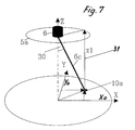
- Figure 7 explains the geometry of the object coordinates.
- An object point 10a has a coordinate (x0, y0, z0) in the object space.
- the coordinates x0 and y0 were determined on the basis of the video analysis.
- distance measurement - e.g. by simple triangulation - the effective distance z1 to Reference plane 5a of the main objective 5 can be determined.
- a part of the object 10 to be viewed Beam bundle 20 is applied by means of a beam splitter 3 via optics 2 an image sensor 1, for example the CCD of a camera, is imaged.
- the image sensor thus provides the image of the object 10 in an electronically resolved manner Form of an image sensor analysis unit (computer) 8 available.
- This Computer 8 internally sets the frequency of using suitable programs Movements (changes in image) at certain parts of the image in the form of a Histogram ( Figure 3).
- the X, Y plane of the 21 ⁇ 2-D histogram corresponds to the object coordinates X, Y.
- the z-axis of the histogram represents the frequency of movements in a certain point on the X, Y plane.
- a certain Z range of the histogram for example the maximum, calculated and the associated coordinates (x0, y0) calculated.
- the autofocus system unit 9 provides - for example a measuring beam 6c - the distance to this object point 10a (x0, y0, z0).
- the effective distance z1 between the Object point (x0, y0, z0) and the main lens 5 can be determined. Because of this determination, the main objective 5 in brought that position that the object point (x0, y0) for the viewer is shown sharply.
- the invention is not restricted to a method with a Measuring beam 6c.
- the definitive determination of the focus distance z1 at corresponding measuring point (x0, y0, z0) can also be used by other conventional Procedures are determined, e.g. Cross section, edge sharpness analysis, etc.
Landscapes
- Physics & Mathematics (AREA)
- Chemical & Material Sciences (AREA)
- Analytical Chemistry (AREA)
- General Physics & Mathematics (AREA)
- Optics & Photonics (AREA)
- Engineering & Computer Science (AREA)
- Computer Vision & Pattern Recognition (AREA)
- Microscoopes, Condenser (AREA)
- Automatic Focus Adjustment (AREA)
- Focusing (AREA)
- Studio Devices (AREA)
Abstract
Description
- der Betrachter gerade dort, wo beispielsweise mit einem Instrument gearbeitet wird, die größte Schärfe wünscht
- sich der Bildinhalt in diesem kleinen Umfeld, in welchem gearbeitet wird, infolge Bewegung des Instruments am stärksten verändert.
- In einfachen Systemen werden diese Koordinaten mit x0=y0=0 festgelegt.
- In aufwändigeren Systemen werden die zu definierenden Koordinaten (x0,y0) mittels eines Joysticks festgelegt.
- Komplexe Systeme können beispielsweise über "Eye tracking" die Koordinaten (x0,y0) eines vom Beobachterauge betrachteten Punktes ermitteln und mittels des Messsystems den Abstand dieses Punktes zum Objektiv ermitteln.
- Eine Anpassung der z0-Koordinate auf Grund der Veränderung der Helligkeit der Bildstrahlen bei Änderung der Scharfeinstellung ist aus der DE-A-1 928 432 bekannt.
- Des Weiteren geht aus der DE-A-2 053 017 die Kompensation eines Spaltbildes durch einen verstellbaren Spiegel und aus der DE-B-2 102 922 ein unsichtbares Strahlenbündel mit fotoelektrischer Einrichtung hervor.
- Sie ermöglicht eine Fokussierung auf vorgegebene (maximale) Veränderungswerte des Objektes - beispielsweise eine Bewegung chirurgischer Instrumente oder auch Vorgänge am Objekt selbst - und damit eine Fokussierung auf den Ort des Geschehens, unabhängig von der Blickrichtung der Augen des (Haupt-)Anwenders. Assistenten sehen somit immer am entscheidenden Ort scharf.
- Es sind weder eine manuelle Justierung in X-, Y-Richtung, noch in Z-Richtung notwendig.
- Es wird automatisch auf den gewünschten oder wichtigsten Betrachtungspunkt fokussiert, und zwar unabhängig von "störenden" Umgebungsbedingungen, wie Augenpupillenentfernung vom Okular, tatsächliche Blickrichtung, etc.
- Nicht nur stärkste Änderungen können erfasst werden, sondern auch vorgegebene Änderungs-Bereiche.
- Zusätzliche Reize auf die Netzhaut - z.B. Infrarot-Beleuchtung - werden vermieden.
- Das System kann auch bei "remote"-wirkenden optischen Geräten eingesetzt werden, bei denen bestimmte andere Möglichkeiten zur Autofokussierung entfallen (blickrichtungs-orientierte Systeme).
- Gelöst wird das Detektionsproblem hauptsächlich durch Software unter Ausnützung der bereits vorhandenen Rechner und Vorrichtungen (Kamera); dadurch ergibt sich eine kleinere Bauform.
- Das System kann vielseitig eingesetzt werden.
- Eine Segmentierung des Objektfeldes mit der Möglichkeit der Gewichtung der gemessenen Bewegungsaktivität und dadurch auch der Systemempfindlichkeit.
- Dies erlaubt die Auftrennung der detektierten Bewegungsaktivitäten nach Aktivitäten des Situs oder nach Aktivitäten des chirurgischen Instrumentes, z.B. eines Skalpells. Dadurch wird es beispielsweise möglich, die Fokussierung durch ein Zeigeinstrument gezielt zu steuern.
- Erlaubt einfache Detektion mit relativ geringem Rechneraufwand; erlaubt punktgenaue Detektion und daher punktorientierte z-Berechnung.
- Erlaubt ein rasches und genaues Auswerten, da alle entscheidenden Teile des Objektes relativ scharf gesehen werden und daher relativ gut auf dem Bildsensor der Kamera abgebildet werden.
- 1
- Bildsensor (CCD)
- 1a
- elektrisches Signal (Videosignal)
- 2
- Optik für Bildsensor
- 3
- Strahlenteiler
- 4
- Strahlenteilerschicht
- 5
- Objektiv
- 5a
- Referenzebene Objektiv
- 6
- Entfernungsmesser
- 6a
- Signal: zu messende Position X, Y
- 6b
- Signal: Entfernung Z am Ort X, Y
- 6c
- Messstrahl
- 7
- Fokussiereinrichtung
- 7a
- Signal: einzustellende Distanz Z
- 8
- Bildsensor-Analyseeinheit (Rechner)
- 8a
- Signal: zur Autofokus-Systemeinheit
- 9
- Autofokus-Systemeinheit
- 10
- Objekt
- 10a
- Objektpunkt / -detail
- 11
- optische Achse von (5)
- 12
- optische Achse von (1)
- 13
- Bildfeld
- 14
- bewegliches Objekt / Instrument
- 14a
- erste Position des Instruments (x1,y1)
- 14b
- zweite Position des Instruments (x2, y2)
- 15
- Histogramm
- 15a
- Histogramm des Instruments: erste Position
- 15b
- Histogramm des Instruments: zweite Position
- 20
- Strahlengang von (5)
- 21
- Strahlengang von (1)
- 22
- Strahlengang zum Betrachter
- 30
- Winkel zwischen optischer Achse / Objekttrajektorie
- 31
- Abstand zwischen Objektiv / Objekt (z1)
- X,Y,Z
- Koordinatenachsen
- z1
- Distanz
Claims (10)
- Verfahren zum Fokussieren des Objektives einer optischen Einrichtung auf ein Objekt unter Ausnützung der über einen Bildsensor gewonnenen Bildinformation vom Objekt, dadurch gekennzeichnet, dassdas Objekt (10) nach Objektfeldern (xi,yi) mit wahrnehmbaren Bildänderungen untersucht oder unterteilt wird,worauf ermittelt wird, welches der Objektfelder (x0,y0) eine bestimmte Änderungsaktivität, beispielsweise die höchste, aufweist,worauf der z1-Abstand zwischen dem Objektiv (5) und dem Objektfeld (x0,y0) mit der vorgehend bestimmten Änderungsaktivität berechnet wird,worauf dieser Wert zur rechnergestützten Ansteuerung einer Fokussiereinrichtung (7) des Objektives (5) benutzt wird.
- Verfahren nach Anspruch 1, dadurch gekennzeichnet, dass die optisch erkennbaren objektmäßigen Änderungen im Bild erfasst und nach Helligkeit sowie nach Auftreten von Reflexen gewichtet werden.
- Verfahren nach einem der vorhergehenden Ansprüche, dadurch gekennzeichnet, dass die Bildkoordinaten mit vorgegebenen Veränderungswerten - beispielsweise der häufigsten Änderung pro Zeiteinheit - bestimmt und rechnerisch gewichtet werden.
- Verfahren nach einem der vorhergehenden Ansprüche, dadurch gekennzeichnet, dass die Fokussierung auf Grund vorprogrammierter Gewichtungswerte auf die Stelle mit den entsprechenden objektmäßigen Änderungen vorgenommen wird.
- Verfahren nach einem der vorhergehenden Ansprüche, dadurch gekennzeichnet, dass das Bild zur Erkennung von optisch erkennbaren objektmäßigen Änderungen über einen Bildsensor (1) in Pixel (xi,yi) aufgelöst und der Bildsensor (1) pro Pixel ein elektrisches Signal (1a) - beispielsweise ein Videosignal - erzeugt, das für die weitere Berechnung herangezogen wird.
- Verfahren nach einem der vorhergehenden Ansprüche, dadurch gekennzeichnet, dass die Änderungen aller elektrischen Signale des Bildsensors (1) erfasst und rechnerisch in einem virtuellen 2½-D-Histogramm (15) dargestellt werden, wobei die X-, Y-Ebene des Histogrammes (15) der Ebene des Bildsensors (1) und die Z-Achse des Histogrammes (15) den Änderungen der Signale entspricht.
- Verfahren nach einem der vorhergehenden Ansprüche, dadurch gekennzeichnet, dass ein bestimmter Z-Bereich des Histogrammes (15) - beispielsweise das Maximum - festgelegt und der dazugehörige Punkt in der X-, Y-Ebene des Histogrammes (15) sowie die entsprechende Position (x0,y0) des Objektes (10) bestimmt und auf die Position (x0, y0) fokussiert wird.
- Verfahren nach einem der vorhergehenden Ansprüche, dadurch gekennzeichnet, dass das Erfassen der Änderungen bzw. Bewegungen rechnergestützt nach voreinstellbaren Parametern erfolgt und vor diesem rechnergestützten Erfassen eine manuelle Fokussierung nach herkömmlichen Gesichtspunkten durchgeführt wird.
- Vorrichtung zum Fokussieren eines optischen Systems mit einem ferngesteuerten Stellglied für ein verstellbares Objektiv, mit einem Bildsensor und einer Bildsensor-Analyseeinheit, dadurch gekennzeichnet, dass die Bildsensor-Analyseeinheit (8) einen Rechner (8) mit einem Programm umfasst, das wenigstens einen der in den vorhergehenden Ansprüchen angegebenen Verfahrensschritte durchzuführen imstande ist.
- Vorrichtung nach Anspruch 9, dadurch gekennzeichnet, dass der Rechner (8) eine Analysevorrichtung zur Bestimmung von Änderungen elektrischer Signale (1a) von Pixeln eines Bildsensors (1) umfasst.
Applications Claiming Priority (2)
| Application Number | Priority Date | Filing Date | Title |
|---|---|---|---|
| DE10106698A DE10106698A1 (de) | 2001-02-14 | 2001-02-14 | Verfahren und Vorrichtung zum automatischen Fokussieren eines optischen Gerätes |
| DE10106698 | 2001-02-14 |
Publications (3)
| Publication Number | Publication Date |
|---|---|
| EP1255146A2 true EP1255146A2 (de) | 2002-11-06 |
| EP1255146A3 EP1255146A3 (de) | 2003-11-19 |
| EP1255146B1 EP1255146B1 (de) | 2008-01-02 |
Family
ID=7673921
Family Applications (1)
| Application Number | Title | Priority Date | Filing Date |
|---|---|---|---|
| EP02100126A Expired - Lifetime EP1255146B1 (de) | 2001-02-14 | 2002-02-12 | Verfahren und Vorrichtung zum automatischen fokussieren eines optischen Gerätes |
Country Status (4)
| Country | Link |
|---|---|
| US (1) | US6884980B2 (de) |
| EP (1) | EP1255146B1 (de) |
| JP (1) | JP2002318344A (de) |
| DE (2) | DE10106698A1 (de) |
Families Citing this family (9)
| Publication number | Priority date | Publication date | Assignee | Title |
|---|---|---|---|---|
| US7196300B2 (en) * | 2003-07-18 | 2007-03-27 | Rudolph Technologies, Inc. | Dynamic focusing method and apparatus |
| TWI422896B (zh) * | 2004-07-12 | 2014-01-11 | August Technology Corp | 動態對焦方法及設備 |
| DE102005029381B4 (de) * | 2005-06-24 | 2007-04-26 | Olympus Soft Imaging Solutions Gmbh | Verfahren und Vorrichtung zur optischen Abtastung einer Probe |
| DE102011082756A1 (de) | 2011-09-15 | 2013-03-21 | Leica Microsystems (Schweiz) Ag | Autofokussierverfahren und -einrichtung für ein Mikroskop |
| US20130271575A1 (en) * | 2012-04-11 | 2013-10-17 | Zspace, Inc. | Dynamically Controlling an Imaging Microscopy System |
| US9265458B2 (en) | 2012-12-04 | 2016-02-23 | Sync-Think, Inc. | Application of smooth pursuit cognitive testing paradigms to clinical drug development |
| US9380976B2 (en) | 2013-03-11 | 2016-07-05 | Sync-Think, Inc. | Optical neuroinformatics |
| EP3396430B1 (de) * | 2017-04-27 | 2023-08-16 | Euroimmun Medizinische Labordiagnostika AG | Optische abtastanordnung und verfahren |
| CA3168826A1 (en) | 2020-01-22 | 2021-07-29 | Photonic Medical Inc. | Open view, multi-modal, calibrated digital loupe with depth sensing |
Family Cites Families (13)
| Publication number | Priority date | Publication date | Assignee | Title |
|---|---|---|---|---|
| FR1577489A (de) | 1968-06-07 | 1969-08-08 | ||
| DE2053017A1 (de) | 1970-10-29 | 1972-05-04 | Grundig Emv | Verfahren zur berührungslosen Abstandsmessung |
| DE2102922C3 (de) | 1971-01-22 | 1978-08-24 | Ernst Leitz Wetzlar Gmbh, 6330 Wetzlar | Anordnung zum selbsttätigen Fokussieren auf in optischen Geräten zu betrachtende Objekte |
| EP0366136B1 (de) * | 1988-10-27 | 1995-03-22 | Canon Kabushiki Kaisha | Bildaufnahme- und Verarbeitungseinrichtung |
| US5790710A (en) * | 1991-07-12 | 1998-08-04 | Jeffrey H. Price | Autofocus system for scanning microscopy |
| US5239170A (en) * | 1991-10-23 | 1993-08-24 | Karl Suss America, Incorporated | Autofocus method and apparatus for imaging microscopy using a predetermined visual imaging feature |
| US5483055A (en) * | 1994-01-18 | 1996-01-09 | Thompson; Timothy V. | Method and apparatus for performing an automatic focus operation for a microscope |
| US5647025A (en) * | 1994-09-20 | 1997-07-08 | Neopath, Inc. | Automatic focusing of biomedical specimens apparatus |
| DE59504515D1 (de) * | 1994-10-26 | 1999-01-21 | Leica Mikroskopie Sys Ag | Mikroskop, insbesondere operationsmikroskop |
| US6172349B1 (en) * | 1997-03-31 | 2001-01-09 | Kla-Tencor Corporation | Autofocusing apparatus and method for high resolution microscope system |
| US6974938B1 (en) * | 2000-03-08 | 2005-12-13 | Tibotec Bvba | Microscope having a stable autofocusing apparatus |
| DE10024687A1 (de) * | 2000-05-18 | 2001-11-22 | Zeiss Carl Jena Gmbh | Autofokussiereinrichtung für optische Geräte |
| US6580062B2 (en) * | 2001-05-29 | 2003-06-17 | Hewlett-Packard Development Company, L.P. | Contrast focus figure-of-merit method that is insensitive to scene illumination level |
-
2001
- 2001-02-14 DE DE10106698A patent/DE10106698A1/de not_active Withdrawn
-
2002
- 2002-02-12 DE DE50211439T patent/DE50211439D1/de not_active Expired - Lifetime
- 2002-02-12 EP EP02100126A patent/EP1255146B1/de not_active Expired - Lifetime
- 2002-02-13 US US10/073,171 patent/US6884980B2/en not_active Expired - Fee Related
- 2002-02-14 JP JP2002036735A patent/JP2002318344A/ja active Pending
Also Published As
| Publication number | Publication date |
|---|---|
| DE50211439D1 (de) | 2008-02-14 |
| EP1255146A3 (de) | 2003-11-19 |
| DE10106698A1 (de) | 2002-08-29 |
| US20020109071A1 (en) | 2002-08-15 |
| JP2002318344A (ja) | 2002-10-31 |
| US6884980B2 (en) | 2005-04-26 |
| EP1255146B1 (de) | 2008-01-02 |
Similar Documents
| Publication | Publication Date | Title |
|---|---|---|
| EP0799434B1 (de) | Mikroskop, insbesondere stereomikroskop und verfahren zum überlagern zweier bilder | |
| DE10100335B4 (de) | Vorrichtung zur Anzeige einer Größe im Blickfeld eines Benutzers und Verwendung der Vorrichtung | |
| EP0825826B1 (de) | Verfahren und vorrichtung zum parallelen erfassen von sehinformation | |
| DE102018206406B3 (de) | Mikroskopiesystem und Verfahren zum Betrieb eines Mikroskopiesystems | |
| EP0788613B2 (de) | Mikroskop, insbesondere operationsmikroskop | |
| EP0822436B1 (de) | Verfahren zur Ermittlung von Positionsdaten und Vorrichtung für das Messen der Vergrösserung in einem optischen Strahlengang | |
| EP2672915A1 (de) | Endoskopisches bildverarbeitungssystem mit mitteln, welche im erfassungsbereich einer optischen digitalkamera eine geometrische vermessungsinformation erzeugen | |
| DE4134481A1 (de) | Operationsmikroskop zur rechnergestuetzten, stereotaktischen mikrochirurgie, sowie verfahren zu dessen betrieb | |
| DE102017108371B4 (de) | Medizinisch-optisches Darstellungssystem und Verfahren zum Betreiben desselben | |
| DE102015117824B4 (de) | Vorrichtung und Verfahren zum Einstellen eines Fokusabstands in einem optischen Beobachtungsgerät | |
| DE102014007909A1 (de) | Chirurgisches Mikroskop | |
| DE102020106535A1 (de) | Verfahren zum Anpassen einer Bildmaske | |
| EP1255146B1 (de) | Verfahren und Vorrichtung zum automatischen fokussieren eines optischen Gerätes | |
| DE10315592B4 (de) | Verfahren zum Ausführen von Interaktionen an sich räumlich und zeitlich verändernden mikroskopischen Objekten und System hierzu | |
| EP1262810A2 (de) | Verfahren zur Entfernungsmessung ausgedehnter Objekte in Verbindung mit einer optischen Betrachtungseinrichtung und Mikroskop zur Durchführung desselben | |
| DE10225077B4 (de) | Objektverfolgeanordnung für medizinische Operationen | |
| EP3554063A1 (de) | Digitaler sucher | |
| DE102021207950A1 (de) | Verfahren und System zur Bestimmung einer Lage zumindest eines Objekts in einem Operationssaal | |
| DE102023205631B4 (de) | Betrieb eines Koordinatenmessgeräts mit personengeführtem Sensor | |
| DE102009042712B4 (de) | Wiedergabesystem und Verfahren zum Wiedergeben einer Operations-Umgebung | |
| DE102024126167A1 (de) | Gelenkmikroskop, medizinisches Instrument und Verfahren zum Betrieb eines Gelenkmikroskops | |
| DE102024209531A1 (de) | Verfahren zur Steuerung eines medizinischen Visualisierungssystems und medizinisches Visualisierungssystem | |
| DE102024123657A1 (de) | Vorrichtung und Verfahren zum Erzeugen eines Steuersignals für ein medizinisches Instrument oder eine medizinische Bildgebungseinrichtung | |
| DE102024131547A1 (de) | Verfahren zur Erzeugung eines augmentierten Abbilds durch ein medizinisches Visualisierungssystem und medizinisches Visualisierungssystem | |
| WO2025224161A1 (de) | Verfahren zur bereitstellung von verschiedenen stereo-bildausgabesignalen durch ein medizinisches visualisierungssystem, medizinisches visualisierungssystem und computerprogrammprodukt |
Legal Events
| Date | Code | Title | Description |
|---|---|---|---|
| PUAI | Public reference made under article 153(3) epc to a published international application that has entered the european phase |
Free format text: ORIGINAL CODE: 0009012 |
|
| AK | Designated contracting states |
Kind code of ref document: A2 Designated state(s): AT BE CH CY DE DK ES FI FR GB GR IE IT LI LU MC NL PT SE TR |
|
| AX | Request for extension of the european patent |
Free format text: AL;LT;LV;MK;RO;SI |
|
| PUAL | Search report despatched |
Free format text: ORIGINAL CODE: 0009013 |
|
| AK | Designated contracting states |
Kind code of ref document: A3 Designated state(s): AT BE CH CY DE DK ES FI FR GB GR IE IT LI LU MC NL PT SE TR |
|
| AX | Request for extension of the european patent |
Extension state: AL LT LV MK RO SI |
|
| RIC1 | Information provided on ipc code assigned before grant |
Ipc: 7H 04N 5/232 B Ipc: 7G 02B 21/24 B Ipc: 7G 06T 7/20 B Ipc: 7G 02B 21/22 A |
|
| 17P | Request for examination filed |
Effective date: 20040422 |
|
| RAP1 | Party data changed (applicant data changed or rights of an application transferred) |
Owner name: LEICA MICROSYSTEMS (SCHWEIZ) AG |
|
| AKX | Designation fees paid |
Designated state(s): CH DE FR GB LI |
|
| 17Q | First examination report despatched |
Effective date: 20040716 |
|
| GRAP | Despatch of communication of intention to grant a patent |
Free format text: ORIGINAL CODE: EPIDOSNIGR1 |
|
| GRAS | Grant fee paid |
Free format text: ORIGINAL CODE: EPIDOSNIGR3 |
|
| GRAA | (expected) grant |
Free format text: ORIGINAL CODE: 0009210 |
|
| AK | Designated contracting states |
Kind code of ref document: B1 Designated state(s): CH DE FR GB LI |
|
| REG | Reference to a national code |
Ref country code: GB Ref legal event code: FG4D Free format text: NOT ENGLISH |
|
| REG | Reference to a national code |
Ref country code: CH Ref legal event code: EP |
|
| REF | Corresponds to: |
Ref document number: 50211439 Country of ref document: DE Date of ref document: 20080214 Kind code of ref document: P |
|
| GBV | Gb: ep patent (uk) treated as always having been void in accordance with gb section 77(7)/1977 [no translation filed] | ||
| REG | Reference to a national code |
Ref country code: CH Ref legal event code: PL |
|
| EN | Fr: translation not filed | ||
| PG25 | Lapsed in a contracting state [announced via postgrant information from national office to epo] |
Ref country code: CH Free format text: LAPSE BECAUSE OF NON-PAYMENT OF DUE FEES Effective date: 20080229 Ref country code: LI Free format text: LAPSE BECAUSE OF NON-PAYMENT OF DUE FEES Effective date: 20080229 |
|
| PLBE | No opposition filed within time limit |
Free format text: ORIGINAL CODE: 0009261 |
|
| STAA | Information on the status of an ep patent application or granted ep patent |
Free format text: STATUS: NO OPPOSITION FILED WITHIN TIME LIMIT |
|
| 26N | No opposition filed |
Effective date: 20081003 |
|
| PG25 | Lapsed in a contracting state [announced via postgrant information from national office to epo] |
Ref country code: GB Free format text: LAPSE BECAUSE OF FAILURE TO SUBMIT A TRANSLATION OF THE DESCRIPTION OR TO PAY THE FEE WITHIN THE PRESCRIBED TIME-LIMIT Effective date: 20080102 |
|
| PG25 | Lapsed in a contracting state [announced via postgrant information from national office to epo] |
Ref country code: FR Free format text: LAPSE BECAUSE OF FAILURE TO SUBMIT A TRANSLATION OF THE DESCRIPTION OR TO PAY THE FEE WITHIN THE PRESCRIBED TIME-LIMIT Effective date: 20081024 |
|
| PGFP | Annual fee paid to national office [announced via postgrant information from national office to epo] |
Ref country code: DE Payment date: 20150219 Year of fee payment: 14 |
|
| REG | Reference to a national code |
Ref country code: DE Ref legal event code: R119 Ref document number: 50211439 Country of ref document: DE |
|
| PG25 | Lapsed in a contracting state [announced via postgrant information from national office to epo] |
Ref country code: DE Free format text: LAPSE BECAUSE OF NON-PAYMENT OF DUE FEES Effective date: 20160901 |