EP1255171A2 - Dispositif de chargement et de déchargement pour des supports d'impression dans des imprimantes ou des photocopieuses - Google Patents
Dispositif de chargement et de déchargement pour des supports d'impression dans des imprimantes ou des photocopieuses Download PDFInfo
- Publication number
- EP1255171A2 EP1255171A2 EP02008220A EP02008220A EP1255171A2 EP 1255171 A2 EP1255171 A2 EP 1255171A2 EP 02008220 A EP02008220 A EP 02008220A EP 02008220 A EP02008220 A EP 02008220A EP 1255171 A2 EP1255171 A2 EP 1255171A2
- Authority
- EP
- European Patent Office
- Prior art keywords
- webs
- guide device
- corona
- corona wire
- unloading
- Prior art date
- Legal status (The legal status is an assumption and is not a legal conclusion. Google has not performed a legal analysis and makes no representation as to the accuracy of the status listed.)
- Granted
Links
Images



Classifications
-
- G—PHYSICS
- G03—PHOTOGRAPHY; CINEMATOGRAPHY; ANALOGOUS TECHNIQUES USING WAVES OTHER THAN OPTICAL WAVES; ELECTROGRAPHY; HOLOGRAPHY
- G03G—ELECTROGRAPHY; ELECTROPHOTOGRAPHY; MAGNETOGRAPHY
- G03G15/00—Apparatus for electrographic processes using a charge pattern
- G03G15/02—Apparatus for electrographic processes using a charge pattern for laying down a uniform charge, e.g. for sensitising; Corona discharge devices
- G03G15/0291—Apparatus for electrographic processes using a charge pattern for laying down a uniform charge, e.g. for sensitising; Corona discharge devices corona discharge devices, e.g. wires, pointed electrodes, means for cleaning the corona discharge device
-
- G—PHYSICS
- G03—PHOTOGRAPHY; CINEMATOGRAPHY; ANALOGOUS TECHNIQUES USING WAVES OTHER THAN OPTICAL WAVES; ELECTROGRAPHY; HOLOGRAPHY
- G03G—ELECTROGRAPHY; ELECTROPHOTOGRAPHY; MAGNETOGRAPHY
- G03G2215/00—Apparatus for electrophotographic processes
- G03G2215/00362—Apparatus for electrophotographic processes relating to the copy medium handling
- G03G2215/00535—Stable handling of copy medium
- G03G2215/00654—Charging device
Definitions
- the invention relates to a device for unloading or charging of print media in Printing or copying machines, in particular of print media as they pass through the Transport lines of printing or copying machines, according to the preamble of Claim 1.
- Print media such as sheets of paper, foils or the like are passed through the Transport lanes of printing and copying machines are electrically charged. In order to prevent printed sheets of paper or foils from jamming together in the output tray must adhere to sufficient electrically conductive components of the transport track these electrical charges are removed.
- Such unloading devices are known from US 5,890,046, wherein a High voltage alternating field between two corona discharge devices with each a corona wire is applied and the print medium between these corona discharge devices is passed through.
- a High voltage alternating field between two corona discharge devices with each a corona wire is applied and the print medium between these corona discharge devices is passed through.
- a guiding device is combined within a Corona loading / unloading devices are shown, which has webs that cover the interior of the Bridge the unloading device.
- the webs are in the middle of the Guide device further apart than in the outer areas arranged.
- the webs have different inclinations with respect to Direction of transport of a printing material on the unloading device.
- corona loading / unloading devices One problem with such corona loading / unloading devices is changing the electric field between two corona discharge devices, if between the Corona wires a print carrier, or no print carrier is located. Is also one Depending on the electrical resistance of such a pressure medium. In the edge area of the gap between the corona wires, in which the passage gap is no longer covered by the print carrier, it can be due to the significant difference the electrical resistance and the associated greater field strength outside arcing in the area covered by the print medium. such Flashovers generate noise that is disruptive to the control system and result in unfavorable case to damage the electronics.
- the device according to the invention extend the narrow webs of the guide device at an angle ⁇ to Direction of transport of the print media over the entire width of the passage gap.
- the width of the passage gap advantageously corresponds essentially to the width B. of the largest print carrier format, which is unloaded by means of the corona unloading device.
- the webs and possibly the frame of the guide device consist of one electrically non-conductive material. This will influence the guide device minimizes the electric field between the corona wires. This supports the lean Design of the webs that bridge the passage gap and thereby one if possible cover the small area of the passage gap and thus also to the smallest possible Distortion of the electric field between the corona wires.
- the device is advantageously in two parts on both sides of the transport path a printing material with at least a first corona wire and a first Guide device on a first side and at least a second corona wire and a second guide device on a second side.
- the webs of the guide device at the edge of the passage gap a smaller distance to each other than the webs in the middle of the passage gap.
- the edge is drawn of the guide gap in that the outer edges for all print formats to be guided the print medium is within the marginal area. Because of the smaller distance between the webs it is achieved that in the central area only a slight coverage of the Through gap is caused, material is saved and on the other hand in the edge area it is guaranteed with great certainty that, for example, dog ears that the Can have pressure carriers, through the closer positioned webs from the Pass gap be safely guided into the transport path.
- the webs are the Guide device at the edge of the passage gap at a larger angle against the Transport direction of the print carrier inclined than in the middle of the passage gap.
- the guiding function of the webs can advantageously be supported.
- the edge area of the guide device should mainly be bent or bent Guide corners securely over the passage gap.
- This functionality takes away increasing angle to the transport direction up to a position of the webs of 45 ° to Direction of transport too.
- this function improves with a smaller angle of the webs to the direction of transport, as a result of which Probability that an incoming leading edge jams with a web, is reduced. It is therefore advantageous if the inclination of the webs to the direction of transport increases from the inside out.
- the webs on the edge of the Pass gap an angle of essentially 45 ° to the transport direction of the Print carrier on.
- the webs in the In the middle of the passage gap an angle of essentially 15 ° to the transport direction of the print carrier.
- the webs between the middle and the particularly advantageously point Edge of the passage gap an angle between essentially 15 ° to 45 ° to Direction of transport of the print carrier, with the angle increasing outwards.
- the guide device is advantageously designed such that the webs on the the side facing the print carrier are rounded. This will be the leadership role the device supports, since the bearing surface of a print carrier for Guide device is reduced. It also avoids edges that otherwise always represent possibilities for tilting a print medium in the transport path.
- the guide device has inlet bevels which point in the direction of the Normals of the print carrier are bevelled against the direction of transport and one Direct the incoming print medium towards the center of the passage gap.
- inlet bevels which point in the direction of the Normals of the print carrier are bevelled against the direction of transport and one Direct the incoming print medium towards the center of the passage gap.
- the Guide device one tongue in the middle of the narrow side of the guide device on the side facing away from the print carrier.
- the tongues cover in the edge area of the Through gap the corona wires against each other. This is the straight path from one corona wire to the other for the corona ions in the edge area of the Pass gap interrupted.
- the ion current increases in the edge area, which increases the risk from arcing over there.
- the tongues are in this area however, especially in the direct connection line between two corona wires Corona ions are largely trapped and therefore do not contribute to another Ionization of the air in the edge area of the passage gap. This eliminates the risk of Arcing is reduced.
- the removal of the ends of the tongues to each other and thus the length of the tongues to the format of the smallest processing printing medium adapted, in particular in such a way that the smallest too processing print carrier, which runs through the center of the guide device, at least covers the ends of both tongues.
- Each tongue of a guide device according to the invention advantageously has one Inlet bevel on that in the direction of the normal of the print medium against the Transport direction is chamfered. This enables the management function of device according to the invention are further supported.
- the guide device has the side facing away from the print carrier devices by means of which they on the Unloading device can be attached. This can reduce the assembly effort and the use of other fasteners can be dispensed with.
- the guide devices proposed according to the invention for guiding Print media can be used in all sheet-processing machines and their components use that are equipped with an unloading device or charging device. Furthermore, a range of applications is opened for all devices that process print media. in which print media are guided along a transport path.
- FIGS. 1 to 7 relates to a preferred one Embodiment of the inventive device in connection with a Unloading.
- the content of this description is easy to understand Charger transferable.
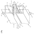
- FIG. 1 and 2 schematically show the overall structure of a corona discharge device 2, 3 only for the purpose of simplifying the description components essential to the invention are illustrated or explained. More, general known and necessary for operating the device drive means or electrical Circuits are only shown schematically or are only in general form described.
- the corona discharge device 2, 3 essentially consists of a corona wire 5, 5 ', which is tensioned in a housing 8, 8' and with a high voltage source 4, 4 ' connected is.
- the corona unloading device 2 is located as in FIG. 1 shown a counter electrode 6, which is typically grounded.
- When creating High voltage on the corona wire 5 creates an electrical field between the corona wire 5 and counter electrode 6.
- a sufficiently large electrical voltage typically between 3 to 20 kVpp
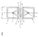
- air ions are in the close range around the Corona wire accelerates through the prevailing field and generate more Ions, so-called corona ions, which are located along the field lines 20 (see FIG. 7) Move towards the counter electrode.
- the guide device 1 is between the actual corona discharge device 2, 3 and the pressure carrier 7 on the corresponding corona unloading device 2, 3 attached.
- the lugs shown in FIGS. 4 and 6 serve for this purpose 19, which are inserted into the housing 8 of the respective unloading device 2, 3 can. It goes without saying to the specialist working in this field that everyone other mechanisms known from the prior art and / or Active connections for detachable or non-detachable fastening of a plastic part with another object, namely the guide device 1 with the frame of the Unloading device 8 can be used.
- a guide device 1 is shown in plan view.
- the Transport direction 10 indicates the direction in which the print carrier 7 to be unloaded Unloading device 2, 3 pass.
- the guide device 1 can be moved along the width B of the guide device 1 in Divide essentially into three areas, two edge areas 14, 14 'and one Middle region 15.
- the middle region 15 is characterized in that it is made by everyone central pressure carrier 7 always within the inherent tolerances of a Transport device is completely covered by a pressure carrier 7.
- the outer edges of the print carriers 7 run in the edge regions Print carrier 7 further inside or outside.
- the total width B of the passage gap 9 is that Upper limit for the formats of print media 7 that can be used by means of the Unloading device 2, 3 can be unloaded.
- Within the edge areas 14, 14 ' have the webs 11 a smaller distance from each other than the webs 12, 13 in Middle section 15.
- each guide device there are 16 webs 11, 12, 13 on each guide device 1.
- the eight webs 11, which bridge the passage gap of the unloading device, have a larger angle ⁇ 1 to the transport direction 10 in the edge region 14, 14 ' than the angles ⁇ 2 , ⁇ 3 of the eight webs 12, 13 in the central region 15 of the guide device 1.
- the angle ⁇ 2 , ⁇ 3 of the webs 12, 13 decreases further towards the transport direction 10 towards the center.
- the webs 12, 13 In the central region, the webs 12, 13 always assume the values of 30 ° and 15 ° for the angle ⁇ 2 , ⁇ 3 between the webs 12, 13 and the transport direction 10 in pairs from outside to inside.
- the inventive device can also be equipped with one of 16 different numbers of webs and the angle values of the angles ⁇ 1 , ⁇ 2 , ⁇ 3 vary from those in this embodiment within the scope of the claims can.
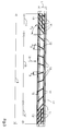
- FIG. 4 shows a semi-oblique side view of the guide device 1.
- the leading effect that the guide device 1 has is supported by an inlet slope 16 or outlet slope 17, which respectively enlarge the inlet and outlet area of the passage gap and have an opening angle ⁇ 1 or ⁇ 2 between the transport direction 10, so that the Leading edge of an incoming print carrier 7 is directed into the actual passage gap 9, as shown in Fig. 5.
- the webs 11, 12, 13 on the the side facing the print carrier 7 rounded or with a chamfer 11a (see FIG. 4) provided so that the front of a continuous print carrier 7 canting possible unevenness of the webs 11, 12, 13 is avoided.
- the Tongues 18, 18 ' have an inlet slope 16 or outlet slope 17 comparable chamfer 18a on the side closer to the incoming print carrier 7.
- the tongues 18, 18 ' are instead of a chamfer 18a round off.
- the ion current starts from the direct one Connection line 21 between the two corona wires 5, 5 'along the length L of the Pass gap 9 from, the strongest discharge of a pressure carrier 7 but also the largest Ionization of the air in the absence of a pressure carrier 7 takes place on the direct Connection line 21 instead.
- this large ion current is not desirable because it is caused by the associated considerable ionization of the air to spark flashes between the Corona wires 5, 5 'can come. This is avoided by the tongues 18, 18 ' the ion current on the direct connecting line 21 between the corona wires 5, 5 ' suppress and thereby the ionization of the air in the passage gap 9 significantly to reduce.
- the guide device described is injection molded from plastic. It should be noted that the guide device 1 is a first one Unloading device 2 and the guide device 1 of a second unloading device 3 is a structurally identical device, which means a considerable manufacturing effort can be avoided.
Landscapes
- Physics & Mathematics (AREA)
- Engineering & Computer Science (AREA)
- Plasma & Fusion (AREA)
- General Physics & Mathematics (AREA)
- Feeding Of Articles By Means Other Than Belts Or Rollers (AREA)
- Electrostatic Charge, Transfer And Separation In Electrography (AREA)
- Sheets, Magazines, And Separation Thereof (AREA)
Applications Claiming Priority (2)
| Application Number | Priority Date | Filing Date | Title |
|---|---|---|---|
| DE10121289 | 2001-05-02 | ||
| DE10121289A DE10121289A1 (de) | 2001-05-02 | 2001-05-02 | Vorrichtung zum Führen von Druckträgern durch eine Entladevorrichtung |
Publications (3)
| Publication Number | Publication Date |
|---|---|
| EP1255171A2 true EP1255171A2 (fr) | 2002-11-06 |
| EP1255171A3 EP1255171A3 (fr) | 2006-03-08 |
| EP1255171B1 EP1255171B1 (fr) | 2009-08-05 |
Family
ID=7683346
Family Applications (1)
| Application Number | Title | Priority Date | Filing Date |
|---|---|---|---|
| EP02008220A Expired - Lifetime EP1255171B1 (fr) | 2001-05-02 | 2002-04-18 | Dispositif de chargement et de déchargement pour des supports d'impression dans des imprimantes ou des photocopieuses |
Country Status (4)
| Country | Link |
|---|---|
| US (1) | US6668154B2 (fr) |
| EP (1) | EP1255171B1 (fr) |
| AT (1) | ATE438888T1 (fr) |
| DE (2) | DE10121289A1 (fr) |
Families Citing this family (8)
| Publication number | Priority date | Publication date | Assignee | Title |
|---|---|---|---|---|
| US6965749B2 (en) * | 2004-02-02 | 2005-11-15 | Lite-On Technology Corporation | Image inputting device with electrostatic generating device |
| JP5414414B2 (ja) * | 2009-08-05 | 2014-02-12 | キヤノン株式会社 | 画像形成装置 |
| US8727488B2 (en) * | 2010-03-04 | 2014-05-20 | Hewlett-Packard Development Company, L.P. | Apparatus for capturing aerosols |
| JP6271947B2 (ja) * | 2013-10-29 | 2018-01-31 | キヤノン株式会社 | 給電装置、画像形成装置、及び給電装置の製造方法 |
| JP7409098B2 (ja) * | 2020-01-10 | 2024-01-09 | 富士フイルムビジネスイノベーション株式会社 | 除電装置及びこれを用いた媒体処理装置 |
| JP2024107617A (ja) * | 2023-01-30 | 2024-08-09 | キヤノン株式会社 | 除電装置及び画像形成システム |
| JP2024107503A (ja) * | 2023-01-30 | 2024-08-09 | キヤノン株式会社 | 除電装置及び画像形成装置 |
| JP2024107672A (ja) * | 2023-01-30 | 2024-08-09 | キヤノン株式会社 | 除電装置及び画像形成システム |
Family Cites Families (24)
| Publication number | Priority date | Publication date | Assignee | Title |
|---|---|---|---|---|
| BE545664A (fr) * | 1955-03-03 | |||
| US3620617A (en) * | 1969-11-24 | 1971-11-16 | Ibm | Electrophotographic apparatus with improved toner transfer |
| US3722992A (en) * | 1971-01-11 | 1973-03-27 | Pitney Bowes Inc | Apparatus for creating an electrostatic latent image by charge modulation |
| US4130852A (en) * | 1977-07-29 | 1978-12-19 | Eastman Kodak Company | Grounded grid static discharge apparatus |
| JPS58207065A (ja) * | 1982-05-27 | 1983-12-02 | Canon Inc | 転写装置 |
| JPS5952268A (ja) * | 1982-09-20 | 1984-03-26 | Konishiroku Photo Ind Co Ltd | 転写紙分離方法 |
| JPS6026062U (ja) | 1983-07-28 | 1985-02-22 | 株式会社リコー | 画像形成装置 |
| JPS6250781A (ja) * | 1985-08-29 | 1987-03-05 | Sharp Corp | 転写剥離装置 |
| US4801975A (en) * | 1986-04-18 | 1989-01-31 | Mita Industrial Co. Ltd. | Eraser lamp and transparent guide plate in electrostatic image transfer |
| JP2536550B2 (ja) | 1987-10-16 | 1996-09-18 | ミノルタ株式会社 | 静電複写機の除電分離装置 |
| JPH0617127Y2 (ja) * | 1987-11-25 | 1994-05-02 | 三田工業株式会社 | コロナ放電器 |
| JPH0252380A (ja) * | 1988-08-17 | 1990-02-21 | Canon Inc | 画像形成装置の転写分離帯電器 |
| US5130752A (en) * | 1989-05-24 | 1992-07-14 | Mita Industrial Co., Ltd. | Transfer device with a ribbed guiding member |
| US5132199A (en) * | 1989-07-31 | 1992-07-21 | Mita Industrial Co., Ltd. | Electrophotographic image-forming method |
| EP0473161B1 (fr) * | 1990-08-31 | 1995-08-09 | Sharp Kabushiki Kaisha | Dispositif de séparation de papier d'enregistrement |
| JPH04186258A (ja) * | 1990-11-20 | 1992-07-03 | Matsushita Electric Ind Co Ltd | スコロトロン帯電装置 |
| DE4305686C2 (de) | 1992-02-24 | 1999-07-15 | Fujitsu Ltd | Tonerbild-Übertragungsvorrichtung einschließlich einer Übertragungsladevorrichtung und einer Wechselspannungs-Ladungslöschvorrichtung |
| JPH0611979A (ja) * | 1992-06-29 | 1994-01-21 | Fujitsu Ltd | 転写ユニット |
| US5552873A (en) * | 1993-02-09 | 1996-09-03 | Fujitsu Limited | Electrophotographic image forming apparatus having a pre-transfer pressing roller |
| JP3221255B2 (ja) * | 1994-10-19 | 2001-10-22 | 富士ゼロックス株式会社 | 画像形成装置 |
| JP3187677B2 (ja) * | 1995-03-03 | 2001-07-11 | 京セラミタ株式会社 | 画像形成装置の転写分離部構造 |
| JPH08262837A (ja) * | 1995-03-22 | 1996-10-11 | Mita Ind Co Ltd | 画像形成装置のコロナ放電器 |
| US5596783A (en) * | 1995-06-07 | 1997-01-28 | Electrostatics, Inc. | Sheet and web cleaner with face plate on suction hood |
| JP3671617B2 (ja) * | 1997-09-01 | 2005-07-13 | コニカミノルタホールディングス株式会社 | 画像形成装置 |
-
2001
- 2001-05-02 DE DE10121289A patent/DE10121289A1/de not_active Withdrawn
-
2002
- 2002-04-18 DE DE50213734T patent/DE50213734D1/de not_active Expired - Lifetime
- 2002-04-18 AT AT02008220T patent/ATE438888T1/de not_active IP Right Cessation
- 2002-04-18 EP EP02008220A patent/EP1255171B1/fr not_active Expired - Lifetime
- 2002-04-19 US US10/126,490 patent/US6668154B2/en not_active Expired - Lifetime
Also Published As
| Publication number | Publication date |
|---|---|
| US20020186990A1 (en) | 2002-12-12 |
| DE50213734D1 (de) | 2009-09-17 |
| EP1255171B1 (fr) | 2009-08-05 |
| ATE438888T1 (de) | 2009-08-15 |
| EP1255171A3 (fr) | 2006-03-08 |
| DE10121289A1 (de) | 2002-11-07 |
| US6668154B2 (en) | 2003-12-23 |
Similar Documents
| Publication | Publication Date | Title |
|---|---|---|
| DE19503110B4 (de) | Bogenleiteinrichtung für Druckmaschinen | |
| EP0115611B1 (fr) | Dispositif à imprimer avec un champ électrostatique auxiliaire | |
| EP1255171B1 (fr) | Dispositif de chargement et de déchargement pour des supports d'impression dans des imprimantes ou des photocopieuses | |
| DE69032610T2 (de) | Bilderzeugungsgerät | |
| EP0934224B1 (fr) | Inverseur de marche pour article en forme de feuille | |
| EP1679187A2 (fr) | Dispositif de guidage de feuilles avec un bord en forme de peigne isolé électriquement | |
| EP0532881A2 (fr) | Dispositif pour la connexion électrique de rails conducteurs disposés parallelement | |
| EP1155834A2 (fr) | Dispositif pour enlever des charges électriques d'un matériau plan | |
| DE69019575T2 (de) | Vorrichtung zum Aufnehmen von Bögen von der Unterseite eines Stapels. | |
| DE102007055661B4 (de) | Vorrichtung zum Trocknen eines Druckmediums | |
| DE202017107148U1 (de) | Abscheidevorrichtung | |
| EP0507306B1 (fr) | Système de transport par courroie | |
| EP1450216B1 (fr) | Dispositif de corotron avec une unité d'alimentation électrique | |
| EP1088780A2 (fr) | Dispositif pour fermer sélectivement des orifice de soufflage dans dispositifs de guidage ou barres pour le support à imprimer dans machines d'impression rotatives | |
| EP0806389A2 (fr) | Dispositif pour transporter un courant de feuilles se chevauchant | |
| DE102011112361A1 (de) | Vorrichtung zum Verblocken eines stehenden Stapels flacher Druckerzeugnisse | |
| EP0774351B1 (fr) | Appareil pour fixer électrostatiquement un produit plat multi-couche | |
| DE19755745C2 (de) | Einrichtung zum elektrostatischen Beeinflussen von Signaturen | |
| DE3430091C2 (fr) | ||
| DE69718701T2 (de) | Blattübergabesystem | |
| EP0637897A2 (fr) | Dispositif pour le chauffage inductif par champ longitudinal de pièces métalliques planes | |
| EP0860799B1 (fr) | Dispositif de protection pour une machine à affranchir | |
| EP0091065B1 (fr) | Dispositif de transport séparé dans un bain d'un appareil de développement par diffusion de deux feuilles pourvues de couches photosensibles | |
| DE602004010322T2 (de) | Vorrichtung zur Erdung eines Druckfilms | |
| DE102009009856A1 (de) | Überführband zum Überführen einer Papier- oder Kartonbahn und Vorrichtung zum Überführen einer Papier- oder Kartonbahn |
Legal Events
| Date | Code | Title | Description |
|---|---|---|---|
| PUAI | Public reference made under article 153(3) epc to a published international application that has entered the european phase |
Free format text: ORIGINAL CODE: 0009012 |
|
| AK | Designated contracting states |
Kind code of ref document: A2 Designated state(s): AT BE CH CY DE DK ES FI FR GB GR IE IT LI LU MC NL PT SE TR |
|
| AX | Request for extension of the european patent |
Free format text: AL;LT;LV;MK;RO;SI |
|
| RAP1 | Party data changed (applicant data changed or rights of an application transferred) |
Owner name: EASTMAN KODAK COMPANY |
|
| PUAL | Search report despatched |
Free format text: ORIGINAL CODE: 0009013 |
|
| AK | Designated contracting states |
Kind code of ref document: A3 Designated state(s): AT BE CH CY DE DK ES FI FR GB GR IE IT LI LU MC NL PT SE TR |
|
| AX | Request for extension of the european patent |
Extension state: AL LT LV MK RO SI |
|
| 17P | Request for examination filed |
Effective date: 20060325 |
|
| AKX | Designation fees paid |
Designated state(s): AT BE CH CY DE DK ES FI FR GB GR IE IT LI LU MC NL PT SE TR |
|
| 17Q | First examination report despatched |
Effective date: 20061207 |
|
| GRAP | Despatch of communication of intention to grant a patent |
Free format text: ORIGINAL CODE: EPIDOSNIGR1 |
|
| GRAS | Grant fee paid |
Free format text: ORIGINAL CODE: EPIDOSNIGR3 |
|
| GRAA | (expected) grant |
Free format text: ORIGINAL CODE: 0009210 |
|
| AK | Designated contracting states |
Kind code of ref document: B1 Designated state(s): AT BE CH CY DE DK ES FI FR GB GR IE IT LI LU MC NL PT SE TR |
|
| REG | Reference to a national code |
Ref country code: GB Ref legal event code: FG4D Free format text: NOT ENGLISH |
|
| REG | Reference to a national code |
Ref country code: CH Ref legal event code: EP |
|
| REG | Reference to a national code |
Ref country code: IE Ref legal event code: FG4D |
|
| REF | Corresponds to: |
Ref document number: 50213734 Country of ref document: DE Date of ref document: 20090917 Kind code of ref document: P |
|
| PG25 | Lapsed in a contracting state [announced via postgrant information from national office to epo] |
Ref country code: SE Free format text: LAPSE BECAUSE OF FAILURE TO SUBMIT A TRANSLATION OF THE DESCRIPTION OR TO PAY THE FEE WITHIN THE PRESCRIBED TIME-LIMIT Effective date: 20090805 Ref country code: FI Free format text: LAPSE BECAUSE OF FAILURE TO SUBMIT A TRANSLATION OF THE DESCRIPTION OR TO PAY THE FEE WITHIN THE PRESCRIBED TIME-LIMIT Effective date: 20090805 Ref country code: ES Free format text: LAPSE BECAUSE OF FAILURE TO SUBMIT A TRANSLATION OF THE DESCRIPTION OR TO PAY THE FEE WITHIN THE PRESCRIBED TIME-LIMIT Effective date: 20091116 |
|
| NLV1 | Nl: lapsed or annulled due to failure to fulfill the requirements of art. 29p and 29m of the patents act | ||
| PG25 | Lapsed in a contracting state [announced via postgrant information from national office to epo] |
Ref country code: NL Free format text: LAPSE BECAUSE OF FAILURE TO SUBMIT A TRANSLATION OF THE DESCRIPTION OR TO PAY THE FEE WITHIN THE PRESCRIBED TIME-LIMIT Effective date: 20090805 |
|
| REG | Reference to a national code |
Ref country code: IE Ref legal event code: FD4D |
|
| PG25 | Lapsed in a contracting state [announced via postgrant information from national office to epo] |
Ref country code: PT Free format text: LAPSE BECAUSE OF FAILURE TO SUBMIT A TRANSLATION OF THE DESCRIPTION OR TO PAY THE FEE WITHIN THE PRESCRIBED TIME-LIMIT Effective date: 20091205 |
|
| PG25 | Lapsed in a contracting state [announced via postgrant information from national office to epo] |
Ref country code: IE Free format text: LAPSE BECAUSE OF FAILURE TO SUBMIT A TRANSLATION OF THE DESCRIPTION OR TO PAY THE FEE WITHIN THE PRESCRIBED TIME-LIMIT Effective date: 20090805 Ref country code: DK Free format text: LAPSE BECAUSE OF FAILURE TO SUBMIT A TRANSLATION OF THE DESCRIPTION OR TO PAY THE FEE WITHIN THE PRESCRIBED TIME-LIMIT Effective date: 20090805 |
|
| PLBE | No opposition filed within time limit |
Free format text: ORIGINAL CODE: 0009261 |
|
| STAA | Information on the status of an ep patent application or granted ep patent |
Free format text: STATUS: NO OPPOSITION FILED WITHIN TIME LIMIT |
|
| PGFP | Annual fee paid to national office [announced via postgrant information from national office to epo] |
Ref country code: BE Payment date: 20091123 Year of fee payment: 9 |
|
| 26N | No opposition filed |
Effective date: 20100507 |
|
| PG25 | Lapsed in a contracting state [announced via postgrant information from national office to epo] |
Ref country code: GR Free format text: LAPSE BECAUSE OF FAILURE TO SUBMIT A TRANSLATION OF THE DESCRIPTION OR TO PAY THE FEE WITHIN THE PRESCRIBED TIME-LIMIT Effective date: 20091106 |
|
| BERE | Be: lapsed |
Owner name: EASTMAN KODAK CY Effective date: 20100430 |
|
| PG25 | Lapsed in a contracting state [announced via postgrant information from national office to epo] |
Ref country code: MC Free format text: LAPSE BECAUSE OF NON-PAYMENT OF DUE FEES Effective date: 20100430 |
|
| REG | Reference to a national code |
Ref country code: CH Ref legal event code: PL |
|
| REG | Reference to a national code |
Ref country code: FR Ref legal event code: ST Effective date: 20101230 |
|
| PG25 | Lapsed in a contracting state [announced via postgrant information from national office to epo] |
Ref country code: CH Free format text: LAPSE BECAUSE OF NON-PAYMENT OF DUE FEES Effective date: 20100430 Ref country code: LI Free format text: LAPSE BECAUSE OF NON-PAYMENT OF DUE FEES Effective date: 20100430 |
|
| PG25 | Lapsed in a contracting state [announced via postgrant information from national office to epo] |
Ref country code: IT Free format text: LAPSE BECAUSE OF FAILURE TO SUBMIT A TRANSLATION OF THE DESCRIPTION OR TO PAY THE FEE WITHIN THE PRESCRIBED TIME-LIMIT Effective date: 20090805 Ref country code: BE Free format text: LAPSE BECAUSE OF NON-PAYMENT OF DUE FEES Effective date: 20100430 |
|
| PG25 | Lapsed in a contracting state [announced via postgrant information from national office to epo] |
Ref country code: AT Free format text: LAPSE BECAUSE OF NON-PAYMENT OF DUE FEES Effective date: 20100418 |
|
| PG25 | Lapsed in a contracting state [announced via postgrant information from national office to epo] |
Ref country code: FR Free format text: LAPSE BECAUSE OF NON-PAYMENT OF DUE FEES Effective date: 20100430 |
|
| PG25 | Lapsed in a contracting state [announced via postgrant information from national office to epo] |
Ref country code: CY Free format text: LAPSE BECAUSE OF FAILURE TO SUBMIT A TRANSLATION OF THE DESCRIPTION OR TO PAY THE FEE WITHIN THE PRESCRIBED TIME-LIMIT Effective date: 20090805 |
|
| PG25 | Lapsed in a contracting state [announced via postgrant information from national office to epo] |
Ref country code: LU Free format text: LAPSE BECAUSE OF NON-PAYMENT OF DUE FEES Effective date: 20100418 |
|
| PG25 | Lapsed in a contracting state [announced via postgrant information from national office to epo] |
Ref country code: TR Free format text: LAPSE BECAUSE OF FAILURE TO SUBMIT A TRANSLATION OF THE DESCRIPTION OR TO PAY THE FEE WITHIN THE PRESCRIBED TIME-LIMIT Effective date: 20090805 |
|
| PGFP | Annual fee paid to national office [announced via postgrant information from national office to epo] |
Ref country code: GB Payment date: 20130326 Year of fee payment: 12 |
|
| PGFP | Annual fee paid to national office [announced via postgrant information from national office to epo] |
Ref country code: DE Payment date: 20130430 Year of fee payment: 12 |
|
| REG | Reference to a national code |
Ref country code: DE Ref legal event code: R119 Ref document number: 50213734 Country of ref document: DE |
|
| GBPC | Gb: european patent ceased through non-payment of renewal fee |
Effective date: 20140418 |
|
| REG | Reference to a national code |
Ref country code: DE Ref legal event code: R119 Ref document number: 50213734 Country of ref document: DE Effective date: 20141101 |
|
| PG25 | Lapsed in a contracting state [announced via postgrant information from national office to epo] |
Ref country code: DE Free format text: LAPSE BECAUSE OF NON-PAYMENT OF DUE FEES Effective date: 20141101 Ref country code: GB Free format text: LAPSE BECAUSE OF NON-PAYMENT OF DUE FEES Effective date: 20140418 |