EP1255346A2 - Transformer with integrated choke coil - Google Patents
Transformer with integrated choke coil Download PDFInfo
- Publication number
- EP1255346A2 EP1255346A2 EP02100390A EP02100390A EP1255346A2 EP 1255346 A2 EP1255346 A2 EP 1255346A2 EP 02100390 A EP02100390 A EP 02100390A EP 02100390 A EP02100390 A EP 02100390A EP 1255346 A2 EP1255346 A2 EP 1255346A2
- Authority
- EP
- European Patent Office
- Prior art keywords
- core
- transformer
- transformer according
- cores
- carries
- Prior art date
- Legal status (The legal status is an assumption and is not a legal conclusion. Google has not performed a legal analysis and makes no representation as to the accuracy of the status listed.)
- Granted
Links
Images

Classifications
-
- H—ELECTRICITY
- H01—ELECTRIC ELEMENTS
- H01F—MAGNETS; INDUCTANCES; TRANSFORMERS; SELECTION OF MATERIALS FOR THEIR MAGNETIC PROPERTIES
- H01F3/00—Cores, Yokes, or armatures
- H01F3/10—Composite arrangements of magnetic circuits
-
- H—ELECTRICITY
- H01—ELECTRIC ELEMENTS
- H01F—MAGNETS; INDUCTANCES; TRANSFORMERS; SELECTION OF MATERIALS FOR THEIR MAGNETIC PROPERTIES
- H01F27/00—Details of transformers or inductances, in general
- H01F27/34—Special means for preventing or reducing unwanted electric or magnetic effects, e.g. no-load losses, reactive currents, harmonics, oscillations, leakage fields
- H01F27/38—Auxiliary core members; Auxiliary coils or windings
-
- H—ELECTRICITY
- H02—GENERATION; CONVERSION OR DISTRIBUTION OF ELECTRIC POWER
- H02M—APPARATUS FOR CONVERSION BETWEEN AC AND AC, BETWEEN AC AND DC, OR BETWEEN DC AND DC, AND FOR USE WITH MAINS OR SIMILAR POWER SUPPLY SYSTEMS; CONVERSION OF DC OR AC INPUT POWER INTO SURGE OUTPUT POWER; CONTROL OR REGULATION THEREOF
- H02M7/00—Conversion of AC power input into DC power output; Conversion of DC power input into AC power output
- H02M7/003—Constructional details, e.g. physical layout, assembly, wiring or busbar connections
-
- H—ELECTRICITY
- H05—ELECTRIC TECHNIQUES NOT OTHERWISE PROVIDED FOR
- H05B—ELECTRIC HEATING; ELECTRIC LIGHT SOURCES NOT OTHERWISE PROVIDED FOR; CIRCUIT ARRANGEMENTS FOR ELECTRIC LIGHT SOURCES, IN GENERAL
- H05B41/00—Circuit arrangements or apparatus for igniting or operating discharge lamps
- H05B41/14—Circuit arrangements
- H05B41/26—Circuit arrangements in which the lamp is fed by power derived from DC by means of a converter, e.g. by high-voltage DC
- H05B41/28—Circuit arrangements in which the lamp is fed by power derived from DC by means of a converter, e.g. by high-voltage DC using static converters
- H05B41/282—Circuit arrangements in which the lamp is fed by power derived from DC by means of a converter, e.g. by high-voltage DC using static converters with semiconductor devices
- H05B41/2821—Circuit arrangements in which the lamp is fed by power derived from DC by means of a converter, e.g. by high-voltage DC using static converters with semiconductor devices by means of a single-switch converter or a parallel push-pull converter in the final stage
- H05B41/2822—Circuit arrangements in which the lamp is fed by power derived from DC by means of a converter, e.g. by high-voltage DC using static converters with semiconductor devices by means of a single-switch converter or a parallel push-pull converter in the final stage using specially adapted components in the load circuit, e.g. feed-back transformers, piezoelectric transformers; using specially adapted load circuit configurations
-
- H—ELECTRICITY
- H01—ELECTRIC ELEMENTS
- H01F—MAGNETS; INDUCTANCES; TRANSFORMERS; SELECTION OF MATERIALS FOR THEIR MAGNETIC PROPERTIES
- H01F38/00—Adaptations of transformers or inductances for specific applications or functions
- H01F38/02—Adaptations of transformers or inductances for specific applications or functions for non-linear operation
- H01F38/023—Adaptations of transformers or inductances for specific applications or functions for non-linear operation of inductances
- H01F2038/026—Adaptations of transformers or inductances for specific applications or functions for non-linear operation of inductances non-linear inductive arrangements for converters, e.g. with additional windings
Definitions
- the present invention relates to a transformer with an additional one integrated choke and on a switching power supply with such a transformer.
- Switching power supplies in resonance design require at least one for the resonance circuit inductive component and a capacitive component.
- the inductive component is mostly a coil (choke), which in conjunction with a capacitor on the primary or Secondary winding of a transformer is connected.
- a switching power supply in Resonance design is known from US 4,692,851.
- the primary turn is in line with a choke, while on the secondary side the main secondary turn is a parallel one Has capacity. In this way, the inductance of the device ensures Choke together with the capacitance of the capacitor for the required Resonance.
- the object is achieved in that a transformer with a first Core, which carries at least one primary winding, with a second core, which carries at least one secondary winding, and is provided with a third core, the Cores are separate components.
- each core has only one cross section. This reduces the Manufacturing costs significantly.
- the permeances in turn depend on the respective air gap between the individual cores, which has a specific cross-sectional area and a has certain longitudinal.
- the cores can also be glued to one another, if only a low permeance is required.
- the embodiment according to claim 4 offers the great advantage that an additional coil (Throttle) in series to either the primary turn or the secondary turn not is required. Since resonance switching power supplies require such a coil, their construction is thus simplified, since one component can be saved.
- the embodiment according to claim 9 allows a particularly inexpensive construction of a transformer according to the invention.
- the manufacturer of magnetic cores for transformers offer all standardized cross-sections. Magnetic cores with different cross sections are considerably more expensive, which is a factor that should not be underestimated in mass production. Therefore, it makes sense for the three differently dimensioned magnetic cores Use standard components.
- variable leakage inductance a transformer used in a switching power supply. This is preferably a resonant one Switching power supply.
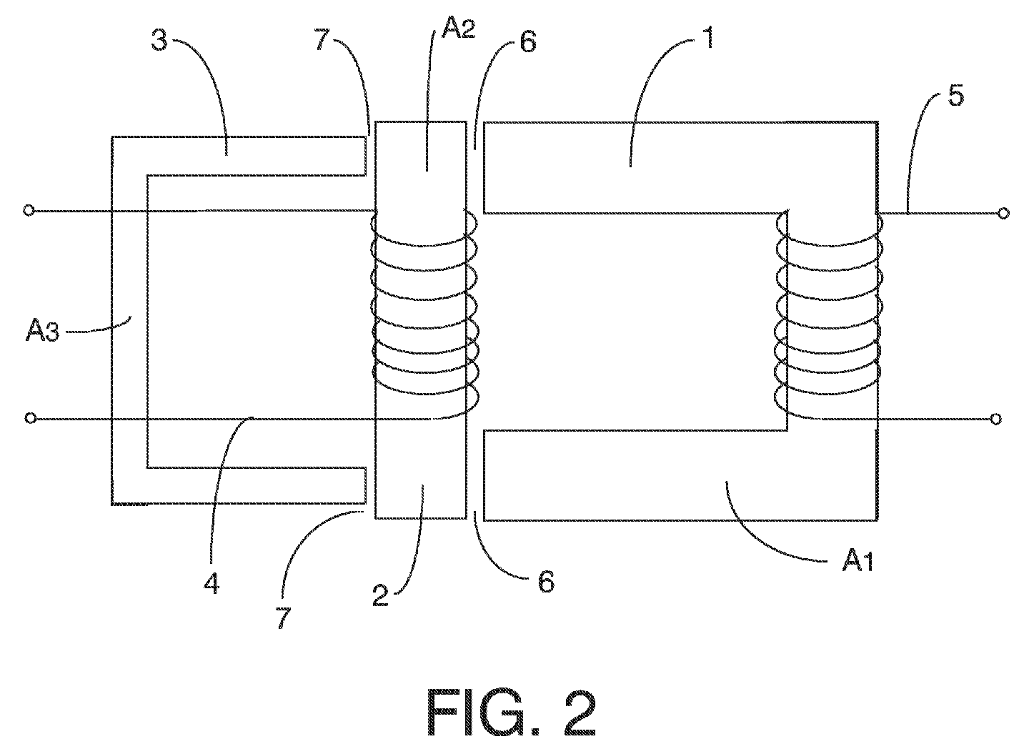
- a transformer with an integrated choke consists of a first iron core 1, the core for the primary winding 5, a second iron core 2, the core for the secondary winding 4, and a third iron core, the stray flux core 3. All three iron cores are 1,2,3 separate components and are therefore structurally separated from one another by air gaps 6, 7. Consequently the cross sections of the individual cores can be dimensioned completely independently of one another.
- the first core 1 carries the primary winding 5, while the second core 2 the Secondary winding 4 carries.
- the arrangement is designed so that the first is U-shaped designed core 1 with its open side only through an air gap 6 from the second I-shaped Core 2 is separated.
- This I-shaped core 2 in turn borders on an air gap 7 separated from the third also U-shaped core 3, which the second core 2 with the faces the open side and represents the stray flux core.
- the cores are therefore in one Row, as can also be seen in Figure 2. Since the cores 1, 2, 3 do not touch, they are mounted on a common component in a form not shown here. This component can e.g. B. be a circuit board, as is common in switching power supplies. Besides, at least the air gap 6 between the first core 1 and the second core 2 is eliminated and another medium may be present instead. In particular, the first core 1 can also be on second core 2 glued or otherwise attached.
- the so-called main permeance P h which determines the main inductance, is realized here by the air gaps 6.
- These air gaps 6 each have a cross section A h , identical to the cross section A 1 of the first core 1, and a length l h , which corresponds to the distance between the first core 1 and the second core 2.
- the central I-shaped core 2 accordingly has the cross section A 2 .
- the so-called scattering margin P s which determines the leakage inductance, is realized by the air gaps 7.
- the relationship with the currents I 1 and I 2 can be established via the two permeances and the magnetic fluxes ⁇ h and ⁇ s corresponding to the magnetic equivalent circuit diagram in FIG.
- the permeances and thus the inductances can also be freely selected over the lengths l h and l s . Nevertheless, standard cross sections can also be used here to reduce costs if each core has its own standardized cross section.
- the formation of the cores 1 and 3 in a U-shape and the core 2 in an I-shape is of course not the only conceivable solution.
- the legs of the two U-shaped cores 1 and 3 can be made shorter or lengthwise. It is also possible to arrange the core 1 or the core 3 offset from the core 2 by an angle, for example 90 °. This shortens the length of the arrangement, which then requires a larger width. Overall, however, the transformer is more compact.
Landscapes
- Engineering & Computer Science (AREA)
- Power Engineering (AREA)
- Chemical & Material Sciences (AREA)
- Composite Materials (AREA)
- Coils Or Transformers For Communication (AREA)
- Coils Of Transformers For General Uses (AREA)
Abstract
Die vorliegende Erfindung bezieht sich auf einen Transformator mit einer zusätzlichen
integrierten Drossel. Dazu ist vorgesehen, dass der Transformator mit einem ersten Kern (1),
welcher wenigstens eine Primärwicklung (5) trägt, mit einem zweiten Kern (2), welcher
wenigstens eine Sekundärwicklung (4) trägt, und mit einem dritten Kern (3) versehen ist,
wobei die Kerne (1, 2, 3) jeweils separate Bauteile sind
Description
Die vorliegende Erfindung bezieht sich auf einen Transformator mit einer zusätzlichen integrierten Drossel und auf ein Schaltnetzteil mit einem solchen Transformator.The present invention relates to a transformer with an additional one integrated choke and on a switching power supply with such a transformer.
Schaltnetzteile in Resonanzbauweise benötigen für den Resonanzkreis wenigstens ein induktives Bauelement und ein kapazitives Bauelement. Das induktive Bauelement ist meist eine Spule (Drossel), welche in Verbindung mit einem Kondensator an der Primär- oder Sekundärwicklung eines Transformators angeschlossen ist. Ein solches Schaltnetzteil in Resonanzbauweise ist aus US 4,692,851 bekannt. Hier liegt die Primärwindung in Reihe mit einer Drossel, während auf der Sekundärseite die Hauptsekundärwindung eine parallele Kapazität aufweist. Auf diese Art und Weise sorgen in der Anordnung die Induktivität der Drossel zusammen mit der Kapazität des Kondensators für die benötigten Resonanzschwingungen.Switching power supplies in resonance design require at least one for the resonance circuit inductive component and a capacitive component. The inductive component is mostly a coil (choke), which in conjunction with a capacitor on the primary or Secondary winding of a transformer is connected. Such a switching power supply in Resonance design is known from US 4,692,851. Here the primary turn is in line with a choke, while on the secondary side the main secondary turn is a parallel one Has capacity. In this way, the inductance of the device ensures Choke together with the capacitance of the capacitor for the required Resonance.
Es ist Aufgabe der vorliegenden Erfindung, einen Transformator mit einer integrierten Streuinduktivität zu versehen, so dass auf ein separates induktives Bauelement verzichtet werden kann und eine Vereinfachung im Aufbau von resonanten Schaltnetzteilen möglich ist.It is an object of the present invention to provide a transformer with an integrated To provide leakage inductance, so that a separate inductive component is dispensed with can be and simplification in the construction of resonant switching power supplies possible is.
Die Aufgabe wird erfindungsgemäß dadurch gelöst, dass ein Transformator mit einem ersten Kern, welcher wenigstens eine Primärwicklung trägt, mit einem zweiten Kern, welcher wenigstens eine Sekundärwicklung trägt, und mit einem dritten Kern versehen ist, wobei die Kerne jeweils separate Bauteile sind.The object is achieved in that a transformer with a first Core, which carries at least one primary winding, with a second core, which carries at least one secondary winding, and is provided with a third core, the Cores are separate components.
Durch die bauliche Trennung der einzelnen Kerne ist es möglich, diese jeweils auf den Hauptfluss oder den Streufluss hin zu optimieren. Trotzdem können Standardkomponenten benutzt werden, da jeder Kern nur einen Querschnitt aufweist. Dies reduziert die Herstellungskosten deutlich. Da der Hauptfluss von der sogenannten Hauptpermeanz und der Streufluss von der sogenannten Streupermeanz abhängig ist, sind diese Permeanzen entsprechend zu wählen. Die Permeanzen hängen wiederum von dem jeweiligen Luftspalt zwischen den einzelnen Kernen ab, welcher eine bestimmte Querschnittsfläche und eine bestimmte Längs aufweist. Die Kerne können allerdings auch aufeinandergeklebt sein, wenn nur eine geringe Permeanz erforderlich ist.Due to the structural separation of the individual cores, it is possible to adapt them to the To optimize the main flow or the leakage flow. Nevertheless, standard components can be used because each core has only one cross section. This reduces the Manufacturing costs significantly. Because the main flow from the so-called main permeance and the stray flux is dependent on the so-called stray permeance to choose accordingly. The permeances in turn depend on the respective air gap between the individual cores, which has a specific cross-sectional area and a has certain longitudinal. However, the cores can also be glued to one another, if only a low permeance is required.
Die Ausgestaltungen nach den Ansprüchen 2 und 3 bieten den Vorteil, dass die drei Kerne
jeweils optimal dem Fluss angepasst werden können, den sie führen. So sind sowohl die
Größen Hauptfluss als auch Streufluss separat festzulegen. Außerdem sind über die
Luftspalte zwischen den einzelnen Kernen die Streupermeanz und die Hauptpermeanz
festzulegen.The configurations according to
Die Ausgestaltung gemäß Anspruch 4 bietet den großen Vorteil, dass eine zusätzliche Spule
(Drossel) in Reihe zu entweder der Primärwindung oder der Sekundärwindung nicht
erforderlich ist. Da Resonanzschaltnetzteile eine solche Spule benötigen, ist deren Aufbau
somit vereinfacht, da ein Bauteil eingespart werden kann.The embodiment according to
Die Ausgestaltungen nach den Ansprüchen 5 bis 8 stellen besonders vorteilhafte Ausgestaltungen
der einzelnen Kerne dar.The configurations according to
Die Ausgestaltung nach Anspruch 9 erlaubt einen besonders kostengünstigen Aufbau eines erfindungsgemäßen Transformators. Die Hersteller von Magnetkernen für Transformatoren bieten alle standardisierte Querschnitte an. Magnetkerne mit anderen Querschnitten sind erheblich teurer, was in der Massenfertigung ein nicht zu unterschätzender Faktor ist. Deshalb ist es sinnvoll, auch für die drei unterschiedlich dimensionierten Magnetkerne Standardkomponenten zu verwenden.The embodiment according to claim 9 allows a particularly inexpensive construction of a transformer according to the invention. The manufacturer of magnetic cores for transformers offer all standardized cross-sections. Magnetic cores with different cross sections are considerably more expensive, which is a factor that should not be underestimated in mass production. Therefore, it makes sense for the three differently dimensioned magnetic cores Use standard components.
Mit der Ausgestaltung nach Anspruch 10 wird der Vorteil der variablen Streuinduktivität eines Transformators in einem Schaltnetzteil genutzt. Vorzugsweise ist dies ein resonantes Schaltnetzteil.With the embodiment according to claim 10, the advantage of variable leakage inductance a transformer used in a switching power supply. This is preferably a resonant one Switching power supply.
Die vorliegende Erfindung wird im folgenden an Hand eines Ausführungsbeispiels und mehrerer Figuren näher beschrieben und erläutert. Es zeigen:
- Figur 1
- ein Ersatzschaltbild des Magnetkreises in einem erfindungsgemäßen Transformator und
Figur 2- eine Seitenansicht des erfindungsgsmäßen Transformators.
- Figure 1
- an equivalent circuit diagram of the magnetic circuit in a transformer according to the invention and
- Figure 2
- a side view of the transformer according to the Invention.
Ein Transformator mit integrierter Drossel besteht aus einem ersten Eisenkern 1, dem Kern
für die Primärwicklung 5, einem zweiten Eisenkern 2, dem Kern für die Sekundärwicklung
4, und einem dritten Eisenkern, dem Streuflusskern 3. Alle drei Eisenkerne 1,2,3 sind
separate Bauteile und sind daher durch Luftspalte 6, 7 voneinander baulich getrennt. Somit
sind die Querschnitte der einzelnen Kerne völlig unabhängig voneinander dimensionierbar.
Der erste Kern 1 trägt dabei die Primärwicklung 5, während der zweite Kern 2 die
Sekundärwicklung 4 trägt. Die Anordnung ist so aufgebaut, dass der erste U-förmig
gestaltete Kern 1 mit seiner offenen Seite nur durch einen Luftspalt 6 vom zweiten I-förmigen
Kern 2 getrennt ist. Dieser I-förmige Kern 2 grenzt wiederum von einem Luftspalt
7 getrennt an den dritten auch U-förmigen Kern 3, welcher dem zweiten Kern 2 mit der
offenen Seite zugewandt ist und den Streuflusskern darstellt. Die Kerne liegen somit in einer
Reihe, wie es auch in Figur 2 zu sehen ist. Da sich die Kerne 1, 2, 3 nicht berühren, sind sie
in einer hier nicht gezeigten Form auf einem gemeinsamen Bauteil montiert. Dieses Bauteil
kann z. B. eine Platine sein, wie sie in Schaltnetzteilen üblich ist. Außerdem kann zumindest
der Luftspalt 6 zwischen dem ersten Kern 1 und dem zweiten Kern 2 entfallen und
stattdessen ein anderes Medium vorhanden sein. Insbesondere kann der erste Kern 1 auch am
zweiten Kern 2 angeklebt oder anderweitig befestigt sein.A transformer with an integrated choke consists of a first iron core 1, the core
for the
An der Primärwicklung 5 mit N1 Windungen liegt eine magnetische Spannung F1 = N1 *I1
an, während an der Sekundärwicklung 4 mit N2 Windungen entsprechend eine magnetische
Spannung F2 = N2 *I2 anliegt. Die sogenannte Hauptpermeanz Ph, welche die
Hauptinduktivität bestimmt, wird hier durch die Luftspalte 6 realisiert. Diese Luftspalte 6
haben jeweils einen Querschnitt Ah, identisch mit dem Querschnitt A1 des ersten Kerns 1,
und eine Länge lh, welche der Distanz zwischen dem ersten Kern 1 und dem zweiten Kern 2
entspricht. Der mittlere I-förmige Kern 2 hat dementsprechend den Querschnitt A2. Die
sogenannte Streupermeanz Ps, welche die Streuinduktivität bestimmt, wird durch die
Luftspalte 7 realisiert. Diese Luftspalte 7 haben jeweils einen Querschnitt As, identisch mit
dem Querschnitt A3 des dritten Kerns 3, und eine Länge ls, welche der Distanz zwischen
dem dritten Kern 3 und dem zweiten Kern 2 entspricht. Da die Luftspalte 6 und 7 jeweils
zweifach vorhanden sind ergeben sich die Permeanzen zu Ph=µ0 * Ah/2 lh für die Hauptpermeanz
Ph und zu Ps=µ0 * As /2 ls für die Streupermeanz Ps. Über die beiden Permeanzen
und die magnetischen resultierenden Flüsse Φh und Φs lässt sich entsprechend dem
magnetischen Ersatzschaltbild in Figur 1 der Zusammenhang mit den Strömen I1 und I2
herstellen, denn es gilt Φh = (F1 - F2) * Ph und Φs = F2 * Ps. Bei der erfindungsgemäßen
Anordnung können die Längen lh und ls und die Querschnitte A2, Ah (= A1) und As(=A3)
unabhängig voneinander ausgewählt werden. Dies ergibt dem Konstrukteur mehr gestalterische
Freiheiten und erlaubt eine optimale Anpassung der Querschnitte A1, A2 und A3 der
Kerne 1,2,3 an den jeweils zu leitenden resultierenden magnetischen Fluss.A magnetic voltage F 1 = N 1 * I 1 is present at the
Auch die Permeanzen und damit die Induktivitäten sind über die Längen lh und ls frei
wählbar. Trotzdem können auch hier Standardquerschnitte verwendet werden, um Kosten
zu reduzieren, wenn jeder Kern seinen eigenen standardisierten Querschnitt aufweist. Die
Ausformung der Kerne 1 und 3 in U-Form und des Kerns 2 in I-Form ist natürlich nicht die
einzige denkbare Lösung. Insbesondere können die Schenkel der beiden U-förmigen Kerne 1
und 3 kürzer oder längsr ausgsführt werden. Es ist auch möglich, den Kern 1 oder den Kern
3 gegenüber dem Kern 2 um einen Winkel z.B. 90° versetzt anzuordnen. Damit wird die
Länge der Anordnung verkürzt, wobei dann eine größere Breite notwendig ist. Insgesamt ist
damit der Transformator aber kompakter.The permeances and thus the inductances can also be freely selected over the lengths l h and l s . Nevertheless, standard cross sections can also be used here to reduce costs if each core has its own standardized cross section. The formation of the
Claims (10)
dadurch gekennzeichnet, dass der erste Kern (1) vom zweiten Kern (2) durch wenigstens einen Luftspalt (6) getrennt ist und der zweite Kern (2) vom dritten Kern (3) durch wenigstens einen weiteren Luftspalt (7) getrennt ist.Transformer according to claim 1,
characterized in that the first core (1) is separated from the second core (2) by at least one air gap (6) and the second core (2) is separated from the third core (3) by at least one further air gap (7).
dadurch gekennzeichnet, dass die Luftspalte (6, 7) derart gestaltet sind, dass der erste Kern (1) im wesentlichen einen Hauptfluss (Φh) leitet, dass der dritte Kern (3) im wesentlichen einen Streufluss (Φs) leitet und dass der zweite Kern (2) im wesentlichen die Differenz zwischen Hauptfluss und Streufluss leitet.Transformer according to claim 2,
characterized in that the air gaps (6, 7) are designed such that the first core (1) essentially guides a main flow (fluss h ), that the third core (3) essentially guides a leakage flow (Φ s ) and that the second core (2) essentially guides the difference between the main flow and the leakage flow.
dadurch gekennzeichnet, dass der Streufluss (Φs) durch den dritten Kern (3) die Wirkung einer in den Transformator integrierten Drossel hat, welche mit der Sekundärwicklung (4) in Reihe verschaltet ist.Transformer according to claim 3,
characterized in that the leakage flux (Φ s ) through the third core (3) has the effect of a choke integrated in the transformer, which is connected in series with the secondary winding (4).
dadurch gekennzeichnet, dass der erste Kern (1) U-förmig gestaltet ist. Transformer according to one of claims 1 to 4,
characterized in that the first core (1) is U-shaped.
dadurch gekennzeichnet, dass der dritte Kern (3) U-förmig gestaltet ist.Transformer according to one of claims 1 to 5,
characterized in that the third core (3) is U-shaped.
dadurch gekennzeichnet, dass der zweite Kern (2) I-förmig gestaltet ist.Transformer according to one of claims 1 to 6,
characterized in that the second core (2) is I-shaped.
dadurch gekennzeichnet, dass der erste Kern (1), der zweite Kern (2) und der dritte (3) Kern jeweils unterschiedliche Querschnitte (A1,A2,A3) aufweisen.Transformer according to one of claims 1 to 7,
characterized in that the first core (1), the second core (2) and the third (3) core each have different cross sections (A 1 , A 2 , A 3 ).
dadurch gekennzeichnet, dass der erste Kern (1), der zweite Kern (2) und der dritte (3) Kern jeweils standardisierte Querschnitte (A1,A2,A3) aufweisen.Transformer according to one of claims 1 to 8,
characterized in that the first core (1), the second core (2) and the third (3) core each have standardized cross sections (A 1 , A 2 , A 3 ).
Applications Claiming Priority (2)
| Application Number | Priority Date | Filing Date | Title |
|---|---|---|---|
| DE10119106A DE10119106A1 (en) | 2001-04-19 | 2001-04-19 | Transformer for switch-mode power supply, has three cores formed as separate components and with air gaps between |
| DE10119106 | 2001-04-19 |
Publications (3)
| Publication Number | Publication Date |
|---|---|
| EP1255346A2 true EP1255346A2 (en) | 2002-11-06 |
| EP1255346A3 EP1255346A3 (en) | 2002-12-11 |
| EP1255346B1 EP1255346B1 (en) | 2005-06-29 |
Family
ID=7681916
Family Applications (1)
| Application Number | Title | Priority Date | Filing Date |
|---|---|---|---|
| EP02100390A Expired - Lifetime EP1255346B1 (en) | 2001-04-19 | 2002-04-18 | Transformer with integrated choke coil |
Country Status (5)
| Country | Link |
|---|---|
| US (1) | US6734773B2 (en) |
| EP (1) | EP1255346B1 (en) |
| JP (1) | JP2002359122A (en) |
| AT (1) | ATE298946T1 (en) |
| DE (2) | DE10119106A1 (en) |
Families Citing this family (29)
| Publication number | Priority date | Publication date | Assignee | Title |
|---|---|---|---|---|
| CN101002377A (en) * | 2004-07-26 | 2007-07-18 | 皇家飞利浦电子股份有限公司 | Converter for providing several output voltages |
| US7598839B1 (en) | 2004-08-12 | 2009-10-06 | Pulse Engineering, Inc. | Stacked inductive device and methods of manufacturing |
| US20080074227A1 (en) * | 2006-09-21 | 2008-03-27 | Ford Global Technologies, Llc | Inductor topologies with substantial common-mode and differential-mode inductance |
| US9197132B2 (en) | 2006-12-01 | 2015-11-24 | Flextronics International Usa, Inc. | Power converter with an adaptive controller and method of operating the same |
| EP2001029B1 (en) * | 2007-06-08 | 2010-08-11 | ABB Oy | DC inductor |
| JP2009059995A (en) * | 2007-09-03 | 2009-03-19 | Fuji Electric Systems Co Ltd | Composite magnetic parts |
| US20100019875A1 (en) * | 2008-07-25 | 2010-01-28 | Ampower Technology Co., Ltd. | High voltage transformer employed in an inverter |
| US9088216B2 (en) | 2009-01-19 | 2015-07-21 | Power Systems Technologies, Ltd. | Controller for a synchronous rectifier switch |
| US9019061B2 (en) * | 2009-03-31 | 2015-04-28 | Power Systems Technologies, Ltd. | Magnetic device formed with U-shaped core pieces and power converter employing the same |
| US9077248B2 (en) | 2009-06-17 | 2015-07-07 | Power Systems Technologies Ltd | Start-up circuit for a power adapter |
| US8643222B2 (en) | 2009-06-17 | 2014-02-04 | Power Systems Technologies Ltd | Power adapter employing a power reducer |
| US8638578B2 (en) | 2009-08-14 | 2014-01-28 | Power System Technologies, Ltd. | Power converter including a charge pump employable in a power adapter |
| US8976549B2 (en) | 2009-12-03 | 2015-03-10 | Power Systems Technologies, Ltd. | Startup circuit including first and second Schmitt triggers and power converter employing the same |
| US9246391B2 (en) | 2010-01-22 | 2016-01-26 | Power Systems Technologies Ltd. | Controller for providing a corrected signal to a sensed peak current through a circuit element of a power converter |
| US8787043B2 (en) | 2010-01-22 | 2014-07-22 | Power Systems Technologies, Ltd. | Controller for a power converter and method of operating the same |
| CN102870320B (en) | 2010-03-17 | 2016-11-02 | 电力系统技术有限公司 | The control system of power converter and operational approach thereof |
| US8792257B2 (en) | 2011-03-25 | 2014-07-29 | Power Systems Technologies, Ltd. | Power converter with reduced power dissipation |
| KR101241564B1 (en) * | 2011-08-04 | 2013-03-11 | 전주대학교 산학협력단 | Couple inductor, Couple transformer and Couple inductor-transformer |
| US8792256B2 (en) | 2012-01-27 | 2014-07-29 | Power Systems Technologies Ltd. | Controller for a switch and method of operating the same |
| US9190898B2 (en) | 2012-07-06 | 2015-11-17 | Power Systems Technologies, Ltd | Controller for a power converter and method of operating the same |
| US9379629B2 (en) | 2012-07-16 | 2016-06-28 | Power Systems Technologies, Ltd. | Magnetic device and power converter employing the same |
| US9214264B2 (en) | 2012-07-16 | 2015-12-15 | Power Systems Technologies, Ltd. | Magnetic device and power converter employing the same |
| US9106130B2 (en) | 2012-07-16 | 2015-08-11 | Power Systems Technologies, Inc. | Magnetic device and power converter employing the same |
| US9099232B2 (en) | 2012-07-16 | 2015-08-04 | Power Systems Technologies Ltd. | Magnetic device and power converter employing the same |
| CN103078472B (en) * | 2012-10-25 | 2015-01-07 | 中国船舶重工集团公司第七二三研究所 | Integrated integration method for magnetic assembly of high-voltage power supply of microwave power module |
| US9240712B2 (en) | 2012-12-13 | 2016-01-19 | Power Systems Technologies Ltd. | Controller including a common current-sense device for power switches of a power converter |
| US9300206B2 (en) | 2013-11-15 | 2016-03-29 | Power Systems Technologies Ltd. | Method for estimating power of a power converter |
| US9876437B2 (en) | 2014-09-26 | 2018-01-23 | Lenovo Enterprise Solutions (Singapore) Pte. Ltd. | Interleaved transformer/inductor |
| CA3128234C (en) | 2019-02-13 | 2024-01-09 | Astronics Advanced Electronic Systems Corp. | Integrated transformer with low ac losses and impedance balanced interface |
Family Cites Families (10)
| Publication number | Priority date | Publication date | Assignee | Title |
|---|---|---|---|---|
| US3868538A (en) * | 1973-05-11 | 1975-02-25 | Zenith Radio Corp | Ferro-resonant high voltage system |
| US4613841A (en) * | 1983-11-30 | 1986-09-23 | General Electric Company | Integrated transformer and inductor |
| CA1258881A (en) * | 1987-04-15 | 1989-08-29 | Leonard Bolduc | Self-regulated transformer with gaps |
| US5155676A (en) * | 1991-11-01 | 1992-10-13 | International Business Machines Corporation | Gapped/ungapped magnetic core |
| DE4318995C2 (en) * | 1993-05-26 | 1998-10-15 | Medium Tech Gmbh | Regulated ballast with self-oscillating half-bridge circuit (electronic transformer) |
| JPH10163045A (en) * | 1996-11-29 | 1998-06-19 | Eye Lighting Syst Corp | Core for transformer, transformer for three-phase power supply and ballast for discharge lamp |
| US5889373A (en) | 1996-12-30 | 1999-03-30 | General Electric Company | Fluorescent lamp ballast with current feedback using a dual-function magnetic device |
| JPH11307377A (en) * | 1998-04-16 | 1999-11-05 | Nissin Electric Co Ltd | Insulation transformer and core unit for insulation transformer |
| DE19934767A1 (en) * | 1999-07-23 | 2001-01-25 | Philips Corp Intellectual Pty | Magnetic component |
| US6348848B1 (en) * | 2000-05-04 | 2002-02-19 | Edward Herbert | Transformer having fractional turn windings |
-
2001
- 2001-04-19 DE DE10119106A patent/DE10119106A1/en not_active Withdrawn
-
2002
- 2002-04-18 DE DE50203478T patent/DE50203478D1/en not_active Expired - Fee Related
- 2002-04-18 JP JP2002116667A patent/JP2002359122A/en not_active Withdrawn
- 2002-04-18 EP EP02100390A patent/EP1255346B1/en not_active Expired - Lifetime
- 2002-04-18 US US10/125,727 patent/US6734773B2/en not_active Expired - Fee Related
- 2002-04-18 AT AT02100390T patent/ATE298946T1/en not_active IP Right Cessation
Also Published As
| Publication number | Publication date |
|---|---|
| US6734773B2 (en) | 2004-05-11 |
| ATE298946T1 (en) | 2005-07-15 |
| DE10119106A1 (en) | 2002-10-24 |
| DE50203478D1 (en) | 2005-08-04 |
| US20020167385A1 (en) | 2002-11-14 |
| EP1255346A3 (en) | 2002-12-11 |
| EP1255346B1 (en) | 2005-06-29 |
| JP2002359122A (en) | 2002-12-13 |
Similar Documents
| Publication | Publication Date | Title |
|---|---|---|
| EP1255346B1 (en) | Transformer with integrated choke coil | |
| DE60213034T2 (en) | Umrichterwandler | |
| DE102006014608B4 (en) | Filter circuit and power supply unit | |
| DE112016005167T5 (en) | MAGNETIC COMPONENT ARRANGEMENT AND ENERGY CONVERSION DEVICE USING THE MAGNETIC COMPONENT ARRANGEMENT | |
| DE10225409B4 (en) | Current-compensated choke and circuit arrangement with the current-compensated choke | |
| EP0629311A1 (en) | COIL FOR A HIGH VOLTAGE TRANSFORMER. | |
| EP2565882B1 (en) | Inductive electronic subassembly and use of same | |
| DE102007042511A1 (en) | Coil topology with significant common mode and push-pull inductance | |
| DE102017214857B4 (en) | Toroidal core assembly, current-compensated choke and method for producing a toroidal core assembly | |
| DE102016201258A1 (en) | Electric voltage converter with several storage chokes | |
| EP3729477A1 (en) | Transformer core and transformer | |
| DE2836401C2 (en) | Stray field transformer or choke, in particular as a ballast for gas discharge lamps | |
| DE3123006A1 (en) | Transformer | |
| DE60110671T2 (en) | Umrichterwandler | |
| DE3017561C2 (en) | Switching device | |
| DE102014117551B4 (en) | Multiple choke and power converter with a multiple choke | |
| EP2817874B1 (en) | Coupling device for a multi-phase converter | |
| DE102011056667A1 (en) | Electric circuit i.e. power factor controller circuit, for use in inverter to supply electrical power from photovoltaic direct current generator into alternating current network, has storage throttle energized to produce magnetic flux | |
| EP1501106A1 (en) | Ferrite core for inductive element | |
| DE102004008961B4 (en) | Coil body for closed magnetic core, has guiding units arranged outside supporting surface, winding space defined between units and under windings, and separating units designed as flat ledges | |
| EP1856704A1 (en) | Inductive component | |
| EP0239786B1 (en) | Choke for a high power switching power supply | |
| DE3913558A1 (en) | Transformer with ferrite windings - has core with primary and secondary coils arranged on common sections in alternate manner | |
| DE2250394A1 (en) | ELECTROMAGNETIC INDUCTION DEVICE | |
| DE3632439A1 (en) | TRANSFORMER OR THROTTLE COIL |
Legal Events
| Date | Code | Title | Description |
|---|---|---|---|
| PUAI | Public reference made under article 153(3) epc to a published international application that has entered the european phase |
Free format text: ORIGINAL CODE: 0009012 |
|
| PUAL | Search report despatched |
Free format text: ORIGINAL CODE: 0009013 |
|
| AK | Designated contracting states |
Kind code of ref document: A2 Designated state(s): AT BE CH CY DE DK ES FI FR GB GR IE IT LI LU MC NL PT SE TR |
|
| AX | Request for extension of the european patent |
Free format text: AL;LT;LV;MK;RO;SI |
|
| RIC1 | Information provided on ipc code assigned before grant |
Free format text: 7H 02M 3/337 A, 7H 01F 27/24 B, 7H 01F 27/32 B, 7H 01F 38/16 B, 7G 05F 1/335 B, 7H 02M 7/5383 B, 7H 05B 39/04 B |
|
| AK | Designated contracting states |
Kind code of ref document: A3 Designated state(s): AT BE CH CY DE DK ES FI FR GB GR IE IT LI LU MC NL PT SE TR |
|
| AX | Request for extension of the european patent |
Free format text: AL;LT;LV;MK;RO;SI |
|
| RAP1 | Party data changed (applicant data changed or rights of an application transferred) |
Owner name: KONINKLIJKE PHILIPS ELECTRONICS N.V. Owner name: PHILIPS INTELLECTUAL PROPERTY & STANDARDS GMBH |
|
| 17P | Request for examination filed |
Effective date: 20030611 |
|
| AKX | Designation fees paid |
Designated state(s): AT BE CH CY DE DK ES FI FR GB GR IE IT LI LU MC NL PT SE TR |
|
| 17Q | First examination report despatched |
Effective date: 20031121 |
|
| GRAP | Despatch of communication of intention to grant a patent |
Free format text: ORIGINAL CODE: EPIDOSNIGR1 |
|
| RIN1 | Information on inventor provided before grant (corrected) |
Inventor name: ACKERMANN, BERND, DR. |
|
| GRAS | Grant fee paid |
Free format text: ORIGINAL CODE: EPIDOSNIGR3 |
|
| GRAA | (expected) grant |
Free format text: ORIGINAL CODE: 0009210 |
|
| AK | Designated contracting states |
Kind code of ref document: B1 Designated state(s): AT BE CH CY DE DK ES FI FR GB GR IE IT LI LU MC NL PT SE TR |
|
| PG25 | Lapsed in a contracting state [announced via postgrant information from national office to epo] |
Ref country code: IT Free format text: LAPSE BECAUSE OF FAILURE TO SUBMIT A TRANSLATION OF THE DESCRIPTION OR TO PAY THE FEE WITHIN THE PRESCRIBED TIME-LIMIT;WARNING: LAPSES OF ITALIAN PATENTS WITH EFFECTIVE DATE BEFORE 2007 MAY HAVE OCCURRED AT ANY TIME BEFORE 2007. THE CORRECT EFFECTIVE DATE MAY BE DIFFERENT FROM THE ONE RECORDED. Effective date: 20050629 Ref country code: IE Free format text: LAPSE BECAUSE OF FAILURE TO SUBMIT A TRANSLATION OF THE DESCRIPTION OR TO PAY THE FEE WITHIN THE PRESCRIBED TIME-LIMIT Effective date: 20050629 Ref country code: NL Free format text: LAPSE BECAUSE OF FAILURE TO SUBMIT A TRANSLATION OF THE DESCRIPTION OR TO PAY THE FEE WITHIN THE PRESCRIBED TIME-LIMIT Effective date: 20050629 Ref country code: TR Free format text: LAPSE BECAUSE OF FAILURE TO SUBMIT A TRANSLATION OF THE DESCRIPTION OR TO PAY THE FEE WITHIN THE PRESCRIBED TIME-LIMIT Effective date: 20050629 Ref country code: FI Free format text: LAPSE BECAUSE OF FAILURE TO SUBMIT A TRANSLATION OF THE DESCRIPTION OR TO PAY THE FEE WITHIN THE PRESCRIBED TIME-LIMIT Effective date: 20050629 |
|
| REG | Reference to a national code |
Ref country code: GB Ref legal event code: FG4D Free format text: NOT ENGLISH |
|
| RIN1 | Information on inventor provided before grant (corrected) |
Inventor name: ACKERMANN, BERND, DR. |
|
| REG | Reference to a national code |
Ref country code: CH Ref legal event code: EP |
|
| REF | Corresponds to: |
Ref document number: 50203478 Country of ref document: DE Date of ref document: 20050804 Kind code of ref document: P |
|
| REG | Reference to a national code |
Ref country code: IE Ref legal event code: FG4D Free format text: LANGUAGE OF EP DOCUMENT: GERMAN |
|
| PG25 | Lapsed in a contracting state [announced via postgrant information from national office to epo] |
Ref country code: SE Free format text: LAPSE BECAUSE OF FAILURE TO SUBMIT A TRANSLATION OF THE DESCRIPTION OR TO PAY THE FEE WITHIN THE PRESCRIBED TIME-LIMIT Effective date: 20050929 Ref country code: GR Free format text: LAPSE BECAUSE OF FAILURE TO SUBMIT A TRANSLATION OF THE DESCRIPTION OR TO PAY THE FEE WITHIN THE PRESCRIBED TIME-LIMIT Effective date: 20050929 Ref country code: DK Free format text: LAPSE BECAUSE OF FAILURE TO SUBMIT A TRANSLATION OF THE DESCRIPTION OR TO PAY THE FEE WITHIN THE PRESCRIBED TIME-LIMIT Effective date: 20050929 |
|
| PG25 | Lapsed in a contracting state [announced via postgrant information from national office to epo] |
Ref country code: ES Free format text: LAPSE BECAUSE OF FAILURE TO SUBMIT A TRANSLATION OF THE DESCRIPTION OR TO PAY THE FEE WITHIN THE PRESCRIBED TIME-LIMIT Effective date: 20051010 |
|
| GBT | Gb: translation of ep patent filed (gb section 77(6)(a)/1977) |
Effective date: 20050919 |
|
| NLV1 | Nl: lapsed or annulled due to failure to fulfill the requirements of art. 29p and 29m of the patents act | ||
| PG25 | Lapsed in a contracting state [announced via postgrant information from national office to epo] |
Ref country code: PT Free format text: LAPSE BECAUSE OF FAILURE TO SUBMIT A TRANSLATION OF THE DESCRIPTION OR TO PAY THE FEE WITHIN THE PRESCRIBED TIME-LIMIT Effective date: 20051207 |
|
| REG | Reference to a national code |
Ref country code: IE Ref legal event code: FD4D |
|
| ET | Fr: translation filed | ||
| PG25 | Lapsed in a contracting state [announced via postgrant information from national office to epo] |
Ref country code: GB Free format text: LAPSE BECAUSE OF NON-PAYMENT OF DUE FEES Effective date: 20060418 Ref country code: AT Free format text: LAPSE BECAUSE OF NON-PAYMENT OF DUE FEES Effective date: 20060418 |
|
| PG25 | Lapsed in a contracting state [announced via postgrant information from national office to epo] |
Ref country code: MC Free format text: LAPSE BECAUSE OF NON-PAYMENT OF DUE FEES Effective date: 20060430 Ref country code: LI Free format text: LAPSE BECAUSE OF NON-PAYMENT OF DUE FEES Effective date: 20060430 Ref country code: BE Free format text: LAPSE BECAUSE OF NON-PAYMENT OF DUE FEES Effective date: 20060430 Ref country code: CH Free format text: LAPSE BECAUSE OF NON-PAYMENT OF DUE FEES Effective date: 20060430 |
|
| PLBE | No opposition filed within time limit |
Free format text: ORIGINAL CODE: 0009261 |
|
| STAA | Information on the status of an ep patent application or granted ep patent |
Free format text: STATUS: NO OPPOSITION FILED WITHIN TIME LIMIT |
|
| 26N | No opposition filed |
Effective date: 20060330 |
|
| PG25 | Lapsed in a contracting state [announced via postgrant information from national office to epo] |
Ref country code: DE Free format text: LAPSE BECAUSE OF NON-PAYMENT OF DUE FEES Effective date: 20061101 |
|
| REG | Reference to a national code |
Ref country code: CH Ref legal event code: PL |
|
| GBPC | Gb: european patent ceased through non-payment of renewal fee |
Effective date: 20060418 |
|
| REG | Reference to a national code |
Ref country code: FR Ref legal event code: ST Effective date: 20061230 |
|
| BERE | Be: lapsed |
Owner name: PHILIPS INTELLECTUAL PROPERTY & STANDARDS G.M.B.H. Effective date: 20060430 Owner name: KONINKLIJKE PHILIPS ELECTRONICS N.V. Effective date: 20060430 |
|
| PG25 | Lapsed in a contracting state [announced via postgrant information from national office to epo] |
Ref country code: FR Free format text: LAPSE BECAUSE OF NON-PAYMENT OF DUE FEES Effective date: 20060502 |
|
| PG25 | Lapsed in a contracting state [announced via postgrant information from national office to epo] |
Ref country code: LU Free format text: LAPSE BECAUSE OF NON-PAYMENT OF DUE FEES Effective date: 20060418 |
|
| PG25 | Lapsed in a contracting state [announced via postgrant information from national office to epo] |
Ref country code: CY Free format text: LAPSE BECAUSE OF FAILURE TO SUBMIT A TRANSLATION OF THE DESCRIPTION OR TO PAY THE FEE WITHIN THE PRESCRIBED TIME-LIMIT Effective date: 20050629 |