EP1255410A2 - Système et méthode pour prise d'image couleur pour étendre la plage dynamique d'un capteur d'image - Google Patents
Système et méthode pour prise d'image couleur pour étendre la plage dynamique d'un capteur d'image Download PDFInfo
- Publication number
- EP1255410A2 EP1255410A2 EP02005049A EP02005049A EP1255410A2 EP 1255410 A2 EP1255410 A2 EP 1255410A2 EP 02005049 A EP02005049 A EP 02005049A EP 02005049 A EP02005049 A EP 02005049A EP 1255410 A2 EP1255410 A2 EP 1255410A2
- Authority
- EP
- European Patent Office
- Prior art keywords
- pixels
- color
- image data
- group
- dynamic range
- Prior art date
- Legal status (The legal status is an assumption and is not a legal conclusion. Google has not performed a legal analysis and makes no representation as to the accuracy of the status listed.)
- Withdrawn
Links
- 238000000034 method Methods 0.000 title claims abstract description 33
- 230000035945 sensitivity Effects 0.000 claims abstract description 31
- 238000003384 imaging method Methods 0.000 claims abstract description 29
- 206010034960 Photophobia Diseases 0.000 claims description 13
- 208000013469 light sensitivity Diseases 0.000 claims description 10
- 230000003287 optical effect Effects 0.000 description 7
- 230000008569 process Effects 0.000 description 6
- 230000004044 response Effects 0.000 description 5
- 239000003086 colorant Substances 0.000 description 4
- 230000012447 hatching Effects 0.000 description 3
- 238000010586 diagram Methods 0.000 description 2
- 238000001914 filtration Methods 0.000 description 2
- 238000012886 linear function Methods 0.000 description 2
- 238000001228 spectrum Methods 0.000 description 2
- 238000004364 calculation method Methods 0.000 description 1
- 238000001444 catalytic combustion detection Methods 0.000 description 1
- 230000008859 change Effects 0.000 description 1
- 230000000295 complement effect Effects 0.000 description 1
- 239000002131 composite material Substances 0.000 description 1
- 230000003247 decreasing effect Effects 0.000 description 1
- 230000006870 function Effects 0.000 description 1
- 238000005286 illumination Methods 0.000 description 1
- 229910044991 metal oxide Inorganic materials 0.000 description 1
- 150000004706 metal oxides Chemical class 0.000 description 1
- 230000000737 periodic effect Effects 0.000 description 1
- 239000004065 semiconductor Substances 0.000 description 1
- 230000002123 temporal effect Effects 0.000 description 1
Images



Classifications
-
- H—ELECTRICITY
- H04—ELECTRIC COMMUNICATION TECHNIQUE
- H04N—PICTORIAL COMMUNICATION, e.g. TELEVISION
- H04N5/00—Details of television systems
- H04N5/222—Studio circuitry; Studio devices; Studio equipment
- H04N5/262—Studio circuits, e.g. for mixing, switching-over, change of character of image, other special effects ; Cameras specially adapted for the electronic generation of special effects
- H04N5/2628—Alteration of picture size, shape, position or orientation, e.g. zooming, rotation, rolling, perspective, translation
-
- H—ELECTRICITY
- H04—ELECTRIC COMMUNICATION TECHNIQUE
- H04N—PICTORIAL COMMUNICATION, e.g. TELEVISION
- H04N23/00—Cameras or camera modules comprising electronic image sensors; Control thereof
- H04N23/70—Circuitry for compensating brightness variation in the scene
- H04N23/741—Circuitry for compensating brightness variation in the scene by increasing the dynamic range of the image compared to the dynamic range of the electronic image sensors
-
- H—ELECTRICITY
- H04—ELECTRIC COMMUNICATION TECHNIQUE
- H04N—PICTORIAL COMMUNICATION, e.g. TELEVISION
- H04N23/00—Cameras or camera modules comprising electronic image sensors; Control thereof
- H04N23/70—Circuitry for compensating brightness variation in the scene
-
- H—ELECTRICITY
- H04—ELECTRIC COMMUNICATION TECHNIQUE
- H04N—PICTORIAL COMMUNICATION, e.g. TELEVISION
- H04N23/00—Cameras or camera modules comprising electronic image sensors; Control thereof
- H04N23/80—Camera processing pipelines; Components thereof
- H04N23/84—Camera processing pipelines; Components thereof for processing colour signals
- H04N23/843—Demosaicing, e.g. interpolating colour pixel values
-
- H—ELECTRICITY
- H04—ELECTRIC COMMUNICATION TECHNIQUE
- H04N—PICTORIAL COMMUNICATION, e.g. TELEVISION
- H04N25/00—Circuitry of solid-state image sensors [SSIS]; Control thereof
- H04N25/10—Circuitry of solid-state image sensors [SSIS]; Control thereof for transforming different wavelengths into image signals
- H04N25/11—Arrangement of colour filter arrays [CFA]; Filter mosaics
- H04N25/13—Arrangement of colour filter arrays [CFA]; Filter mosaics characterised by the spectral characteristics of the filter elements
- H04N25/134—Arrangement of colour filter arrays [CFA]; Filter mosaics characterised by the spectral characteristics of the filter elements based on three different wavelength filter elements
Definitions
- the invention relates generally to digital imaging systems, and more particularly to digital imaging systems that are adapted to capture images with high contrast between bright and dark areas.
- Color digital imaging systems such as digital cameras, typically employ a single image sensor, either a charged coupled device (CCD) or a complementary metal oxide semiconductor (CMOS) device, to digitally capture a scene of interest.
- Image sensors typically include an array of tightly spaced optical detectors, such as photodiodes, that generate an electrical response in proportion to the intensity of incident light.
- the dynamic range of the individual optical detectors is defined by the minimum amount of light that is required to generate an electrical response on the low end and the maximum amount of light beyond which the electrical response of the optical detector does not change (the saturation point) on the high end.
- the dynamic range of an image sensor is an important characteristic when capturing high contrast images.
- the quality of the captured image suffers. If the sensitivity of the image sensor is adjusted (i.e., by decreasing the exposure time) to sufficiently capture the features of bright areas in an image, then the features of the dark areas are not captured. Likewise, if the sensitivity of the image sensor is adjusted (i.e., by increasing the exposure time) to sufficiently capture the features of dark areas in an image, then the features of the bright areas are not sufficiently captured.
- Fig. 1 depicts an example of a two-image technique in which the features of bright areas (i.e., background scenery) are captured in a first image 102 using a first exposure time and the features of dark areas (i.e., a person in the foreground) are captured in a second image 104 using a second exposure time.
- Features of the bright areas from the first image and features of the dark areas from the second image are then used to generate a combined image 106 that includes features of both the bright and dark areas.
- the two-image technique can extend the dynamic range of an image sensor, the technique requires enough memory to store two images before the combined image is generated and enough processing power to generate the combined image. In addition to the memory and processing requirements of the two-image technique, any changes in the scene that occur between the capturing of the first and second images will degrade the quality of the combined image.
- a method and system for extending the dynamic range of a digital imaging system involves simultaneously capturing image data from bright and dark areas of a high contrast image using an image sensor with pixels that have different sensitivities to the bright and dark areas. The image data from the different sensitivity pixels is then used to generate a final image that includes features from both the bright and dark areas. Because the technique captures all of the image data simultaneously with one image sensor, the technique requires half the time and half the memory of conventional two-image techniques. Because there is no need to merge multiple images into a final image, the technique requires less processing power and time than the two-image techniques. Additionally, because all of the image data is captured simultaneously, the temporal consistency of the image data is maintained even if the scene includes significant motion.
- An embodiment of a digital imaging system includes an image sensor with a first group of pixels that have a first sensitivity to a first color and a second group of pixels that have a second sensitivity to the same color.
- Image data that is captured by the two groups of pixels is brought to a common scale before the image data is used to generate demosaiced image data.
- the scaled image data is used in a demosaicing process to determine intensity values for the first color at all of the pixel locations. Errors in the demosaiced intensity values that result from capturing the first color image data with pixels of two different sensitivities are corrected to generate a final image that accurately depicts the original high contrast color image.
- a method for capturing a color image with a digital imaging system involves capturing color-specific image data with a first group of pixels that have a first light sensitivity and simultaneously capturing color-specific image data with a second group of pixels that have a second light sensitivity, wherein the color-specific image data from the first group of pixels and the color-specific image data from the second group of pixels are for a first color and wherein the first and second light sensitivities include a common dynamic range.
- the image data from the first group of pixels and the image data from the second group of pixels is brought to a common scale, intensity values of the first color are determined for pixels using the scaled color-specific image data, and determined intensity values that are outside the common dynamic range of the first and second groups of pixels are corrected.
- Fig. 2 depicts a digital imaging system 208 that is used to capture color digital images.
- the digital imaging system includes a shutter 210, imaging optics 212, an image sensor 214, an image processing unit 216, memory 218, and a display 220.
- the digital imaging system is a hand-held digital camera that is used to capture still digital images.
- the digital imaging system is a digital video camera that is used to capture digital video.
- the shutter 210 and imaging optics 212 are conventional devices that are well known in digital imaging systems.
- the memory 218 and display 220 are conventional devices that are well known in digital imaging systems.
- the shutter, imaging optics, memory, and display are integrated with the image sensor 214 and the image processing unit 216 into a digital camera.
- the image sensor and image processing unit are the focus of the invention and are described in more detail below.
- the image sensor 214 is an array of individual optical detectors, referred to as pixels, which individually detect light and generate electrical responses in proportion to the amount of incident light.
- Common optical detectors include CCDs and CMOS devices. Both CCD and CMOS devices are only sensitive to illumination. Consequently, these optical detectors cannot discriminate between different colors.
- a color filtering technique can be applied to separate light in terms of primary colors, typically red, green, and blue.
- a common filtering technique utilizes a color-filter array (CFA), which is overlaid on the image sensor, to separate colors of incident light in a Bayer pattern.
- a Bayer pattern is a periodic pattern with a period of two different color pixels in each dimension (vertical and horizontal).
- a single period includes either a green pixel and a red pixel, or a blue pixel and a green pixel.
- a single period includes either a green pixel and a blue pixel, or a red pixel and a green pixel.
- the number of green pixels is twice the number of red or blue pixels. The reason for the disparity in the number of green pixels is that the human eye is not equally sensitive to red, green, and blue. Consequently, more green pixels are needed to create a color image of a scene that will be perceived as a "true color" image.
- Fig. 3 depicts an array of color-specific pixels 314 that includes a distribution of green pixels (G 1 and G 2 ), with two different sensitivities.
- a Bayer pattern pixel distribution is used such that the number of green pixels is twice the number of red or blue pixels.
- one period includes a blue pixel (B) and a green pixel with a first sensitivity (G 1 ) and the other period includes a green pixel with a second sensitivity (G 2 ) and a red pixel (R).
- one period includes a blue pixel (B) and a green pixel with the second sensitivity (G 2 ) and the other period includes a green pixel with the first sensitivity (G 1 ) and a red (R) pixel.
- B blue pixel
- G 2 green pixel with the second sensitivity
- R red
- the total number of G 1 pixels is approximately equal to the total number of G 2 pixels.
- the ratio of G 1 pixels to G 2 pixels is an important factor in the error correction process described below.
- the color spectrum of the image sensor is divided into red, green, and blue, in other embodiments, the color spectrum can be divided differently.
- the G 1 pixels are more sensitive to the dark (or shadow) areas of a scene and the G 2 pixels are more sensitive to the bright (or highlight) areas of a scene. That is, the G 1 pixels are better adapted to distinguish the features in dark areas of a scene while the G 2 pixels are better adapted to distinguish the features in bright areas of a scene.
- the G 1 pixels are four times as sensitive as the G 2 pixels, such that the sensitivity ratio of the G 1 pixels to the G 2 pixels is 1:4. For example, when the G 1 and G 2 pixels are exposed to the same intensity of light for the same period of time, the G 2 pixels generate output values that are four times higher than the output values of the G 1 pixels.
- the sensitivity of the pixels is determined by amplifier circuits within the image sensor.
- the gain of the pixel amplifier circuits can be adjusted through control signals that are sent to the image sensor.
- the amplifier gain for the different color pixels is set at the center of the dynamic range of the particular color that is targeted by the pixels.
- the amplifier gain of the red pixels is set to the expected center of the red dynamic range.
- the gain of the G 1 and G 2 pixels can be adjusted to account for the expected level of contrast in the image that is to be captured. The adjusted gain of the G 1 and G 2 pixels must be reflected in the scales of the G 1 and G 2 output fields. Scaling of the pixel output fields is described in more detail below.
- Fig. 4 depicts example outputs from a G 1 pixel and a G 2 pixel relative to their minimum and maximum outputs when the pixels are subjected to the same amount of relatively bright light.
- the bright light exceeds the top end of the G 1 pixel dynamic range and therefore the output of the G 1 pixel is a value that does not accurately reflect the intensity of the incident light.
- the output of the G 1 pixel is limited to the maximum value possible in the dynamic range of the G 1 pixel. For example, if the pixel has a 10-bit output field, the output value of the G 1 pixel in the bright conditions is 1,023.
- the bright light does not exceed the dynamic range of the G 2 pixel and therefore the output of the G 2 pixel is a valid output that accurately reflects the intensity of the incident bright light. Because the G 1 pixels produce inaccurate outputs in bright conditions, errors in the image data generated from the optical sensor of Fig. 3 should be corrected in the final image. A technique for correcting the errors is described below with reference to Figs. 9 and 10.
- image data generated from the image sensor 214 is forwarded to the image processing unit 216.
- the image processing unit receives image data from the image sensor and uses the image data to generate a complete set of image data that can be used to display a final image.
- Fig. 5 is an expanded view of an embodiment of the image processing unit of Fig. 2.
- the image processing unit 516 includes a scaling unit 524, a demosaic unit 526, an error correction unit 528, and a processor 530.
- the scaling unit 524 scales the outputs from the red, green, and blue pixels so that all of the output values are on a common scale.
- Fig. 6 depicts the relative dynamic ranges of the R, G 1 , G 2 , and B pixels on a log 2 scale in the case where 10-bit output fields have been scaled to a common 12-bit output field.
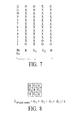
- Fig. 7 depicts the 12-bit scaled output fields of the R, G 1 , G 2 , and B pixels relative to each other.
- the G 2 pixel output values are four times higher than the G 1 pixel output values.
- the output values of the G 1 and G 2 pixels can be brought to a common scale by adding two bits (both zero) to the top end of the G 1 output field and by adding two bits (both zero) to the bottom end of the G 2 output field, such that the 12-bit output field of the G 1 pixels is: G 1 : 00 XX XX XX XX, and the 12-bit output field of the G 2 pixels is: G 2 : XX XXXXXX 00.
- the scaled G 1 pixels cover a range of values from 0-1,023 and the scaled G 2 pixels cover a range of values from 0 - 4,092.
- the total dynamic range covered by the combination of the G 1 and G 2 pixels includes values 0- 4,092. That is, the 10-bit output fields of the G 1 and G 2 pixels are synthetically made to appear as 12-bit output fields when the G 1 and G 2 pixels are used in combination on the same image sensor.
- the total dynamic range of the G 1 and G 2 pixels is 0-4,092
- the top end of the common dynamic range is set by the G 1 pixels at a maximum value of 1,023, which is the maximum value of the 12-bit output field with the two most significant bits set to zero.
- the red and blue pixels are brought to the same scale as the green pixels by adding two bits to the 10-bit output fields to make 12-bit output fields.
- the red and blue pixels are brought to the common scale by adding one bit (a zero bit) to the top end of the R and B output fields and by adding one bit (a zero bit) to the bottom end of the R and B output fields.
- the 12-bit output fields of the R and B pixels are: R and G: 0X XX XXX XXXX X0.
- the relative resolution of the R, G 1 , G 2 , and B pixels is indicated by the density of the hatching in the bars of Fig. 6. Specifically, the resolution of the G 1 pixels is the highest (as indicated by the relatively dense hatching), the resolution of the G 2 pixels is the lowest (as indicated by the relatively wide hatching), and the resolution of the R and B pixels is between the G 1 and G 2 pixels.
- the pixel values for the R, G 1 , G 2 , and B pixels are forwarded to the demosaic unit 526 as a mosaiced image.
- the demosaic unit operates to demosaic the input mosaiced image such that each pixel of the resulting demosaiced image has an intensity value for all three primary colors (red, green, and blue). That is, each pixel of the demosaiced image should have an intensity value for red, green, and blue.
- the demosaic unit estimates the missing intensity values for each pixel of the input mosaiced image using available intensity values from surrounding pixels of the same color.
- demosaicing techniques and algorithms that can be used in conjunction with the image sensor of Fig. 3 to generate a demosaiced image.
- the output of the demosaic unit is a demosaiced image that includes red, green, and blue intensity values for each pixel location.
- the green G 1 pixels are more sensitive to dark areas and will give range-limited output values (i.e., 1,023) for bright areas that exceed the top end of the G 1 pixel dynamic range.
- the range-limited output values will cause the demosaiced green intensity values that exceed the top end of the common dynamic range to be artificially low. Because some of the demosaiced intensity values related to bright areas include artificially low values, the image that is output from the demosaic unit may still lack the full dynamic range that is covered by the G 1 and G 2 pixels.
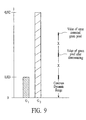
- the error correction unit 628 corrects the intensity value errors that result from using a distribution of pixels with two different sensitivities. Referring to Fig. 6, if the demosaiced green intensity value of a pixel exceeds the top end of the common dynamic range of the G 1 and G 2 pixels (i.e., point A), then it can be assumed that light incident on at least some of the G 1 pixels exceeds the top end of the G 1 pixel dynamic range. Although the light exceeds the top end of the G 1 pixel dynamic range, the output of the G 1 pixels is range-limited to 1,023 and therefore the demosaiced green intensity value is held artificially low. Because the G 2 pixels are more sensitive to bright areas, it can be assumed that the G 2 pixels give accurate output values in response to the incident light.
- the demosaiced green intensity values that exceed the common dynamic range of the G 1 and G 2 pixels represent approximately one-half of the difference between the accurate G 2 pixel values and the top end of the G 1 dynamic range. This is because one-half of the pixel values used for demosaicing are the G 2 pixel values (representing valid readings) and the other one-half of the pixel values used for demosaicing are the G 1 pixel values, which are range-limited to a maximum output value of 1,023.
- Fig. 9 depicts the error correction for a demosaiced green intensity value that exceeds the dynamic range of the G 1 pixels.
- the error corrected green intensity value is doubled such that the final demosaiced green intensity value exceeds the maximum intensity value of the G 1 pixels by 2X.
- the error corrected intensity value is determined by a linear function, in other embodiments, error corrected intensity values can be determined by a non-linear function [f(x)].
- the demosaiced green intensity values that are within the common dynamic range are not error corrected and the demosaiced green intensity values that are outside of the common dynamic range are error corrected but not beyond the top end of the G 2 dynamic range.
- the processor 530 may perform additional image processing on the capture image data.
- the processor supports the demosaic unit 526 and the error correction unit 528.
- Fig. 10 depicts a process flow diagram of a method for capturing a color image with a digital imaging system in accordance with an embodiment of the invention.
- color-specific image data is captured with a first group of pixels that have a first light sensitivity.
- color-specific image data is simultaneously captured with a second group of pixels that have a second light sensitivity, wherein the color-specific image data from the first group of pixels and the color-specific image data from the second group of pixels are for a first color and wherein the first and second light sensitivities include a common dynamic range.
- the image data from the first group of pixels and the image data from the second group of pixels are brought to a common scale.
- intensity values of the first color are determined for pixels using the color-specific image data from the first and second groups of pixels.
- determined intensity values that are outside the common dynamic range of the first and second groups of pixels are corrected.
- demosaicing can be done before the red, green, and blue pixel output values are brought to a common scale.
- the image sensor is described with pixels that have 10-bit output fields, the number of bits in the output field can be any number of bits. For example, 8-bit output fields may be used.
- a sensitivity/scaling ratio of 1:4 is described above, other sensitivity/scaling ratios may be used. For ease of scaling, ratios that are factors of two are preferred.
- the G 1 and G 2 pixels are scaled as described with reference to Figs. 6 and 7 (i.e., shifting the G 2 pixels by two bits), however for scenes with less contrast, the G 1 and G 2 pixels can be scaled by shifting the 10-bit field of the G 2 pixels by one bit similar to the R and G pixels.
- the distribution of green G 1 and G 2 pixels in the array of Fig. 3 is approximately even, in other embodiments of the array, the distribution of same-color pixels with different sensitivities may be uneven. In embodiments of uneven G 1 and G 2 pixel distribution, the function that is used to correct errors in the demosaiced green intensity values is adjusted as necessary to account for the uneven distribution. Additionally, although the green pixels are described with two different sensitivities, other color-specific pixels can be used with different sensitivities instead of, or in addition to, the green pixels.
Landscapes
- Engineering & Computer Science (AREA)
- Multimedia (AREA)
- Signal Processing (AREA)
- Physics & Mathematics (AREA)
- Spectroscopy & Molecular Physics (AREA)
- Color Television Image Signal Generators (AREA)
- Facsimile Image Signal Circuits (AREA)
- Image Input (AREA)
- Image Processing (AREA)
- Transforming Light Signals Into Electric Signals (AREA)
Applications Claiming Priority (2)
| Application Number | Priority Date | Filing Date | Title |
|---|---|---|---|
| US09/847,968 US6924841B2 (en) | 2001-05-02 | 2001-05-02 | System and method for capturing color images that extends the dynamic range of an image sensor using first and second groups of pixels |
| US847968 | 2001-05-02 |
Publications (2)
| Publication Number | Publication Date |
|---|---|
| EP1255410A2 true EP1255410A2 (fr) | 2002-11-06 |
| EP1255410A3 EP1255410A3 (fr) | 2004-05-26 |
Family
ID=25301977
Family Applications (1)
| Application Number | Title | Priority Date | Filing Date |
|---|---|---|---|
| EP02005049A Withdrawn EP1255410A3 (fr) | 2001-05-02 | 2002-03-06 | Système et méthode pour prise d'image couleur pour étendre la plage dynamique d'un capteur d'image |
Country Status (3)
| Country | Link |
|---|---|
| US (1) | US6924841B2 (fr) |
| EP (1) | EP1255410A3 (fr) |
| JP (1) | JP4161295B2 (fr) |
Cited By (6)
| Publication number | Priority date | Publication date | Assignee | Title |
|---|---|---|---|---|
| EP1575304A4 (fr) * | 2002-12-18 | 2006-05-24 | Nikon Corp | Element d'imagerie en couleurs, reseau de filtres colorés et dispositif d'imagerie en couleurs |
| EP1686810A4 (fr) * | 2003-11-11 | 2009-06-03 | Olympus Corp | Dispositif de saisie d'images multispectrales |
| US7633537B2 (en) | 2002-12-18 | 2009-12-15 | Nikon Corporation | Color image sensor, color filter array and color imaging device |
| GB2499668A (en) * | 2012-02-27 | 2013-08-28 | Apical Ltd | Exposure Controller |
| US9467628B2 (en) | 2014-08-26 | 2016-10-11 | Sensors Unlimited, Inc. | High dynamic range image sensor |
| DE10340166B4 (de) * | 2003-09-01 | 2016-12-08 | Robert Bosch Gmbh | Verfahren zur Erweiterung des Dynamik-Bereichs eines Halbleiter-Bildsensors |
Families Citing this family (61)
| Publication number | Priority date | Publication date | Assignee | Title |
|---|---|---|---|---|
| JP4088959B2 (ja) * | 2001-01-09 | 2008-05-21 | ソニー株式会社 | 画像処理装置および方法、並びに記録媒体 |
| US7308375B2 (en) * | 2001-05-14 | 2007-12-11 | Jensen Nanette C | System and method for determining light source current |
| US6989862B2 (en) * | 2001-08-23 | 2006-01-24 | Agilent Technologies, Inc. | System and method for concurrently demosaicing and resizing raw data images |
| US20030151689A1 (en) * | 2002-02-11 | 2003-08-14 | Murphy Charles Douglas | Digital images with composite exposure |
| US20030169353A1 (en) * | 2002-03-11 | 2003-09-11 | Renato Keshet | Method and apparatus for processing sensor images |
| US7034957B2 (en) * | 2002-04-15 | 2006-04-25 | Shang-Yu Yang | Method for increasing signal to noise ratio |
| JP2004048561A (ja) * | 2002-07-15 | 2004-02-12 | Fuji Photo Film Co Ltd | 撮像装置及び測光装置 |
| US7598986B2 (en) * | 2003-01-10 | 2009-10-06 | Fujifilm Corporation | Image pick-up apparatus and white balance control method |
| US7430011B2 (en) * | 2003-01-22 | 2008-09-30 | Omnivision Technologies, Inc. | Image sensor having dual automatic exposure control |
| JP4131192B2 (ja) * | 2003-04-25 | 2008-08-13 | コニカミノルタオプト株式会社 | 撮像装置、画像処理装置及び画像記録装置 |
| US7430334B2 (en) * | 2003-07-31 | 2008-09-30 | Hewlett Packard Development Company, L.P. | Digital imaging systems, articles of manufacture, and digital image processing methods |
| US7269295B2 (en) * | 2003-07-31 | 2007-09-11 | Hewlett-Packard Development Company, L.P. | Digital image processing methods, digital image devices, and articles of manufacture |
| KR101081000B1 (ko) * | 2003-10-23 | 2011-11-09 | 소니 가부시키가이샤 | 화상 처리 장치 및 화상 처리 방법과 기록 매체 |
| JP4128585B2 (ja) * | 2003-12-22 | 2008-07-30 | 三菱電機株式会社 | 画素信号処理装置及び画素信号処理方法 |
| US20050140804A1 (en) * | 2003-12-29 | 2005-06-30 | Eastman Kodak Company | Extended dynamic range image sensor capture using an array of fast and slow pixels |
| TW200702913A (en) * | 2005-06-03 | 2007-01-16 | Fujifilm Electronic Materials | Pretreatment compositions |
| JP4886248B2 (ja) * | 2005-08-31 | 2012-02-29 | キヤノン株式会社 | 焦点検出用固体撮像装置及び、同装置を用いたカメラシステム |
| US10298834B2 (en) | 2006-12-01 | 2019-05-21 | Google Llc | Video refocusing |
| US7616243B2 (en) * | 2007-03-07 | 2009-11-10 | Altasens, Inc. | Method and apparatus for improving and controlling dynamic range in an image sensor |
| JP4325703B2 (ja) * | 2007-05-24 | 2009-09-02 | ソニー株式会社 | 固体撮像装置、固体撮像装置の信号処理装置および信号処理方法、ならびに撮像装置 |
| US20090059039A1 (en) * | 2007-08-31 | 2009-03-05 | Micron Technology, Inc. | Method and apparatus for combining multi-exposure image data |
| US7884866B2 (en) * | 2007-09-14 | 2011-02-08 | Ricoh Company, Ltd. | Imaging apparatus and imaging method |
| JP5103341B2 (ja) * | 2007-09-28 | 2012-12-19 | 富士フイルム株式会社 | 固体撮像素子及び撮像装置 |
| JP5045421B2 (ja) * | 2007-12-21 | 2012-10-10 | ソニー株式会社 | 撮像装置、色ノイズ低減方法および色ノイズ低減プログラム |
| KR101639382B1 (ko) * | 2008-08-27 | 2016-07-13 | 삼성전자주식회사 | 높은 동적 범위를 가지는 영상을 생성하는 장치 및 방법 |
| US8218068B2 (en) * | 2009-04-01 | 2012-07-10 | Omnivision Technologies, Inc. | Exposing pixel groups in producing digital images |
| US8605177B2 (en) * | 2009-09-16 | 2013-12-10 | Altasens, Inc. | Image sensor with wide dynamic range |
| JP2012034350A (ja) * | 2010-07-07 | 2012-02-16 | Canon Inc | 固体撮像装置及び撮像システム |
| JP5697371B2 (ja) | 2010-07-07 | 2015-04-08 | キヤノン株式会社 | 固体撮像装置および撮像システム |
| JP5643555B2 (ja) | 2010-07-07 | 2014-12-17 | キヤノン株式会社 | 固体撮像装置及び撮像システム |
| JP5656484B2 (ja) | 2010-07-07 | 2015-01-21 | キヤノン株式会社 | 固体撮像装置および撮像システム |
| JP5885401B2 (ja) | 2010-07-07 | 2016-03-15 | キヤノン株式会社 | 固体撮像装置および撮像システム |
| JP5751766B2 (ja) | 2010-07-07 | 2015-07-22 | キヤノン株式会社 | 固体撮像装置および撮像システム |
| US8415623B2 (en) | 2010-11-23 | 2013-04-09 | Raytheon Company | Processing detector array signals using stacked readout integrated circuits |
| JP2013077879A (ja) * | 2011-09-29 | 2013-04-25 | Sony Corp | 撮像装置と撮像方法およびプログラム |
| US8432466B2 (en) * | 2011-09-29 | 2013-04-30 | International Business Machines Corporation | Multiple image high dynamic range imaging from a single sensor array |
| US8948545B2 (en) * | 2012-02-28 | 2015-02-03 | Lytro, Inc. | Compensating for sensor saturation and microlens modulation during light-field image processing |
| US9858649B2 (en) | 2015-09-30 | 2018-01-02 | Lytro, Inc. | Depth-based image blurring |
| JP6029430B2 (ja) * | 2012-11-20 | 2016-11-24 | キヤノン株式会社 | 画像処理装置及び画像処理方法 |
| US10334151B2 (en) | 2013-04-22 | 2019-06-25 | Google Llc | Phase detection autofocus using subaperture images |
| US10419737B2 (en) | 2015-04-15 | 2019-09-17 | Google Llc | Data structures and delivery methods for expediting virtual reality playback |
| US11328446B2 (en) | 2015-04-15 | 2022-05-10 | Google Llc | Combining light-field data with active depth data for depth map generation |
| US10546424B2 (en) | 2015-04-15 | 2020-01-28 | Google Llc | Layered content delivery for virtual and augmented reality experiences |
| US10341632B2 (en) | 2015-04-15 | 2019-07-02 | Google Llc. | Spatial random access enabled video system with a three-dimensional viewing volume |
| US10412373B2 (en) | 2015-04-15 | 2019-09-10 | Google Llc | Image capture for virtual reality displays |
| US10275898B1 (en) | 2015-04-15 | 2019-04-30 | Google Llc | Wedge-based light-field video capture |
| US10444931B2 (en) | 2017-05-09 | 2019-10-15 | Google Llc | Vantage generation and interactive playback |
| US10440407B2 (en) | 2017-05-09 | 2019-10-08 | Google Llc | Adaptive control for immersive experience delivery |
| US10567464B2 (en) | 2015-04-15 | 2020-02-18 | Google Llc | Video compression with adaptive view-dependent lighting removal |
| US10565734B2 (en) | 2015-04-15 | 2020-02-18 | Google Llc | Video capture, processing, calibration, computational fiber artifact removal, and light-field pipeline |
| US10469873B2 (en) | 2015-04-15 | 2019-11-05 | Google Llc | Encoding and decoding virtual reality video |
| US10540818B2 (en) | 2015-04-15 | 2020-01-21 | Google Llc | Stereo image generation and interactive playback |
| US9979909B2 (en) | 2015-07-24 | 2018-05-22 | Lytro, Inc. | Automatic lens flare detection and correction for light-field images |
| US10298888B2 (en) * | 2015-08-25 | 2019-05-21 | Kabushiki Kaisha Toshiba | Adaptive analyzer of sensitivity difference of same color pixels and adaptive corrector of sensitivity difference of same color pixels |
| US10275892B2 (en) | 2016-06-09 | 2019-04-30 | Google Llc | Multi-view scene segmentation and propagation |
| US10679361B2 (en) | 2016-12-05 | 2020-06-09 | Google Llc | Multi-view rotoscope contour propagation |
| US10594945B2 (en) | 2017-04-03 | 2020-03-17 | Google Llc | Generating dolly zoom effect using light field image data |
| US10474227B2 (en) | 2017-05-09 | 2019-11-12 | Google Llc | Generation of virtual reality with 6 degrees of freedom from limited viewer data |
| US10354399B2 (en) | 2017-05-25 | 2019-07-16 | Google Llc | Multi-view back-projection to a light-field |
| US10545215B2 (en) | 2017-09-13 | 2020-01-28 | Google Llc | 4D camera tracking and optical stabilization |
| US10965862B2 (en) | 2018-01-18 | 2021-03-30 | Google Llc | Multi-camera navigation interface |
Citations (2)
| Publication number | Priority date | Publication date | Assignee | Title |
|---|---|---|---|---|
| JPH10189930A (ja) | 1996-12-20 | 1998-07-21 | Ricoh Co Ltd | 固体撮像素子 |
| WO2000079784A1 (fr) | 1999-06-04 | 2000-12-28 | The Trustees Of Columbia University In The City Of New York | Procede et dispositif d'imagerie a plage dynamique haute par utilisation d'expositions variant spatialement |
Family Cites Families (13)
| Publication number | Priority date | Publication date | Assignee | Title |
|---|---|---|---|---|
| US4647975A (en) * | 1985-10-30 | 1987-03-03 | Polaroid Corporation | Exposure control system for an electronic imaging camera having increased dynamic range |
| US6204881B1 (en) * | 1993-10-10 | 2001-03-20 | Canon Kabushiki Kaisha | Image data processing apparatus which can combine a plurality of images at different exposures into an image with a wider dynamic range |
| US6388709B1 (en) * | 1995-04-21 | 2002-05-14 | Canon Kabushiki Kaisha | Image sensing apparatus with optical modulation elements having transmission characteristics controllable by pixel |
| DE69628187D1 (de) * | 1995-11-07 | 2003-06-18 | California Inst Of Techn | Bildsensor mit linearem ausgang mit grossem dynamikbereich |
| US6275259B1 (en) * | 1998-02-02 | 2001-08-14 | International Business Machines Corporation | Digital automatic gain control circuit for image system |
| US6137100A (en) * | 1998-06-08 | 2000-10-24 | Photobit Corporation | CMOS image sensor with different pixel sizes for different colors |
| US6724426B1 (en) * | 1999-03-08 | 2004-04-20 | Micron Technology, Inc. | Multi junction APS with dual simultaneous integration |
| US6697114B1 (en) * | 1999-08-13 | 2004-02-24 | Foveon, Inc. | Triple slope pixel sensor and arry |
| US6710804B1 (en) * | 2000-01-18 | 2004-03-23 | Eastman Kodak Company | CMOS active pixel image sensor with extended dynamic range and sensitivity |
| US6909461B1 (en) * | 2000-07-13 | 2005-06-21 | Eastman Kodak Company | Method and apparatus to extend the effective dynamic range of an image sensing device |
| US6765611B1 (en) * | 2000-11-21 | 2004-07-20 | Eastman Kodak Company | Method for compressing an image from a sparsely sampled extended dynamic range image sensing device |
| US6646246B1 (en) * | 2000-11-21 | 2003-11-11 | Eastman Kodak Company | Method and system of noise removal for a sparsely sampled extended dynamic range image sensing device |
| US6943831B2 (en) * | 2001-01-24 | 2005-09-13 | Eastman Kodak Company | Method and apparatus to extend the effective dynamic range of an image sensing device and use residual images |
-
2001
- 2001-05-02 US US09/847,968 patent/US6924841B2/en not_active Expired - Lifetime
-
2002
- 2002-03-06 EP EP02005049A patent/EP1255410A3/fr not_active Withdrawn
- 2002-04-25 JP JP2002123538A patent/JP4161295B2/ja not_active Expired - Fee Related
Patent Citations (2)
| Publication number | Priority date | Publication date | Assignee | Title |
|---|---|---|---|---|
| JPH10189930A (ja) | 1996-12-20 | 1998-07-21 | Ricoh Co Ltd | 固体撮像素子 |
| WO2000079784A1 (fr) | 1999-06-04 | 2000-12-28 | The Trustees Of Columbia University In The City Of New York | Procede et dispositif d'imagerie a plage dynamique haute par utilisation d'expositions variant spatialement |
Cited By (12)
| Publication number | Priority date | Publication date | Assignee | Title |
|---|---|---|---|---|
| EP1575304A4 (fr) * | 2002-12-18 | 2006-05-24 | Nikon Corp | Element d'imagerie en couleurs, reseau de filtres colorés et dispositif d'imagerie en couleurs |
| US7633537B2 (en) | 2002-12-18 | 2009-12-15 | Nikon Corporation | Color image sensor, color filter array and color imaging device |
| DE10340166B4 (de) * | 2003-09-01 | 2016-12-08 | Robert Bosch Gmbh | Verfahren zur Erweiterung des Dynamik-Bereichs eines Halbleiter-Bildsensors |
| EP1686810A4 (fr) * | 2003-11-11 | 2009-06-03 | Olympus Corp | Dispositif de saisie d'images multispectrales |
| US7612822B2 (en) | 2003-11-11 | 2009-11-03 | Olympus Corporation | Multispectral image capturing apparatus |
| US7868936B2 (en) | 2003-11-11 | 2011-01-11 | Olympus Corporation | Multispectral image capturing apparatus |
| US8134618B2 (en) | 2003-11-11 | 2012-03-13 | Olympus Corporation | Multispectral image capturing apparatus |
| GB2499668A (en) * | 2012-02-27 | 2013-08-28 | Apical Ltd | Exposure Controller |
| US9584732B2 (en) | 2012-02-27 | 2017-02-28 | Apical, Ltd. | Exposure controller |
| GB2499668B (en) * | 2012-02-27 | 2019-03-06 | Apical Ltd | Exposure controller |
| US9467628B2 (en) | 2014-08-26 | 2016-10-11 | Sensors Unlimited, Inc. | High dynamic range image sensor |
| BE1023383B1 (fr) * | 2014-08-26 | 2017-03-01 | Sensors Unlimited, Inc. | Capteur d'image à grande gamme dynamique |
Also Published As
| Publication number | Publication date |
|---|---|
| US6924841B2 (en) | 2005-08-02 |
| US20020163583A1 (en) | 2002-11-07 |
| JP4161295B2 (ja) | 2008-10-08 |
| EP1255410A3 (fr) | 2004-05-26 |
| JP2003022440A (ja) | 2003-01-24 |
Similar Documents
| Publication | Publication Date | Title |
|---|---|---|
| US6924841B2 (en) | System and method for capturing color images that extends the dynamic range of an image sensor using first and second groups of pixels | |
| CN111629140B (zh) | 图像传感器和电子设备 | |
| US8199229B2 (en) | Color filter, image processing apparatus, image processing method, image-capture apparatus, image-capture method, program and recording medium | |
| US7151560B2 (en) | Method and apparatus for producing calibration data for a digital camera | |
| KR101442313B1 (ko) | 카메라 센서 교정 | |
| US7756330B2 (en) | Producing an extended dynamic range digital image | |
| CN204498282U (zh) | 具有可见光感光像素和红外光感光像素的成像系统 | |
| US8743208B2 (en) | Method and apparatus for image noise reduction using noise models | |
| EP1209903B1 (fr) | Procédé et appareil pour la suppression de bruit d'une image à dynamique étendue échantillonnée de façon éparse | |
| US8125543B2 (en) | Solid-state imaging device and imaging apparatus with color correction based on light sensitivity detection | |
| JP5155324B2 (ja) | 被写体運動ぶれが低減されたデジタル画像 | |
| EP1206130B1 (fr) | Procédé et appareil pour produire une image de basse resolution à partir d'une image à dynamique étendue échantillonnée de façon éparse | |
| EP1206119A2 (fr) | Procédé et appareil de commande de l'exposition pour un capteur d'image à gamme dynamique étendue | |
| US20080278591A1 (en) | Method and apparatus for improving low-light performance for small pixel image sensors | |
| EP1389771A2 (fr) | Système et procédé de traitement d'images numériques permettant de combiner une operation de démosaiquage et une correction de mauvais pixels | |
| US8564688B2 (en) | Methods, systems and apparatuses for white balance calibration | |
| US20030063185A1 (en) | Three-dimensional imaging with complementary color filter arrays | |
| JP5414691B2 (ja) | 画像処理装置及び画像処理方法 | |
| US20030184673A1 (en) | Automatic exposure control for digital imaging | |
| CN111885281A (zh) | 图像处理 | |
| US7146040B2 (en) | Automatic white balance technique | |
| EP1484928B1 (fr) | Dispositif de prise d'images | |
| JP2002112276A (ja) | カラー固体撮像装置 | |
| WO2022073364A1 (fr) | Procédé et appareil d'obtention d'images, terminal, et support de stockage lisible par ordinateur | |
| CN110602420A (zh) | 相机、黑电平调整方法及装置 |
Legal Events
| Date | Code | Title | Description |
|---|---|---|---|
| PUAI | Public reference made under article 153(3) epc to a published international application that has entered the european phase |
Free format text: ORIGINAL CODE: 0009012 |
|
| AK | Designated contracting states |
Kind code of ref document: A2 Designated state(s): AT BE CH CY DE DK ES FI FR GB GR IE IT LI LU MC NL PT SE TR |
|
| AX | Request for extension of the european patent |
Free format text: AL;LT;LV;MK;RO;SI |
|
| PUAL | Search report despatched |
Free format text: ORIGINAL CODE: 0009013 |
|
| AK | Designated contracting states |
Kind code of ref document: A3 Designated state(s): AT BE CH CY DE DK ES FI FR GB GR IE IT LI LU MC NL PT SE TR |
|
| AX | Request for extension of the european patent |
Extension state: AL LT LV MK RO SI |
|
| 17P | Request for examination filed |
Effective date: 20040513 |
|
| AKX | Designation fees paid |
Designated state(s): DE FR GB |
|
| RAP1 | Party data changed (applicant data changed or rights of an application transferred) |
Owner name: AGILENT TECHNOLOGIES, INC. |
|
| RAP1 | Party data changed (applicant data changed or rights of an application transferred) |
Owner name: MICRON TECHNOLOGY, INC. |
|
| 17Q | First examination report despatched |
Effective date: 20090304 |
|
| STAA | Information on the status of an ep patent application or granted ep patent |
Free format text: STATUS: THE APPLICATION IS DEEMED TO BE WITHDRAWN |
|
| 18D | Application deemed to be withdrawn |
Effective date: 20130522 |