EP1255497B1 - Verriegelungsnagel und zielgerät - Google Patents
Verriegelungsnagel und zielgerät Download PDFInfo
- Publication number
- EP1255497B1 EP1255497B1 EP00969472A EP00969472A EP1255497B1 EP 1255497 B1 EP1255497 B1 EP 1255497B1 EP 00969472 A EP00969472 A EP 00969472A EP 00969472 A EP00969472 A EP 00969472A EP 1255497 B1 EP1255497 B1 EP 1255497B1
- Authority
- EP
- European Patent Office
- Prior art keywords
- cross
- nail
- bore
- distal
- bores
- Prior art date
- Legal status (The legal status is an assumption and is not a legal conclusion. Google has not performed a legal analysis and makes no representation as to the accuracy of the status listed.)
- Expired - Lifetime
Links
Images
Classifications
-
- A—HUMAN NECESSITIES
- A61—MEDICAL OR VETERINARY SCIENCE; HYGIENE
- A61B—DIAGNOSIS; SURGERY; IDENTIFICATION
- A61B17/00—Surgical instruments, devices or methods
- A61B17/16—Instruments for performing osteoclasis; Drills or chisels for bones; Trepans
- A61B17/17—Guides or aligning means for drills, mills, pins or wires
- A61B17/1725—Guides or aligning means for drills, mills, pins or wires for applying transverse screws or pins through intramedullary nails or pins
-
- A—HUMAN NECESSITIES
- A61—MEDICAL OR VETERINARY SCIENCE; HYGIENE
- A61B—DIAGNOSIS; SURGERY; IDENTIFICATION
- A61B17/00—Surgical instruments, devices or methods
- A61B17/56—Surgical instruments or methods for treatment of bones or joints; Devices specially adapted therefor
- A61B17/58—Surgical instruments or methods for treatment of bones or joints; Devices specially adapted therefor for osteosynthesis, e.g. bone plates, screws or setting implements
- A61B17/68—Internal fixation devices, including fasteners and spinal fixators, even if a part thereof projects from the skin
- A61B17/72—Intramedullary devices, e.g. pins or nails
Definitions
- the invention relates to a Implantation system with a locking nail and a target device according to claim 1.
- Locking nails for the treatment of fractures of long bones are widespread. Their application is roughly in "The Journal of Trauma” by 1993 Vol. 35 No. 5, pages 772-775.
- Typical of such Locking nails is the arrangement of two transverse holes at the distal End and at least one transverse bore at the proximal end. By the Cross holes are passed through bone screws. They are on opposite sides Sides screwed into the cortex. This is the result Locking nail secured axially and against rotation.
- a problem with using such locking nails is. To identify the location of transverse bores to the cortical bone from the outside in the right place. There are a number of target devices known become. who work with x-rays. around the location of the cross holes relative to a target device. It is therefore possible. With Help the target device and a so-called drill or target sleeve the bone in the right place. The well-known target devices become usually firmly connected to the proximal end of the nail. To this Way can be almost exactly pretend the position of the transverse holes. However, it should be noted that due to the curvature of the bone and by the possible twist of the nail when driving the assumed location of the cross holes not with the actual matches.
- the invention has for its object to a locking nail create, with which is possible, even without fluoroscopic to simple Way to determine the location of the distal transverse bores.
- an axially parallel groove in the outside of the nail formed. It extends on both sides of at least that transverse bore, nearest to the distal end of the nail.
- the longitudinal axis the groove intersects the axis of the hole approximately vertically.
- the Groove is preferably according to an embodiment of the invention in cross section U-shaped, preferably rounded in the bottom.
- the groove extends distally and proximally over both transverse bores out.
- the maximum width of the groove can be smaller than the diameter of the
- the distal end of the locking nail cylindrically shaped.
- the end can be either hollow or solid his.
- the invention provides a suitable target device in front. It has a handle portion which in the conventional manner with the proximal end of the locking nail is connectable to it to the locking nail set in the axial and rotational direction. With the handle section is also a target rod connectable, releasably attachable to the handle portion is, however, fixed axially and rotationally stable in the attached state is.
- the aiming rod extends parallel and at a distance from the locking nail, when the latter is attached to the handle portion.
- the target rod extends thus externally parallel to the limb whose bones are being supplied should.
- the target rod has two transverse bores whose distance corresponds to the transverse bores of the locking nail. They are however in the Diameter larger, as known per se, a drill or target sleeve to be able to record.
- the distal Section of the target rod consists of an elastically yielding material, for example, from a corresponding plastic, preferably PTFE.
- the distal portion is preferably cylindrically shaped.
- the proximal one On the other hand, part of the target rod is made of a relatively rigid material, for example, made of metal, a rotationally stable recording in the handle portion to enable.
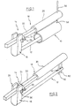
- a tubular bone 10 is indicated, with the help of a only indicated drawn locking nail 12 to be supplied.
- Targeting device 14 which is indicated in Fig. 1, has a grip portion 16, with the proximal end of the nail 12 axially and rotationally fixedly connected is. The type of connection is not shown. She is known.
- Parallel to the nail 12 extends a target rod 18, which consists of a distal portion 20 and a proximal portion 22.
- the proximal section 22 is a square metal.
- the distal portion 20 is cylindrical and molded from a resilient plastic material, such as PTFE. Sections 20, 22 are suitable but not shown connected with each other.
- a locking ring 24 On the portion 22 of the target rod 18 is rotatably a locking ring 24, which, however, is axially displaceable, wherein the axial position can be determined by means of a locking screw 26.
- the grip section 16 has a bifurcated portion 28, wherein the gap between the legs is dimensioned so that the square section 22 received fitting is.
- Another locking screw 30 serves to the square section 22 in the fork section 28 set.
- the locking nail 12 with two distal Cross holes provided, as known.
- the distal section of the locking nail is designated 32 and the transverse bores have the reference numerals 34 and 36.
- a groove 40 is formed outside in the distal portion 32.
- the paraxial extends and beyond the bores 34, 36 each to the distal or extending proximally.
- the extension on both sides of the bores 34, 36 amounts to e.g. 5 mm.
- the groove 40 also extends into the bores 34, 36th into it. From Figs. 9 and 10 it is apparent that the groove is approximately U-shaped Has cross-section and rounded in the bottom. She has a something smaller width than the diameter of the transverse bores 34, 36th
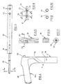
- the target bar 18 is shown more clearly.
- the square section 22 partly in the material of the distal portion 20 is embedded.
- Distal points to the distal section 20 two transverse holes 42, 44 on.
- the distance between their axes corresponds the distance of the axes of the transverse bores 36, 34 (the drawings are not to scale).
- the diameter of the transverse bores 42, 44 is larger as the diameter of the transverse bores 34, 36, since they are also a sleeve need to record on which a drill can be introduced, what will be discussed in more detail below.
- the grip portion 16a of FIG. 4 differs from that of FIG. 1 and 2 in that it is angular. He points at the upper right end of the Handle 48 a cone 50 on which the locking nail, not shown is postponed. The remaining attachment of the locking nail is, as already mentioned, not described.
- the grip portion 16a like the grip portion 16, has a fork portion 28 on to the appropriate recording of the square section 22.
- Fig. 5 is a threaded transverse bore 52 can be seen for receiving the Locking screw 30 of FIG. 2.
- the handle portion 16a has an oblique Through hole 54, whose function is not discussed.
- the target rod 18 can be fixed in its axial position so that his Quer carefullybohrept 42, 44 to the suspected location of the implanted Locking nail or its transverse bores 34, 36 are aligned. In Reality, however, can be achieved by bending the locking nail 12 or by a twist the actual position of the transverse bores 34, 36 a different one his. In any case, in the target process, first of the presumed situation. In this one will then use a drill 56 as shown in FIG. 1 in the bone 10 made a bore 58, and although only in the associated bone wall.
- the Target rod 18 removed.
- the surgeon performs a drill of smaller size Diameter (previously he may have used a 5.5mm drill and the following drill and pin have a diameter of 3.5 mm) by hand through the bone hole until it feels the nail. If the operator does not feel the transverse bore 34, the nail 12 becomes turned slightly until the operator feels the groove 40. After that, the nail becomes 12 moves back and forth until the drill shaft or the wire pin easy to introduce further. After that can also be the opposite cortex drilled and then screwed the bone screw. The shaft of the screwdriver remains on the screw, and the target rod 18 is then in the handle portion 16 and 16 a in a reproducible position established.
- the distal portion 20 is optionally twisted or deformed, although the nail when driving a deformation or Suffered torsion.
- the second transverse bore 42 of the distal portion 20 is then aligned exactly to the second transverse bore 36 of the nail 12, so that now also the cortex for the second transverse bore 36 drilled can not be subsequently screwed with the help of the shown second bone screw.
- the locking nail 12 can also be known per se proximally Way to be locked. It is unlikely that in this area a deformation has taken place. Therefore, one on the target rod 18 is correct provided bore (not shown) in each case with the proximal Cross hole of the nail 12 match. Here, therefore, arise for the surgeon no difficulties.
Landscapes
- Health & Medical Sciences (AREA)
- Surgery (AREA)
- Orthopedic Medicine & Surgery (AREA)
- Life Sciences & Earth Sciences (AREA)
- Heart & Thoracic Surgery (AREA)
- Veterinary Medicine (AREA)
- Engineering & Computer Science (AREA)
- Biomedical Technology (AREA)
- Nuclear Medicine, Radiotherapy & Molecular Imaging (AREA)
- Medical Informatics (AREA)
- Molecular Biology (AREA)
- Animal Behavior & Ethology (AREA)
- General Health & Medical Sciences (AREA)
- Public Health (AREA)
- Neurology (AREA)
- Dentistry (AREA)
- Oral & Maxillofacial Surgery (AREA)
- Surgical Instruments (AREA)
Abstract
Description
- Fig.
- 1 zeigt äußerst schematisch perspektivisch ein Zielgerät nach der Erfindung und einen Knochennagel in einem schematisch angedeuteten Röhrenknochen.
- Fig. 2
- zeigt äußerst schematisch perspektivisch das Zielgerät nach Fig. 1 in vollständiger Gestalt.
- Fig. 3
- zeigt eine Seitenansicht des Zielstabs des Zielgeräts nach den Fig. 1 und 2.
- Fig. 4
- zeigt eine Seitenansicht des gegenüber den Fig. 1 und 2 abgewandelten Griffabschnitts des Zielgeräts.
- Fig. 5
- zeigt einen Teil des Griffabschnitts nach Fig. 4 in der Seitenansicht gemäß Pfeil 5.
- Fig. 6
- zeigt einen Schnitt durch die Darstellung nach Fig. 5 entlang der Linie 6-6.
- Fig. 7
- zeigt einen Schnitt durch den Zielstab nach Fig. 3 entlang der Linie 7-7.
- Fig. 8
- zeigt das distale Ende des Verriegelungsnagels nach der Erfindung.
- Fig. 9
- zeigt einen Schnitt durch den Nagelabschnitt nach Fig. 8 entlang der Linie 9-9.
- Fig. 10
- zeigt einen Schnitt durch den Nagelabschnitt nach Fig. 8 entlang der Linie 10-10.
Claims (3)
- Implantationssystem miteinem Verriegelungsnagel (12) zur Versorgung von Frakturen von Röhrenknochen, der am distalen Ende distal beabstandete, parallele Querbohrungen (34, 36) und am proximalen Ende mindestens eine weitere Querbohrung aufweist zur Aufnahme von Knochenschrauben, wobei im distalen Abschnitt (32) des Verriegelungsnagels (12) eine achsparallele Nut (40) in die Außenseite des Nagels (12) eingeformt ist, die sich zu beiden Seiten der Querbohrung (34), in diese übergehend, erstreckt, jedoch nur ein wenig distal über die dem distalen Ende nächstgelegene Querbohrung (34) und nur ein wenig proximal über die dem proximalen Ende des Nagels nächstgelegene distale Querbohrung, wobei die Längsachse der Nut (40) die Achse der Querbohrungen (34, 36) annähernd schneidet, die Nut im Querschnitt U-förmig ist und ihre maximale Breite kleiner ist als der Durchmesser der Querbohrungen (34, 36),einem Zielgerät (14) für den Verriegelungsnagel (12), der einen Griffabschnitt (16, 16a) aufweist mit Mitteln zur Festlegung des proximalen Endes des Verriegelungsnagels (12) in axialer und Drehrichtung sowie einen Zielabschnitt (18), der an einem Ende axial und drehfest am Griffabschnitt (16, 16a) befestigt ist, der sich annähernd parallel zum und im Abstand vom eingespannten Verriegelungsnagel (12) erstreckt und am distalen Ende Querbohrungen aufweist, die zu den Querbohrungen (34, 36) im Verriegelungsnagel (12) ausrichtbar sind,einem durch eine Querbohrung des Zielabschnitts (18) hindurchführbaren Bohrer (56) zum Aufbohren der nächstgelegenen Wand des Knochens undeinem Stift oder einem Bohrer mit kleinerem Durchmesser als der erste Bohrer zum Ertasten der Nut (40) und einer der Querbohrungen (34, 36) des Verriegelungsnagels (12).
- Implantationssystem nach Anspruch 1, dadurch gekennzeichnet, daß der distale Abschnitt (32) des Nagels (12) zylindrisch geformt ist.
- Implantationssystem nach Anspruch 1 oder 2, dadurch gekennzeichnet, daß die Nut (40) sich etwa 5 mm über die Querbohrungen (34, 36) hinaus nach distal und proximal erstreckt.
Applications Claiming Priority (3)
| Application Number | Priority Date | Filing Date | Title |
|---|---|---|---|
| DE20003053U | 2000-02-19 | ||
| DE20003053U DE20003053U1 (de) | 2000-02-19 | 2000-02-19 | Verriegelungsnagel und Zielgerät |
| PCT/EP2000/009935 WO2001060272A1 (de) | 2000-02-19 | 2000-10-10 | Verriegelungsnagel und zielgerät |
Publications (2)
| Publication Number | Publication Date |
|---|---|
| EP1255497A1 EP1255497A1 (de) | 2002-11-13 |
| EP1255497B1 true EP1255497B1 (de) | 2004-06-23 |
Family
ID=7937609
Family Applications (1)
| Application Number | Title | Priority Date | Filing Date |
|---|---|---|---|
| EP00969472A Expired - Lifetime EP1255497B1 (de) | 2000-02-19 | 2000-10-10 | Verriegelungsnagel und zielgerät |
Country Status (7)
| Country | Link |
|---|---|
| US (1) | US7060070B1 (de) |
| EP (1) | EP1255497B1 (de) |
| JP (1) | JP3781185B2 (de) |
| AU (1) | AU2000279176A1 (de) |
| DE (2) | DE20003053U1 (de) |
| ES (1) | ES2220549T3 (de) |
| WO (1) | WO2001060272A1 (de) |
Families Citing this family (8)
| Publication number | Priority date | Publication date | Assignee | Title |
|---|---|---|---|---|
| DE10227379B4 (de) * | 2002-06-20 | 2005-12-08 | Stryker Trauma Gmbh | Implantationssystem und Zielgerät dafür |
| WO2010123879A1 (en) * | 2009-04-20 | 2010-10-28 | Virginia Tech Intellectual Properties, Inc. | Intramedullary nail targeting device |
| US20110118740A1 (en) * | 2009-11-10 | 2011-05-19 | Illuminoss Medical, Inc. | Intramedullary Implants Having Variable Fastener Placement |
| DE202012103384U1 (de) | 2012-09-05 | 2012-09-24 | Signus Medizintechnik Gmbh | Beckenringimplantat |
| US10357314B2 (en) | 2015-07-08 | 2019-07-23 | Stryker European Holdings I, Llc | Instrumentation and method for repair of a bone fracture |
| US10302598B2 (en) | 2016-10-24 | 2019-05-28 | General Electric Company | Corrosion and crack detection for fastener nuts |
| CN112244977B (zh) * | 2020-10-22 | 2022-03-15 | 刘磊 | 一种骨科髓内超声锁钉瞄准辅助装置 |
| US20220249140A1 (en) * | 2021-02-11 | 2022-08-11 | Biomet Manufacturing, Llc | Transition region in intramedullary portion of prosthesis |
Family Cites Families (17)
| Publication number | Priority date | Publication date | Assignee | Title |
|---|---|---|---|---|
| US2812761A (en) * | 1955-07-27 | 1957-11-12 | Myer Z Palkovitz | Fixation apparatus for bone fractures |
| DE3245680C2 (de) * | 1982-03-30 | 1985-12-19 | Howmedica International, Inc. Zweigniederlassung Kiel, 2314 Schönkirchen | Distales Zielgerät für einen Verriegelungsnagel |
| DE3332642A1 (de) * | 1983-09-09 | 1985-04-04 | Ortopedia Gmbh, 2300 Kiel | Vorrichtung zum auffinden von querbohrungen intramedullaerer implantate |
| US4697585A (en) | 1985-01-11 | 1987-10-06 | Williams Michael O | Appliance for fixing fractures of the femur |
| US5176681A (en) | 1987-12-14 | 1993-01-05 | Howmedica International Inc. | Intramedullary intertrochanteric fracture fixation appliance and fitting device |
| US4913137A (en) * | 1988-02-09 | 1990-04-03 | Orthopedic Designs, Inc. | Intramedullary rod system |
| EP0355411A1 (de) * | 1988-08-10 | 1990-02-28 | Ace Medical Company | Intramedullärer Stift zur Oberschenkelknochenfestigung |
| DE9102018U1 (de) * | 1991-02-21 | 1991-05-08 | Böhm, Paul, Dr.med., 7400 Tübingen | Knochenmarknagel mit Zielgerät |
| GB9113578D0 (en) | 1991-06-24 | 1991-08-14 | Howmedica | Intramedullary intertrochanteric fracture fixation appliance |
| DE4306724A1 (de) * | 1993-03-04 | 1994-09-08 | Peter Dr Med Hauck | Vorrichtung zum Ausrichten von Bohrern bei der distalen Fixierung von chirurgischen Marknägeln |
| IT1268313B1 (it) * | 1994-07-28 | 1997-02-27 | Orthofix Srl | Attrezzatura meccanica per il centraggio di fori ciechi per viti ossee di chiodi intramidollari |
| DK0715832T3 (da) | 1994-11-17 | 2002-04-22 | Treu Instr Gmbh | Marvsøm til hoftekompression |
| IT1275300B (it) | 1995-06-05 | 1997-08-05 | Gruppo Ind Bioimpianti Srl | Chiodo endomidollare bloccato adatto in particolare per le fratture del femore |
| DE19703987C1 (de) | 1997-02-03 | 1998-07-30 | Endocare Ag | Zielgerät für ein Implantat zur Versorgung trochanterer und subtrochanterer Frakturen |
| DE29805811U1 (de) * | 1997-08-22 | 1998-07-30 | Treu-Instrumente GmbH, 78532 Tuttlingen | Hüft- oder Marknagel zur Hüftkompression |
| DE29815700U1 (de) * | 1998-02-24 | 1998-12-10 | Treu-Instrumente GmbH, 78532 Tuttlingen | Vorrichtung zum Einstellen eines Marknagels |
| DE29806564U1 (de) * | 1998-04-09 | 1999-08-12 | Howmedica Gmbh | Zielgerät für einen Verriegelungsnagel |
-
2000
- 2000-02-19 DE DE20003053U patent/DE20003053U1/de not_active Expired - Lifetime
- 2000-10-10 JP JP2001559371A patent/JP3781185B2/ja not_active Expired - Lifetime
- 2000-10-10 EP EP00969472A patent/EP1255497B1/de not_active Expired - Lifetime
- 2000-10-10 AU AU2000279176A patent/AU2000279176A1/en not_active Abandoned
- 2000-10-10 WO PCT/EP2000/009935 patent/WO2001060272A1/de not_active Ceased
- 2000-10-10 DE DE50006911T patent/DE50006911D1/de not_active Expired - Lifetime
- 2000-10-10 ES ES00969472T patent/ES2220549T3/es not_active Expired - Lifetime
- 2000-10-10 US US10/203,492 patent/US7060070B1/en not_active Expired - Lifetime
Also Published As
| Publication number | Publication date |
|---|---|
| EP1255497A1 (de) | 2002-11-13 |
| DE50006911D1 (de) | 2004-07-29 |
| ES2220549T3 (es) | 2004-12-16 |
| DE20003053U1 (de) | 2001-06-28 |
| US7060070B1 (en) | 2006-06-13 |
| WO2001060272A1 (de) | 2001-08-23 |
| JP2003523808A (ja) | 2003-08-12 |
| JP3781185B2 (ja) | 2006-05-31 |
| AU2000279176A1 (en) | 2001-08-27 |
Similar Documents
| Publication | Publication Date | Title |
|---|---|---|
| EP0736286B1 (de) | Osteosynthese-Hilfsmittel zur Versorgung subtrochanterer, pertrochanterer und Schenkelhalsfrakturen | |
| EP1488746B1 (de) | Vorrichtung zum lagerichtigen Einbringen eines Führungsdrahtes für ein Bohrwerkzeug in einen Knochen | |
| DE60101162T2 (de) | Röntgenstrahlendurchlässiger führungsquide | |
| DE19518530B4 (de) | Instrument zum Einsetzen und Befestigen eines intramedullären Nagels | |
| EP1415599B1 (de) | Zielgerät für einen Verriegelungsnagel | |
| DE69221838T2 (de) | Knochennagel zur Versorgung von Frakturen der Speiche | |
| EP0948936B1 (de) | Zielgerät für einen Verriegelungsnagel | |
| EP1402831B1 (de) | Humerusnagel | |
| EP1658013B1 (de) | Marknagel | |
| DE69521798T2 (de) | Vorrichtung zur korrektion von verbiegungen der langen knochen | |
| EP0711132B1 (de) | Gabelplatte | |
| DE69922023T2 (de) | Befestigungsgerät für medizinische bohrlehre | |
| DE60201120T2 (de) | Vorrichtung zur Auffindung der Position von Schraubenlöchern zur Fixierung eines Markraumnagels | |
| DE9115200U1 (de) | Verriegelungsnagel für die Versorgung von Frakturen der Röhrenknochen | |
| EP0328883B1 (de) | Stützvorrichtung für die menschliche Wirbelsäule | |
| DE69218389T2 (de) | Verriegelungsnagel für die Versorgung von Frakturen des proximalen Femurs | |
| DE20204655U1 (de) | Verriegelungsnagel und Zielgerät | |
| DE29522285U1 (de) | Vorrichtung zum Ausrichten einer Bohrführung auf einen intramedullären Nagel | |
| DE29615482U1 (de) | Suprakondylarer Knochennagel | |
| DE9412873U1 (de) | Vorrichtung zur Stabilisierung von Röhrenknochen, insbesondere für die Osteotomie | |
| DE8703438U1 (de) | Hilfsinstrument zum Setzen von Löchern beim Implantieren von Verriegelungsnägeln | |
| DE2705154C2 (de) | Knochenmarknagel und Zielgerät für diesen Knochenmarknagel | |
| DE19857279A1 (de) | Knochenschraube | |
| EP1374780B1 (de) | Implantationssystem und Zielgerät dafür | |
| EP1255497B1 (de) | Verriegelungsnagel und zielgerät |
Legal Events
| Date | Code | Title | Description |
|---|---|---|---|
| PUAI | Public reference made under article 153(3) epc to a published international application that has entered the european phase |
Free format text: ORIGINAL CODE: 0009012 |
|
| 17P | Request for examination filed |
Effective date: 20020620 |
|
| AK | Designated contracting states |
Kind code of ref document: A1 Designated state(s): AT BE CH CY DE DK ES FI FR GB GR IE IT LI LU MC NL PT SE |
|
| AX | Request for extension of the european patent |
Free format text: AL;LT;LV;MK;RO;SI |
|
| 17Q | First examination report despatched |
Effective date: 20030318 |
|
| GRAP | Despatch of communication of intention to grant a patent |
Free format text: ORIGINAL CODE: EPIDOSNIGR1 |
|
| GRAS | Grant fee paid |
Free format text: ORIGINAL CODE: EPIDOSNIGR3 |
|
| GRAA | (expected) grant |
Free format text: ORIGINAL CODE: 0009210 |
|
| AK | Designated contracting states |
Kind code of ref document: B1 Designated state(s): CH DE ES FR GB IT LI |
|
| REG | Reference to a national code |
Ref country code: GB Ref legal event code: FG4D Free format text: NOT ENGLISH |
|
| REG | Reference to a national code |
Ref country code: CH Ref legal event code: EP |
|
| GBT | Gb: translation of ep patent filed (gb section 77(6)(a)/1977) |
Effective date: 20040623 |
|
| REG | Reference to a national code |
Ref country code: CH Ref legal event code: NV Representative=s name: ISLER & PEDRAZZINI AG |
|
| REG | Reference to a national code |
Ref country code: IE Ref legal event code: FG4D Free format text: GERMAN |
|
| REF | Corresponds to: |
Ref document number: 50006911 Country of ref document: DE Date of ref document: 20040729 Kind code of ref document: P |
|
| LTIE | Lt: invalidation of european patent or patent extension |
Effective date: 20040623 |
|
| REG | Reference to a national code |
Ref country code: ES Ref legal event code: FG2A Ref document number: 2220549 Country of ref document: ES Kind code of ref document: T3 |
|
| REG | Reference to a national code |
Ref country code: IE Ref legal event code: FD4D |
|
| ET | Fr: translation filed | ||
| PLBE | No opposition filed within time limit |
Free format text: ORIGINAL CODE: 0009261 |
|
| STAA | Information on the status of an ep patent application or granted ep patent |
Free format text: STATUS: NO OPPOSITION FILED WITHIN TIME LIMIT |
|
| 26N | No opposition filed |
Effective date: 20050324 |
|
| REG | Reference to a national code |
Ref country code: CH Ref legal event code: PCAR Free format text: ISLER & PEDRAZZINI AG;POSTFACH 1772;8027 ZUERICH (CH) |
|
| REG | Reference to a national code |
Ref country code: CH Ref legal event code: PUE Owner name: STRYKER EUROPEAN HOLDINGS I, LLC, US Free format text: FORMER OWNER: STRYKER EUROPEAN HOLDINGS VI, LLC, US Ref country code: CH Ref legal event code: PUE Owner name: STRYKER EUROPEAN HOLDINGS VI, LLC, US Free format text: FORMER OWNER: STRYKER TRAUMA GMBH, DE |
|
| REG | Reference to a national code |
Ref country code: DE Ref legal event code: R082 Ref document number: 50006911 Country of ref document: DE Representative=s name: MAIWALD PATENTANWALTSGESELLSCHAFT MBH, DE Ref country code: DE Ref legal event code: R081 Ref document number: 50006911 Country of ref document: DE Owner name: STRYKER EUROPEAN HOLDINGS I, LLC (N.D. GES. D., US Free format text: FORMER OWNER: STRYKER EUROPEAN HOLDINGS VI, LLC (N.D. GES. D. STAATES DELAWARE), KALAMAZOO, MICH., US Ref country code: DE Ref legal event code: R081 Ref document number: 50006911 Country of ref document: DE Owner name: STRYKER EUROPEAN HOLDINGS I, LLC (N.D. GES. D., US Free format text: FORMER OWNER: STRYKER TRAUMA GMBH, 24232 SCHOENKIRCHEN, DE Ref country code: DE Ref legal event code: R082 Ref document number: 50006911 Country of ref document: DE Representative=s name: MAIWALD PATENTANWALTS- UND RECHTSANWALTSGESELL, DE |
|
| REG | Reference to a national code |
Ref country code: FR Ref legal event code: PLFP Year of fee payment: 17 |
|
| REG | Reference to a national code |
Ref country code: ES Ref legal event code: PC2A Owner name: STRYKER EUROPEAN HOLDINGS I,LLC Effective date: 20161013 |
|
| REG | Reference to a national code |
Ref country code: GB Ref legal event code: 732E Free format text: REGISTERED BETWEEN 20161006 AND 20161012 |
|
| REG | Reference to a national code |
Ref country code: GB Ref legal event code: 732E Free format text: REGISTERED BETWEEN 20161013 AND 20161019 |
|
| REG | Reference to a national code |
Ref country code: FR Ref legal event code: TP Owner name: STRYKER EUROPEAN HOLDINGS I, LLC, US Effective date: 20161108 |
|
| REG | Reference to a national code |
Ref country code: FR Ref legal event code: PLFP Year of fee payment: 18 |
|
| REG | Reference to a national code |
Ref country code: FR Ref legal event code: PLFP Year of fee payment: 19 |
|
| PGFP | Annual fee paid to national office [announced via postgrant information from national office to epo] |
Ref country code: FR Payment date: 20190913 Year of fee payment: 20 |
|
| PGFP | Annual fee paid to national office [announced via postgrant information from national office to epo] |
Ref country code: DE Payment date: 20190924 Year of fee payment: 20 |
|
| PGFP | Annual fee paid to national office [announced via postgrant information from national office to epo] |
Ref country code: ES Payment date: 20191104 Year of fee payment: 20 Ref country code: IT Payment date: 20191009 Year of fee payment: 20 |
|
| PGFP | Annual fee paid to national office [announced via postgrant information from national office to epo] |
Ref country code: CH Payment date: 20191015 Year of fee payment: 20 |
|
| PGFP | Annual fee paid to national office [announced via postgrant information from national office to epo] |
Ref country code: GB Payment date: 20191010 Year of fee payment: 20 |
|
| REG | Reference to a national code |
Ref country code: DE Ref legal event code: R071 Ref document number: 50006911 Country of ref document: DE |
|
| REG | Reference to a national code |
Ref country code: CH Ref legal event code: PL |
|
| REG | Reference to a national code |
Ref country code: GB Ref legal event code: PE20 Expiry date: 20201009 |
|
| PG25 | Lapsed in a contracting state [announced via postgrant information from national office to epo] |
Ref country code: GB Free format text: LAPSE BECAUSE OF EXPIRATION OF PROTECTION Effective date: 20201009 |
|
| REG | Reference to a national code |
Ref country code: ES Ref legal event code: FD2A Effective date: 20220103 |
|
| PG25 | Lapsed in a contracting state [announced via postgrant information from national office to epo] |
Ref country code: ES Free format text: LAPSE BECAUSE OF EXPIRATION OF PROTECTION Effective date: 20201011 |