EP1255604B1 - Filtereinsatz für ein flüssigkeitsfilter - Google Patents
Filtereinsatz für ein flüssigkeitsfilter Download PDFInfo
- Publication number
- EP1255604B1 EP1255604B1 EP00993806A EP00993806A EP1255604B1 EP 1255604 B1 EP1255604 B1 EP 1255604B1 EP 00993806 A EP00993806 A EP 00993806A EP 00993806 A EP00993806 A EP 00993806A EP 1255604 B1 EP1255604 B1 EP 1255604B1
- Authority
- EP
- European Patent Office
- Prior art keywords
- filter
- filter insert
- connection
- housing
- insert according
- Prior art date
- Legal status (The legal status is an assumption and is not a legal conclusion. Google has not performed a legal analysis and makes no representation as to the accuracy of the status listed.)
- Expired - Lifetime
Links
- 239000007788 liquid Substances 0.000 title claims abstract description 23
- 238000007789 sealing Methods 0.000 claims abstract description 18
- 239000000446 fuel Substances 0.000 claims abstract description 7
- 239000004033 plastic Substances 0.000 claims description 16
- 238000013461 design Methods 0.000 claims description 7
- 239000004952 Polyamide Substances 0.000 claims description 4
- 229920002647 polyamide Polymers 0.000 claims description 4
- 239000000463 material Substances 0.000 claims description 3
- 238000010276 construction Methods 0.000 abstract description 6
- 238000009434 installation Methods 0.000 description 3
- 238000012549 training Methods 0.000 description 3
- 229910052782 aluminium Inorganic materials 0.000 description 2
- XAGFODPZIPBFFR-UHFFFAOYSA-N aluminium Chemical compound [Al] XAGFODPZIPBFFR-UHFFFAOYSA-N 0.000 description 2
- 230000001419 dependent effect Effects 0.000 description 2
- 238000004519 manufacturing process Methods 0.000 description 2
- 238000012360 testing method Methods 0.000 description 2
- 229910000831 Steel Inorganic materials 0.000 description 1
- 230000004323 axial length Effects 0.000 description 1
- 230000009286 beneficial effect Effects 0.000 description 1
- 238000011161 development Methods 0.000 description 1
- 230000018109 developmental process Effects 0.000 description 1
- 239000003365 glass fiber Substances 0.000 description 1
- 230000001771 impaired effect Effects 0.000 description 1
- 238000003780 insertion Methods 0.000 description 1
- 230000037431 insertion Effects 0.000 description 1
- 229910052751 metal Inorganic materials 0.000 description 1
- 239000002184 metal Substances 0.000 description 1
- 238000000034 method Methods 0.000 description 1
- 230000002787 reinforcement Effects 0.000 description 1
- 238000010079 rubber tapping Methods 0.000 description 1
- 239000000565 sealant Substances 0.000 description 1
- 230000035939 shock Effects 0.000 description 1
- 239000010959 steel Substances 0.000 description 1
- 239000002699 waste material Substances 0.000 description 1
Images

Classifications
-
- B—PERFORMING OPERATIONS; TRANSPORTING
- B01—PHYSICAL OR CHEMICAL PROCESSES OR APPARATUS IN GENERAL
- B01D—SEPARATION
- B01D35/00—Filtering devices having features not specifically covered by groups B01D24/00 - B01D33/00, or for applications not specifically covered by groups B01D24/00 - B01D33/00; Auxiliary devices for filtration; Filter housing constructions
- B01D35/30—Filter housing constructions
-
- B—PERFORMING OPERATIONS; TRANSPORTING
- B01—PHYSICAL OR CHEMICAL PROCESSES OR APPARATUS IN GENERAL
- B01D—SEPARATION
- B01D27/00—Cartridge filters of the throw-away type
- B01D27/005—Making filter elements not provided for elsewhere
-
- B—PERFORMING OPERATIONS; TRANSPORTING
- B01—PHYSICAL OR CHEMICAL PROCESSES OR APPARATUS IN GENERAL
- B01D—SEPARATION
- B01D27/00—Cartridge filters of the throw-away type
- B01D27/04—Cartridge filters of the throw-away type with cartridges made of a piece of unitary material, e.g. filter paper
- B01D27/06—Cartridge filters of the throw-away type with cartridges made of a piece of unitary material, e.g. filter paper with corrugated, folded or wound material
-
- B—PERFORMING OPERATIONS; TRANSPORTING
- B01—PHYSICAL OR CHEMICAL PROCESSES OR APPARATUS IN GENERAL
- B01D—SEPARATION
- B01D27/00—Cartridge filters of the throw-away type
- B01D27/08—Construction of the casing
-
- B—PERFORMING OPERATIONS; TRANSPORTING
- B01—PHYSICAL OR CHEMICAL PROCESSES OR APPARATUS IN GENERAL
- B01D—SEPARATION
- B01D29/00—Filters with filtering elements stationary during filtration, e.g. pressure or suction filters, not covered by groups B01D24/00 - B01D27/00; Filtering elements therefor
- B01D29/11—Filters with filtering elements stationary during filtration, e.g. pressure or suction filters, not covered by groups B01D24/00 - B01D27/00; Filtering elements therefor with bag, cage, hose, tube, sleeve or like filtering elements
- B01D29/111—Making filtering elements
-
- B—PERFORMING OPERATIONS; TRANSPORTING
- B01—PHYSICAL OR CHEMICAL PROCESSES OR APPARATUS IN GENERAL
- B01D—SEPARATION
- B01D29/00—Filters with filtering elements stationary during filtration, e.g. pressure or suction filters, not covered by groups B01D24/00 - B01D27/00; Filtering elements therefor
- B01D29/11—Filters with filtering elements stationary during filtration, e.g. pressure or suction filters, not covered by groups B01D24/00 - B01D27/00; Filtering elements therefor with bag, cage, hose, tube, sleeve or like filtering elements
- B01D29/13—Supported filter elements
- B01D29/15—Supported filter elements arranged for inward flow filtration
- B01D29/21—Supported filter elements arranged for inward flow filtration with corrugated, folded or wound sheets
-
- B—PERFORMING OPERATIONS; TRANSPORTING
- B01—PHYSICAL OR CHEMICAL PROCESSES OR APPARATUS IN GENERAL
- B01D—SEPARATION
- B01D29/00—Filters with filtering elements stationary during filtration, e.g. pressure or suction filters, not covered by groups B01D24/00 - B01D27/00; Filtering elements therefor
- B01D29/96—Filters with filtering elements stationary during filtration, e.g. pressure or suction filters, not covered by groups B01D24/00 - B01D27/00; Filtering elements therefor in which the filtering elements are moved between filtering operations; Particular measures for removing or replacing the filtering elements; Transport systems for filters
-
- B—PERFORMING OPERATIONS; TRANSPORTING
- B01—PHYSICAL OR CHEMICAL PROCESSES OR APPARATUS IN GENERAL
- B01D—SEPARATION
- B01D2201/00—Details relating to filtering apparatus
- B01D2201/40—Special measures for connecting different parts of the filter
- B01D2201/4023—Means for connecting filter housings to supports
Definitions
- the invention is based on a filter insert for Liquid filter according to the preamble of claim 1 specified genus.
- a filter insert is for a liquid filter
- a hollow cylindrical trained, radially flowed filter element between sealing end plates is arranged. While one End plate is closed and made of plastic, the other, open end disk has a central one Passage on, with the filter element with its edges is tightly attached to the plastic end plate.
- This open end plate is in a metallic base plate integrated, which acts as a central passage to the outside projecting tubular socket.
- the tubular nozzle has an external thread and that Connection module has a suitable internal thread. Furthermore is for the inner seal between dirt side and An additional sealing ring is arranged on the clean side of the nozzle.
- DE 196 04 371 A1 also describes a filter insert known in which the open end cap is a central Passage with an outwardly projecting, tubular Has nozzle.
- the socket has an annular groove on the outside of the filter insert Inclusion of a 0 ring while a second Design has an internal thread in the socket. While in the first case an additional O-ring for the inner seal is required, in the second case, the end cap in an injected metallic threaded ring in its socket on, but did not go into detail about the internal sealing becomes. Beyond that, however, there are no further details made for installing the filter insert in a housing.
- the filter insert according to the invention for a Liquid filter with the characteristic features of the Claim 1 has the advantage that it has a particularly simple and inexpensive construction allowed.
- the Fir-tree-shaped profile on the tubular nozzle can be easy to manufacture and can do the functions of Attachment of the filter insert and the inner seal together, so that here is an additional sealing ring eliminated.
- This profile training on the tubular nozzle also enables easy installation of the filter insert by fast axial insertion or one same disassembly when pulling out.
- the fir tree-like Profile ensures a good internal seal, its tightness both in pressure threshold tests and in Withstands shock tests. This is also the inner seal extremely stable against temperature changes and also allows good storage of the filter insert.
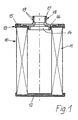
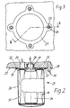
- FIG. 1 shows a longitudinal section through a Filter insert for a liquid filter in a simplified 2 shows the filter insert according to FIG. 1, built into a liquid filter on a reduced scale and in a simplified representation and as a longitudinal section II-II in Figure 3, and Figure 3 is a bottom view of the Liquid filter according to Figure 2;
- Figure 4 shows as partial longitudinal section of the filter insert in one line filters
- FIG. 1 shows a longitudinal section through a Filter insert 10 for a liquid filter in a simplified Representation of how it is used with fuel filters.
- the filter insert 10 has a hollow cylindrical design Filter element 11, which consists of a star-folded There is filter paper and its zigzag shape Edges in end plates 12, 13 made of plastic are tightly attached.
- the lower end plate 12 is closed and designed as a flat, circular plate, while the upper end plate 13 by a central Passage 14 is open.
- the star-shaped Filter element 11 is thus for a radial flow provided, this usually from the inside out happens.
- the star-shaped edges on the End faces of the filter element 11 are made of plastic cast in existing end plates 12 or 13, so that a tight and firm connection is created.
- the open end plate is 13 constructed in two parts and consists of one with the Filter element 11 connected outer ring 15 and one Inner part 16, which is rotationally symmetrical and has the central passage 14.
- the inner part 16 has a tubular protruding from the filter insert 10 to the outside Socket 17, which is a fir tree-shaped on its outer circumference Profile 18 has.
- This profile is here from two annular ribs 19 formed at a distance run from each other and close to the end of the nozzle 17 are arranged.
- This profile 18 now serves two functions, namely once as a connection means for attaching the Filter insert 10 in a not shown Connection module and also as a sealant for Internal seal in the liquid filter between one Dirt side and a clean side.
- the inner part 16 is simple, stable and inexpensive and can be built from same plastic as the outer ring 15. This can be advantageous against fuel resistant plastic, such as polyamide, use.
- fuel resistant plastic such as polyamide
- the fir tree-like profile 18 can be made of plastic relatively just shape it.
- FIG 2 now shows a simplified representation Longitudinal section through a liquid filter 21 in which the Filter insert 10 is installed according to Figure 1, the Filter insert 10 is shown on a smaller scale.
- the liquid filter 21 has a connection module 22, in which a first connection opening 23 for the inlet and a second connection opening 24 is formed for the drain are. Both connection openings 23, 24 are obvious together in a flat connection surface 25 of the Connection module 22.
- the second connection opening 24 for the The process is the same in diameter and depth trained that she the nozzle 17 with his fir tree-like profile 18 can accommodate appropriately.
- the Filter insert 10 can be easily axial Insert with its socket 17 into the second Install connection opening 24 quickly and easily. After Mounting the filter insert 10 on the connection module 22
- the nozzle 17 with its ribs 19 takes on both Holding function as well as a sealing function.
- the filter insert 10 is then a cup-shaped housing 26 covers, the housing 26 with an annular flange formed at its open end 27 abuts the connecting surface 25.
- On the ring flange 27 are four eyes 28 evenly distributed around the circumference trained on which the housing 26 by means of Screw connections 29 is attached to the connection module 22.
- An annular groove 31 is formed in the annular flange 27, the receives an O-ring 32 used for external sealing.
- the Connection openings 23 and 24 are of course within the area covered by the housing 26.
- the housing 26 is designed in its axial length so that the lower end plate 12 can be supported on the housing and thus an axial fixing of the filter insert 10 in Housing 26 takes place.
- FIG. 3 which is a bottom view of the liquid filter 21 according to FIG. 2, shows in more detail, become one Removal of the dirty filter insert 10 the four Loosened screw connections 29 and the housing 26 removed. Then the dirty filter insert 10 can quickly and simply pull it out by an axial movement and can be replaced by a new filter insert.
- the Liquid filter 21 with the interchangeable filter insert 10 thus leads to low waste since the filter insert 10 consists only of combustible material, such as polyamide and Filter paper, and is therefore thermally usable.
- FIG. 2 in connection with FIG. 3 shows in more detail, allows the design of the liquid filter 21 a simple and inexpensive construction of the housing 26.
- Das Housing 26 can be made of metal if necessary are produced, in which case the screw connections 29 a flawless, safe and tight attachment to the Allow connection module 22.
- the take over Screw connections 29 also a centering function for that Housing 26 so that the tubular socket 17 in its Holding function and its sealing function not impaired becomes.
- the filter insert 10 can be at the bottom of the support cup-shaped housing 26 so that it also in axial direction is set. It is also on demand easily possible, the housing 26 also made of plastic to produce, advantageously a polyamide with a Glass fiber reinforcement up to 25% is suitable.
- Plastic-made housing 26 can be attached in done in the same way via the screw connections 29; on the other hand, it is possible for a plastic housing 26 27 suitable suitable bores in the annular flange To be provided so that self-tapping for fastening Screws can be used.
- the operation of the liquid filter 21 is as follows explained:
- the fuel to be cleaned passes through the first connection opening 23 past the outer circumference of the upper, second end plate 13, on the dirty side 33 of the Liquid filter 21.
- the fuel flows through then the filter element 11 radially and arrives cleaned on the clean side 34.
- Via the passage 14 can the cleaned fuel to the second connection opening 24 in Drain connection module 22.
- the two ring-shaped extending ribs 19 in the fir tree-like profile 18 take over in addition to their function of the bracket Function of the seal, so that without an additional Component an inner seal between clean side 34 and Dirt side 33 takes place.
- FIG 4 now shows a simplified representation partial longitudinal section through a liquid filter 40, in which the filter insert 10 is installed according to Figure 1, wherein the filter insert 10 is shown on a smaller scale is.
- the liquid filter 40 is here as a line filter formed, which has a housing 41 made of aluminum and at a cover 42 and a cup-shaped housing part 43 are tightly and firmly connected.
- the two Connection piece 44 on the cover 42 and 45 on the housing part 43 are coaxial.
- the cover 42 takes over the function here of the connection module and for this purpose points to its Inside the matching connection opening 46, the coaxial to the connecting piece 44 and in which the filter insert 10 is inserted with its nozzle 17, which fir-tree-shaped profile 18 both the function of Bracket as well as the seal takes over.
- the embodiments shown are Changes possible without the idea of the invention notification departing.
- a circular design of the Filter insert 10 is particularly advantageous, can by axial assembly or disassembly of the filter insert 10 the tubular socket 17 also another Have a cross-sectional shape, for example square, rectangular or triangular or any other shape, if this is appropriate for the installation conditions.
- the number, shape and design of the ribs 19 in the fir-tree-like profile 18 can be part of the fulfilling holding and sealing functions vary.
- the design of the housing 26 and the fastening means 29 can be changed without departing from the spirit of the invention departing.
- the filter insert can also be used in others Housing filters, cartridge or box filters, line filters and also use in disposable filters, especially since it uses less Components and its handling is easier.
- the aluminum housing shown in Figure 4 also a sheet steel housing or Plastic are made.
- the housing can also do so be formed that the receiving opening for the nozzle the filter insert in the other part of the housing, e.g. B. in cup-shaped housing part is arranged.
Landscapes
- Chemical & Material Sciences (AREA)
- Chemical Kinetics & Catalysis (AREA)
- Filtration Of Liquid (AREA)
Abstract
Description
Claims (16)
- Filtereinsatz für ein Flüssigkeitsfilter für Kraftstoffe, mit einem im wesentlichen hohlzylindrisch ausgebildeten Filterelement, insbesondere aus sternförmig gefalteten Filtermaterial, welches Filterelement dichtend zwischen stirnseitigen Endscheiben angeordnet ist und von der zu filtrierenden Flüssigkeit radial zur Längsachse des Filtereinsatzes durchströmbar ist, wobei die eine erste Endscheibe geschlossen ausgebildet ist, während die andere zweite Endscheibe einen zentralen Durchgang aufweist, der durch einen nach außen ragenden rohrförmigen Stutzen verläuft, an dem Anschlussmittel zum Befestigen des Filtereinsatzes an einem Anschlussmodul sowie Dichtmittel zum inneren Abdichten zwischen einer Schmutz- und eine Reinseite angeordnet sind, dadurch gekennzeichnet, dass der Stutzen (17) an seinem Außenumfang ein die Funktionen der Anschlussmittel und der Dichtmittel übernehmendes, tannenbaumartiges Profil (18) mit Rippen (19) aufweist, wodurch der Filtereinsatz (10) mit seinem zentral angeordneten Stutzen (17) in Längsrichtung in eine Anschlussöffnung (24) eines Anschlussmoduls (22) einsteckbar ist.
- Filtereinsatz nach Anspruch 1, dadurch gekennzeichnet, dass die zweite Endscheibe (13) mit dem rohrförmigen Stutzen (17) aus Kunststoff, insbesondere Polyamid, besteht.
- Filtereinsatz nach Anspruch 1 oder 2, dadurch gekennzeichnet, dass die zweite Endscheibe (13) mit dem rohrförmigen Stutzen (17) kreisringförmig ausgebildet ist.
- Filter nach einem der Ansprüche 1 bis 3, dadurch gekennzeichnet, dass die zweite Endscheibe (13) ausschließlich die Innenabdichtung (19) zwischen Schmutz (23) und Reinseite (24) übernimmt.
- Filtereinsatz nach einem der Ansprüche 1 bis 4, dadurch gekennzeichnet, dass die erste Endscheibe (12) aus Kunststoff und das Filterelement (11) aus Filterpapier bestehen.
- Filtereinsatz nach einem oder mehreren der Ansprüche 1 bis 5, dadurch gekennzeichnet, dass die zweite Endscheibe (13) zweigliedrig aufgebaut ist und ein den Stutzen (17) mit dem Profil (18) aufweisendes, ringförmiges Innenteil (16) und einen damit fest verbundenen, das Filtermaterial (11) dicht und fest haltenden Außenring (15) aufweist, die beide aus Kunststoff bestehen.
- Filtereinsatz nach einem der Ansprüche 1 bis 6, dadurch gekennzeichnet, dass er mit seinem rohrförmigen Stutzen (17) in eine zugeordnete Anschlussöffnung (24) des Anschlussmoduls (22) ragt, wobei das Anschlussmodul (22) eine zusätzliche Anschlussöffnung (23) für den Zulauf aufweist und dass der Filtereinsatz (10) sowie die beiden Anschlussöffnungen (23, 24) im Anschlussmodul (22) von einem topfförmigen Gehäuse (26) überdeckt werden, das mit seinem am offenen Ende liegenden Rand (27) am Anschlussmodul (22) dicht befestigt ist.
- Filtereinsatz nach Anspruch 7, dadurch gekennzeichnet, dass sich der Filtereinsatz (10) mit seiner ersten Endkappe (12) innen am Gehäuse (26) abstützt.
- Filtereinsatz nach einem der Ansprüche 7 und 8, dadurch gekennzeichnet, dass das Gehäuse (26) insbesondere durch Schraubverbindungen (29) lösbar am Anschlussmodul (22) befestigt ist, wobei ein eingelegter Dichtring (32) die Abdichtung des Innenraums des Gehäuses (26) nach außen übernimmt.
- Filtereinrichtung nach einem der Ansprüche 7 bis 9, dadurch gekennzeichnet, dass das Anschlussmodul (22) eine im wesentlichen ebene Anbaufläche (25) aufweist, in welche die Anschlussöffnungen (23, 24) münden.
- Filtereinsatz nach einem der Ansprüche 7 bis 10, dadurch gekennzeichnet, dass der Flansch (27) des Gehäuses (26) eine den Dichtring (32) aufnehmende, umlaufende Ringnut (31) aufweist.
- Filtereinsatz nach einem der Ansprüche 7 bis 11, dadurch gekennzeichnet, dass das Gehäuse (26) mit Hilfe mehrerer, längs des Umfangs verteilter Schraubverbindungen (29) am Anschlussmodul (22) befestigt ist, wobei die Schraubverbindungen (29) das Gehäuse (26) relativ zum Anschlussmodul (22) zentrieren.
- Filtereinsatz nach einem der Ansprüche 1-6, dadurch gekennzeichnet, dass er mit seinem rohrförmigen Stutzen (17) in eine zugeordnete Anschlussöffnung (46) des Anschlussmoduls ragt, das als eines der Teile eines zweiteiligen Gehäuses (41) eines Leitungsfilters (40) ausgebildet ist.
- Filtereinsatz nach Anspruch 13, dadurch gekennzeichnet, dass als Anschlussmodul der Deckel (42) des Gehäuses (41) verwendet wird.
- Filtereinsatz nach Anspruch 13 oder 14, dadurch gekennzeichnet, dass die Anschlussstutzen (44, 45) am Deckel (42) und am becherförmigen Gehäuseteil (43) sowie der Stutzen (17) des Filtereinsatzes (10) und dessen zugeordnete Aufnahmeöffnung (46) koaxial zueinander angeordnet sind.
- Filtereinsatz nach einem der Ansprüche 13-15, dadurch gekennzeichnet, dass das Leitungsfilter als Wegwerffilter mit einem aus Kunststoff bestehenden Gehäuse ausgeführt ist.
Applications Claiming Priority (3)
| Application Number | Priority Date | Filing Date | Title |
|---|---|---|---|
| DE10003993 | 2000-01-29 | ||
| DE10003993A DE10003993A1 (de) | 2000-01-29 | 2000-01-29 | Filtereinsatz für ein Flüssigkeitsfilter |
| PCT/DE2000/004206 WO2001054791A1 (de) | 2000-01-29 | 2000-11-25 | Filtereinsatz für ein flüssigkeitsfilter |
Publications (2)
| Publication Number | Publication Date |
|---|---|
| EP1255604A1 EP1255604A1 (de) | 2002-11-13 |
| EP1255604B1 true EP1255604B1 (de) | 2003-11-05 |
Family
ID=7629225
Family Applications (1)
| Application Number | Title | Priority Date | Filing Date |
|---|---|---|---|
| EP00993806A Expired - Lifetime EP1255604B1 (de) | 2000-01-29 | 2000-11-25 | Filtereinsatz für ein flüssigkeitsfilter |
Country Status (5)
| Country | Link |
|---|---|
| EP (1) | EP1255604B1 (de) |
| JP (1) | JP2003520668A (de) |
| DE (2) | DE10003993A1 (de) |
| ES (1) | ES2210037T3 (de) |
| WO (1) | WO2001054791A1 (de) |
Families Citing this family (10)
| Publication number | Priority date | Publication date | Assignee | Title |
|---|---|---|---|---|
| DE102005008686B4 (de) * | 2005-02-25 | 2010-09-23 | Mann + Hummel Gmbh | Verfahren zur Herstellung von Fluid- oder Luftfiltern und damit hergestellte Filter |
| DE202007014821U1 (de) * | 2007-10-02 | 2009-02-26 | Mann+Hummel Gmbh | Filterelement V-Dichtung |
| DE202008004290U1 (de) | 2008-03-27 | 2009-08-06 | Mann+Hummel Gmbh | Filterverschluss-System |
| DE102008034904A1 (de) * | 2008-07-26 | 2010-01-28 | Mahle International Gmbh | Moduleinsatz zum Einbau in einen Flüssigkeitsfilter |
| BRPI1005768A2 (pt) * | 2010-12-23 | 2013-04-24 | Mahle Metal Leve Sa | filtro de combustÍvel |
| DE102012211185A1 (de) * | 2012-06-28 | 2014-01-02 | Robert Bosch Gmbh | Flüssigkeitsfilter mit Dämpfungselement, sowie Filtereinsatz für einen Flüssigkeitsfilter |
| DE102013201793A1 (de) | 2013-02-05 | 2014-08-07 | Robert Bosch Gmbh | Flüssigkeitsfilter |
| CN103982718B (zh) * | 2014-05-16 | 2017-01-11 | 江苏宇海环保设备有限公司 | 管连接件 |
| BR102014020222A2 (pt) * | 2014-08-14 | 2015-06-09 | Devocir Antônio Lira | Conector universal para filtro de combustível para máquinas agrícolas |
| DE102019127739A1 (de) * | 2019-10-15 | 2021-04-15 | Herding Gmbh Filtertechnik | Filterelement, Filterelementhalterung für ein Filterelement, eine Filtervorrichtung, und ein Verfahren zur Herstellung eines Filterelements |
Family Cites Families (26)
| Publication number | Priority date | Publication date | Assignee | Title |
|---|---|---|---|---|
| JPS4838738B1 (de) * | 1968-11-21 | 1973-11-19 | ||
| JPS474132Y1 (de) * | 1969-07-02 | 1972-02-14 | ||
| JPS5031995Y2 (de) * | 1971-11-12 | 1975-09-18 | ||
| JPS49118463A (de) * | 1973-03-13 | 1974-11-12 | ||
| JPS578886Y2 (de) * | 1977-04-30 | 1982-02-20 | ||
| EP0023548B1 (de) * | 1979-06-15 | 1984-02-08 | Sartorius GmbH. | Mehrteiliges Filtergehäuse zur Aufnahme von mehreren patronenförmigen Filterelementen |
| JPS6058214A (ja) * | 1983-09-07 | 1985-04-04 | Kubota Ltd | 沈降処理装置 |
| JPS60124575A (ja) * | 1983-12-08 | 1985-07-03 | Nissan Motor Co Ltd | 自動車のエンジンフ−ド構造 |
| JPS61111516A (ja) * | 1984-11-06 | 1986-05-29 | 松下電器産業株式会社 | 厚膜ハイブリツド電子部品 |
| JPH0636847B2 (ja) * | 1985-03-26 | 1994-05-18 | 本田技研工業株式会社 | 内燃機関用オイル濾過装置 |
| EP0231862B1 (de) * | 1986-01-27 | 1994-05-04 | Cuno Incorporated | Schnellwechselfilterpatrone und Kopf dafür |
| WO1988003431A1 (en) * | 1986-11-04 | 1988-05-19 | Eastman Kodak Company | Liquid filter apparatus |
| GB8703313D0 (en) * | 1987-02-13 | 1987-03-18 | Process Scient Innovations | Coupling |
| US4880536A (en) * | 1987-05-15 | 1989-11-14 | Pall Corporation | Filter assembly of a manifold, mounting ring and filter housing |
| GB2222534B (en) * | 1988-09-09 | 1992-11-25 | Process Scient Innovations | Filter assembly and cartridge therefor |
| DE4222136A1 (de) * | 1992-07-06 | 1994-01-13 | Bosch Gmbh Robert | Flüssigkeitsfilter |
| US5766462A (en) * | 1993-12-01 | 1998-06-16 | Golview Pty Ltd | Water treatment apparatus |
| FI98990C (fi) * | 1995-10-27 | 1997-09-25 | Parker Hannifinn Oy | Suodatin |
| DE19548864A1 (de) * | 1995-12-27 | 1997-07-03 | Knecht Filterwerke Gmbh | Ringfiltereinsatz |
| DE19604371A1 (de) * | 1996-02-07 | 1997-08-14 | Bosch Gmbh Robert | Filtereinsatz für einen Flüssigkeitsfilter |
| DE19634717A1 (de) * | 1996-08-28 | 1998-03-05 | Bosch Gmbh Robert | Filtereinrichtung für eine Kraftstoffördereinheit |
| DE19717324A1 (de) * | 1996-09-04 | 1998-03-05 | Volkswagen Ag | Verbindungsanordnung für eine Kraftstoffleitung |
| DE19644647A1 (de) * | 1996-10-26 | 1998-04-30 | Mann & Hummel Filter | Flüssigkeitsfilter |
| DE19801349A1 (de) * | 1997-01-17 | 1998-08-27 | Paul Couwenbergs | Hauptfilter für ein Aggregat, wie einen Motor, und Aggregat mit einem Hauptfilter |
| US5891334A (en) * | 1997-06-19 | 1999-04-06 | Plymouth Products, Inc. | Filter cartridge retaining assembly |
| WO2000004973A1 (en) * | 1998-07-22 | 2000-02-03 | Pall Corporation | Filter assemblies |
-
2000
- 2000-01-29 DE DE10003993A patent/DE10003993A1/de not_active Withdrawn
- 2000-11-25 JP JP2001554768A patent/JP2003520668A/ja active Pending
- 2000-11-25 EP EP00993806A patent/EP1255604B1/de not_active Expired - Lifetime
- 2000-11-25 ES ES00993806T patent/ES2210037T3/es not_active Expired - Lifetime
- 2000-11-25 DE DE50004377T patent/DE50004377D1/de not_active Expired - Lifetime
- 2000-11-25 WO PCT/DE2000/004206 patent/WO2001054791A1/de not_active Ceased
Also Published As
| Publication number | Publication date |
|---|---|
| JP2003520668A (ja) | 2003-07-08 |
| EP1255604A1 (de) | 2002-11-13 |
| WO2001054791A1 (de) | 2001-08-02 |
| DE10003993A1 (de) | 2001-08-23 |
| DE50004377D1 (de) | 2003-12-11 |
| ES2210037T3 (es) | 2004-07-01 |
Similar Documents
| Publication | Publication Date | Title |
|---|---|---|
| EP0692292B2 (de) | Flüssigkeitsfilter | |
| EP1144078B1 (de) | Rundfilterpatrone | |
| EP0951329B1 (de) | Filter, insbesondere für das schmieröl einer brennkraftmaschine | |
| EP0702144B1 (de) | Wechselfilterelement zum Reinigen von Kraftstoff und Filtergehäuse zum Einbau des Wechselfilterelements | |
| DE2843641A1 (de) | Wasserfilter, insbesondere fuer aquariumwasser | |
| DE102010027150B4 (de) | Filterelement und Filtermodul | |
| EP0723796A1 (de) | Flüssigkeitsfilter | |
| EP1233173A2 (de) | Filterelement für Kraftstoffe | |
| DE19538883A1 (de) | Filter für Flüssigkeiten, insbesondere Dieselkraftstoff | |
| DE102009041298A1 (de) | Kraftstofffilter einer Brennkraftmaschine | |
| EP2762219A1 (de) | Becherförmiges Gehäuse, Vorrichtung zum Abscheiden von Flüssigkeit aus Luft sowie Verfahren zur Montage des becherförmigen Gehäuses auf einen Nippel | |
| EP1255604B1 (de) | Filtereinsatz für ein flüssigkeitsfilter | |
| DE69614887T2 (de) | Filter | |
| EP1690581B1 (de) | Flüssigkeitsfiltersystem | |
| DE102019004926B3 (de) | Fluidfilter für einen Kraftwagen und Filterkartusche für einen solchen Fluidfilter | |
| DE202005010445U1 (de) | Filteranordnung für Flüssigkeiten | |
| DE2621888B2 (de) | Stroemungsfilter | |
| DE19859960B4 (de) | Flüssigkeitsfilter | |
| DE102008055518A1 (de) | Verbindungsstück | |
| DE3514778C1 (de) | Filtereinsatz für einen Flüssigkeitsfilter | |
| DE69206212T2 (de) | Wegwerf-Ölfilter. | |
| DE69824056T2 (de) | Fluidfilteranordnung | |
| EP0589377B1 (de) | Filter zum Reinigen von Kraftstoff | |
| EP3727643B1 (de) | Filterelement eines filters für flüssigkeit und filter | |
| EP2125141A1 (de) | Filterelement zur abreinigung von fluiden |
Legal Events
| Date | Code | Title | Description |
|---|---|---|---|
| PUAI | Public reference made under article 153(3) epc to a published international application that has entered the european phase |
Free format text: ORIGINAL CODE: 0009012 |
|
| 17P | Request for examination filed |
Effective date: 20020829 |
|
| AK | Designated contracting states |
Kind code of ref document: A1 Designated state(s): AT BE CH CY DE DK ES FI FR GB GR IE IT LI LU MC NL PT SE TR |
|
| RIN1 | Information on inventor provided before grant (corrected) |
Inventor name: ZORZIN, LUCIANO Inventor name: KAEHLER, JUERGEN Inventor name: TORREMOCHA, EUGENIO FERNANDEZ Inventor name: BAZ, ALFONSO Inventor name: LOPEZ, RAFAEL |
|
| GRAH | Despatch of communication of intention to grant a patent |
Free format text: ORIGINAL CODE: EPIDOS IGRA |
|
| GRAS | Grant fee paid |
Free format text: ORIGINAL CODE: EPIDOSNIGR3 |
|
| GRAA | (expected) grant |
Free format text: ORIGINAL CODE: 0009210 |
|
| AK | Designated contracting states |
Kind code of ref document: B1 Designated state(s): DE ES FR GB IT |
|
| REG | Reference to a national code |
Ref country code: GB Ref legal event code: FG4D Free format text: NOT ENGLISH |
|
| REF | Corresponds to: |
Ref document number: 50004377 Country of ref document: DE Date of ref document: 20031211 Kind code of ref document: P |
|
| REG | Reference to a national code |
Ref country code: IE Ref legal event code: FG4D Free format text: GERMAN |
|
| GBT | Gb: translation of ep patent filed (gb section 77(6)(a)/1977) |
Effective date: 20040118 |
|
| REG | Reference to a national code |
Ref country code: IE Ref legal event code: FD4D |
|
| REG | Reference to a national code |
Ref country code: ES Ref legal event code: FG2A Ref document number: 2210037 Country of ref document: ES Kind code of ref document: T3 |
|
| ET | Fr: translation filed | ||
| PLBE | No opposition filed within time limit |
Free format text: ORIGINAL CODE: 0009261 |
|
| STAA | Information on the status of an ep patent application or granted ep patent |
Free format text: STATUS: NO OPPOSITION FILED WITHIN TIME LIMIT |
|
| 26N | No opposition filed |
Effective date: 20040806 |
|
| PGFP | Annual fee paid to national office [announced via postgrant information from national office to epo] |
Ref country code: ES Payment date: 20091123 Year of fee payment: 10 |
|
| PGFP | Annual fee paid to national office [announced via postgrant information from national office to epo] |
Ref country code: GB Payment date: 20091123 Year of fee payment: 10 |
|
| GBPC | Gb: european patent ceased through non-payment of renewal fee |
Effective date: 20101125 |
|
| PG25 | Lapsed in a contracting state [announced via postgrant information from national office to epo] |
Ref country code: GB Free format text: LAPSE BECAUSE OF NON-PAYMENT OF DUE FEES Effective date: 20101125 |
|
| REG | Reference to a national code |
Ref country code: ES Ref legal event code: FD2A Effective date: 20120110 |
|
| PG25 | Lapsed in a contracting state [announced via postgrant information from national office to epo] |
Ref country code: ES Free format text: LAPSE BECAUSE OF NON-PAYMENT OF DUE FEES Effective date: 20101126 |
|
| REG | Reference to a national code |
Ref country code: FR Ref legal event code: PLFP Year of fee payment: 16 |
|
| REG | Reference to a national code |
Ref country code: FR Ref legal event code: PLFP Year of fee payment: 17 |
|
| REG | Reference to a national code |
Ref country code: FR Ref legal event code: PLFP Year of fee payment: 18 |
|
| PGFP | Annual fee paid to national office [announced via postgrant information from national office to epo] |
Ref country code: IT Payment date: 20191120 Year of fee payment: 20 Ref country code: FR Payment date: 20191121 Year of fee payment: 20 |
|
| PGFP | Annual fee paid to national office [announced via postgrant information from national office to epo] |
Ref country code: DE Payment date: 20200124 Year of fee payment: 20 |