EP1255657B1 - Verfahren zur trennung von kraftstoffdampf-luft-gemischen und vorrichtung zur durchführung dieses verfahrens - Google Patents
Verfahren zur trennung von kraftstoffdampf-luft-gemischen und vorrichtung zur durchführung dieses verfahrens Download PDFInfo
- Publication number
- EP1255657B1 EP1255657B1 EP01907536A EP01907536A EP1255657B1 EP 1255657 B1 EP1255657 B1 EP 1255657B1 EP 01907536 A EP01907536 A EP 01907536A EP 01907536 A EP01907536 A EP 01907536A EP 1255657 B1 EP1255657 B1 EP 1255657B1
- Authority
- EP
- European Patent Office
- Prior art keywords
- preseparator
- fuel tank
- gas
- filter
- fuel
- Prior art date
- Legal status (The legal status is an assumption and is not a legal conclusion. Google has not performed a legal analysis and makes no representation as to the accuracy of the status listed.)
- Expired - Lifetime
Links
Images


Classifications
-
- B—PERFORMING OPERATIONS; TRANSPORTING
- B60—VEHICLES IN GENERAL
- B60K—ARRANGEMENT OR MOUNTING OF PROPULSION UNITS OR OF TRANSMISSIONS IN VEHICLES; ARRANGEMENT OR MOUNTING OF PLURAL DIVERSE PRIME-MOVERS IN VEHICLES; AUXILIARY DRIVES FOR VEHICLES; INSTRUMENTATION OR DASHBOARDS FOR VEHICLES; ARRANGEMENTS IN CONNECTION WITH COOLING, AIR INTAKE, GAS EXHAUST OR FUEL SUPPLY OF PROPULSION UNITS IN VEHICLES
- B60K15/00—Arrangement in connection with fuel supply of combustion engines or other fuel consuming energy converters, e.g. fuel cells; Mounting or construction of fuel tanks
- B60K15/03—Fuel tanks
- B60K15/035—Fuel tanks characterised by venting means
- B60K15/03504—Fuel tanks characterised by venting means adapted to avoid loss of fuel or fuel vapour, e.g. with vapour recovery systems
-
- B—PERFORMING OPERATIONS; TRANSPORTING
- B01—PHYSICAL OR CHEMICAL PROCESSES OR APPARATUS IN GENERAL
- B01D—SEPARATION
- B01D17/00—Separation of liquids, not provided for elsewhere, e.g. by thermal diffusion
- B01D17/02—Separation of non-miscible liquids
- B01D17/0217—Separation of non-miscible liquids by centrifugal force
-
- F—MECHANICAL ENGINEERING; LIGHTING; HEATING; WEAPONS; BLASTING
- F02—COMBUSTION ENGINES; HOT-GAS OR COMBUSTION-PRODUCT ENGINE PLANTS
- F02M—SUPPLYING COMBUSTION ENGINES IN GENERAL WITH COMBUSTIBLE MIXTURES OR CONSTITUENTS THEREOF
- F02M25/00—Engine-pertinent apparatus for adding non-fuel substances or small quantities of secondary fuel to combustion-air, main fuel or fuel-air mixture
- F02M25/08—Engine-pertinent apparatus for adding non-fuel substances or small quantities of secondary fuel to combustion-air, main fuel or fuel-air mixture adding fuel vapours drawn from engine fuel reservoir
-
- Y—GENERAL TAGGING OF NEW TECHNOLOGICAL DEVELOPMENTS; GENERAL TAGGING OF CROSS-SECTIONAL TECHNOLOGIES SPANNING OVER SEVERAL SECTIONS OF THE IPC; TECHNICAL SUBJECTS COVERED BY FORMER USPC CROSS-REFERENCE ART COLLECTIONS [XRACs] AND DIGESTS
- Y02—TECHNOLOGIES OR APPLICATIONS FOR MITIGATION OR ADAPTATION AGAINST CLIMATE CHANGE
- Y02C—CAPTURE, STORAGE, SEQUESTRATION OR DISPOSAL OF GREENHOUSE GASES [GHG]
- Y02C20/00—Capture or disposal of greenhouse gases
- Y02C20/40—Capture or disposal of greenhouse gases of CO2
Definitions
- the present invention relates to a method for Separation of fuel vapor and air mixtures into its components and an apparatus for performing this method.
- the method is particularly suitable for cleaning of vapor mixtures, such as those found in fuel tanks Motor vehicles arise.
- the invention is therefore based on the object of a method for cleaning of fuel vapor-air mixtures, and a device for Implementation of the procedure with which to create complex and large filters can be avoided.
- the separation of the fuel components is achieved not through adsorption as before, but through physical Separation by condensing the hydrocarbons in the pre-separator. Furthermore, the amount to be discharged from the tank system is reduced Gas mass flow around the separated steam mass flow, so that the tank pressure and thus the line cross-sections be reduced, which improves the refuelability.
- the gases are compressed first and then fed to a capacitor, on the condensation surfaces Conversion of hydrocarbons to the liquid phase.
- the condensation surfaces of the capacitor can be used for this own cooling circuit. There is no separate cooling circuit required if the condensing surfaces of the capacitor match the Air conditioning are connected. But it is also the use of semiconductor cooling elements conceivable.
- the one forming the pre-separator Compressor and condenser combined into one unit.
- the compressed gas mixture has only a short way to the condenser, which significantly reduces pressure losses and the compressor can be made relatively small.
- the pre-separator is around a nozzle or expanded a valve as a throttle and a cyclone.
- a post-condensation takes place.
- the centrifugal force separates condensate and fed back into the fuel tank via a connection.
- the cleaned gas has a degree of purity, which is a further reduction of a downstream activated carbon filter or possibly made possible by a catalytic burner. In certain circumstances you can even do without an activated carbon filter and instead arrange a gas separation membrane before the gas is released into the atmosphere.
- the pre-separator to integrate into the fuel tank. Since all connection points the device according to the invention in the fuel tank are arranged, these points of increased permeation in the Construction no longer considered, which is an additional simplification is and thus leads to a further cost reduction. About that are also eliminated due to the compact design of the pre-separator long hose connections.
- a second embodiment of the method according to the invention condenses the accumulated during operation or refueling Gas without prior compression in a mixing condenser. This will the mixture passed into a container containing a liquid cooling medium is filled. Fuel can preferably be used as the cooling medium become. Upon contact with the cool liquid, the hydrocarbons condense, while the cleaned gas through an outlet in the upper Part of the mixing capacitor is fed to a filter. The condensed Components are then returned to the fuel tank fed.
- cooling medium to cool.
- One possibility is cooling the walls of the condenser.
- semiconductor cooling elements can be installed in the capacitor Arrange.
- the capacitor is connected to one Cooling circuit connected.
- the mixed capacitor draining liquid is fed to a cooler before it is clear with a lower temperature is fed back to the mixing condenser.
- cooling tubes can be arranged in the mixing condenser, through which a coolant flows. This cooler can be a separate cooler, which is operated via the vehicle's air conditioning system becomes.
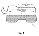
- the fuel tank 1 of a motor vehicle shown in FIG. 1 is Can be filled via a filler neck 2.
- vent lines 3a, 3b for ventilation during refueling and the operation are vent lines 3a, 3b in the upper area of the fuel tank 1 arranged. These vent lines open into the expansion tank with internal pre-isolator 4.
- the gas collected via the vent lines 3a, 3b is the Pre-separator 4 supplied, the hydrocarbons contained in the gas condense.
- the cleaned gas is then one Activated carbon filter 5 supplied before it is in a second cleaning small activated carbon filter is led to the atmosphere.
- the in Pre-separator 4 condensed hydrocarbons via a Outlet 6 fed back to the fuel tank.
- the pre-separator 4 in Figure 2 has a compression stage 7 in which the gas supplied via the vent lines 3a, 3b compresses and is heated. The compressed gas then flows into a condenser 8. At its condensation surface 9, the condense in the gas mixture contained hydrocarbons. The liquid phase collects itself at the bottom of the capacitor 8 and is via a valve 10 in the Fuel tank 1 passed. Via a membrane 11, on the other hydrocarbons the gas is separated by means of a nozzle 12 expands. There are liquid drops in the now accelerated gas flow, entering a cyclone 13. Because of the centrifugal force fuel drops separate on the wall of the cyclone 13. While the liquid phase is returned to the fuel tank 1, the now cleaned gas mixture reaches via connection 14 Activated carbon filter 5 arranged outside the fuel tank 1.
- the device shown in Figure 3 shows a section of a fuel tank 1 with a bubble tank inside the upper area 16.
- the vent lines extending into the bubble tank 16 3a, 3b are there with a mixing capacitor 17 to the lower edge of a Overflow opening 18 filled with a cooling medium 19.
- the feed openings 20a, 20b of the ventilation lines 3a, 3b are in the bottom area of the Mixing capacitor 17 arranged.
- Via a cooling circuit 21 Condition of constant temperature in the mixing condenser 17 reached. To is with constant mass flow of cooling medium from the mixing condenser 17 removed and fed to a heat exchanger. Then will the cooling medium cooled down in this way is fed back to the mixing condenser 17.
- the fuel 19 condensed into the cooling medium passes through the Overflow 18 on the mixing condenser 17 in the bubble tank 16. Die in its bottom area arranged pump 22 promotes the resulting Fuel 19 in the fuel tank 1, the delivery unit or the pump back.
- the rest in the upper region of the mixing capacitor 17 itself still accumulating gas mixture is passed to the activated carbon filter 5, wherein a sieve 23 in the area of the mixed condenser outlet ensures that no liquid components can reach the activated carbon filter 5.
Landscapes
- Engineering & Computer Science (AREA)
- Chemical & Material Sciences (AREA)
- Life Sciences & Earth Sciences (AREA)
- Sustainable Development (AREA)
- Sustainable Energy (AREA)
- Combustion & Propulsion (AREA)
- Transportation (AREA)
- Mechanical Engineering (AREA)
- Physics & Mathematics (AREA)
- Thermal Sciences (AREA)
- Chemical Kinetics & Catalysis (AREA)
- Cooling, Air Intake And Gas Exhaust, And Fuel Tank Arrangements In Propulsion Units (AREA)
- Supplying Secondary Fuel Or The Like To Fuel, Air Or Fuel-Air Mixtures (AREA)
- Separation Using Semi-Permeable Membranes (AREA)
- Vaporization, Distillation, Condensation, Sublimation, And Cold Traps (AREA)
- Hydrogen, Water And Hydrids (AREA)
Description
- Figur 1:
- eine schematische Darstellung der erfindungsgemäßen Vorrichtung,
- Figur 2:
- einen Vorabscheider mit Kompressions- und Kondensationsstufe,
- Figur 3:
- einen Vorabscheider mit Mischkondensator.
Claims (27)
- Verfahren zur Trennung von Kraftstoffdampf-Luft-Gemischen eines Kraftstoffbehälters (1), vorzugsweise in Kraftfahrzeugen, bei dem das zu reinigende Gasgemisch aus dem Kraftstoffbehälter (1) einem Filter (5) zugeführt wird, wobei das zu reinigende Gasgemisch einem Vorabscheider (4) zugeführt wird und in dem Vorabscheider (4) Kohlenwasserstoffe aus dem Gasgemisch abgeschieden und dem Kraftstoffbehälter (1) wieder zugeführt werden und wobei das gereinigte Gas zum Filter (5) geleitet wird, dadurch gekennzeichnet, dass das Abscheiden der Kohlenwasserstoffe in dem Vorabscheider (4) im Inneren des Kraftstoffbehälters (1) erfolgt und dass das von dem Vorabscheider (4) gereinigte Gas dem Kraftstoffbehälter (1) entnommen wird.
- Verfahren nach Anspruch 1, dadurch gekennzeichnet, dass das Gasgemisch aus dem Kraftstoffbehälter (1) über Entlüftungsleitungen (3a, 3b)dem Vorabscheider (4) zugeführt wird.
- Verfahren nach Anspruch 1 und 2, dadurch gekennzeichnet, dass in dem Gasgemisch enthaltene Kohlenwasserstoffe in dem Vorabscheider (4) kondensiert werden.
- Verfahren nach Anspruch 3, dadurch gekennzeichnet, dass das Gasgemisch in dem Vorabscheider (4) vor der Kondensation komprimiert wird.
- Verfahren nach Anspruch 4, dadurch gekennzeichnet, dass das Gas nach der Kondensation expandiert wird.
- Verfahren nach Anspruch 5, dadurch gekennzeichnet, dass das Gas in einem zweiten Schritt nachkondensiert wird.
- Verfahren nach einem der Ansprüche 3 bis 6, dadurch gekennzeichnet, dass das Gas nach der Kondensation durch ein Filter, vorzugsweise eine Gastrennmembran, geleitet wird.
- Verfahren nach einem der Ansprüche 6 oder 7, dadurch gekennzeichnet, dass die in der Nachkondensation abgeschiedenen flüssigen Kohlenwasserstoffe in den Kraftstoffbehälter (1) geleitet werden.
- Verfahren nach einem der Ansprüche 3 bis 8, dadurch gekennzeichnet, dass das Gas zur Kondensation durch ein Kühlmedium, vorzugsweise Kraftstoff, geleitet wird.
- Verfahren nach einem der Ansprüche 3 bis 9, dadurch gekennzeichnet, dass die Kondensationsflächen (9) und das Kühlmedium gekühlt werden.
- Vorrichtung zur Durchführung des Verfahrens nach Anspruch 1 mit einem Kraftstoffbehälter (1), einem Filter (5), einem Vorabscheider (4) und einer Leitung von dem Vorabscheider (4) zum Filter, wobei im Kraftstoffbehälter (1) entstehende Gase dem Vorabscheider (4) zuführbar sind und der Vorabscheider (4) eine weitere Verbindung mit dem Kraftstoffbehälter (1) aufweist, dadurch gekennzeichnet, dass der Vorabscheider (4) im Inneren des Kraftstoffbehälters (1), vorzugsweise in dessen oberen Bereich, angeordnet ist.
- Vorrichtung nach Anspruch 11, dadurch gekennzeichnet, dass der Vorabscheider (4) mit Entlüftungsleitungen (3a, 3b) des Kraftstoffbehälters (1) zur Zuführung des Gases verbunden ist.
- Vorrichtung nach Anspruch 11 und 12, dadurch gekennzeichnet, dass der Vorabscheider (4) aus einer Kompressionsstufe (7) und einen Kondensationsflächen (9) aufweisenden Kondensator (8) gebildet ist.
- Vorrichtung nach einem der Ansprüche 11 bis 13, dadurch gekennzeichnet, dass in Strömungsrichtung nach den Kondensationsflächen (9) ein Filter (11), vorzugsweise eine Gastrennmembran angeordnet ist.
- Vorrichtung nach zumindest einem der Ansprüche 11 bis 14, dadurch gekennzeichnet, dass am strömungsseitigen Ausgang des Kondensators (8) eine Drossel (12) angeordnet ist.
- Vorrichtung nach Anspruch 15, dadurch gekennzeichnet, dass die Drossel (12) ein Ventil oder eine Düse ist.
- Vorrichtung nach zumindest einem der Ansprüche 11 bis 16, dadurch gekennzeichnet, dass nach dem Kondensator (8) ein weiterer Kondensator (13), vorzugsweise ein Zyklon angeordnet ist.
- Vorrichtung nach zumindest einem der Ansprüche 11 bis 17, dadurch gekennzeichnet, dass der weitere Kondensator (13) eine Verbindung mit dem Kraftstoffbehälter (1) zum Ableiten flüssiger Kohlenwasserstoffe besitzt.
- Vorrichtung nach den Ansprüchen 11 und 12, dadurch gekennzeichnet, dass der Vorabscheider (4) ein mit Kühlmedien (19), vorzugsweise Kraftstoff gefüllter Mischkondensator (17) ist.
- Vorrichtung nach Anspruch 19, dadurch gekennzeichnet, dass die Entlüftungsleitungen (3a, 3b) im unteren Bereich des Mischkondensators (17) enden.
- Vorrichtung nach zumindest einem der Ansprüche 19 und 20, dadurch gekennzeichnet, dass am Ausgang des Mischkondensators (17) zum Filter (5) ein Sieb (23) mit einer tropfenundurchlässigen Maschenweite angeordnet ist.
- Vorrichtung nach zumindest einem der Ansprüche 19 bis 21, dadurch gekennzeichnet, dass der Mischkondensator (17) in einem Ausperlbehälter (16) angeordnet ist.
- Vorrichtung nach Anspruch 22, dadurch gekennzeichnet, dass der Mischkondensator (17) einen Überlauf (18) in den Ausperlbehälter (16) besitzt.
- Vorrichtung nach zumindest einem der Ansprüche 11 bis 23, dadurch gekennzeichnet, dass an den Kondensationsflächen (9), am Mischkondensator (17) oder in dem Kühlmedium (19) Halbleiter-Kühlelemente angeordnet sind.
- Vorrichtung nach zumindest einem der Ansprüche 11 bis 23, dadurch gekennzeichnet, dass die Kondensationsflächen (9), der Mischkondensator (17) oder das Kühlmedium (19) mittels eines Kühlkreislaufes, vorzugsweise einer Klimaanlage kühlbar sind.
- Vorrichtung nach zumindest einem der Ansprüche 11 bis 25, dadurch gekennzeichnet, dass das Filter (5) ein Aktivkohlefilter oder eine Gastrennmembran ist.
- Vorrichtung nach zumindest einem der Ansprüche 11 bis 26, dadurch gekennzeichnet, dass in der weiteren Verbindung (6) ein Ventil (10) oder eine Pumpe (23), vorzugsweise eine Saugstrahlpumpe angeordnet ist.
Applications Claiming Priority (3)
| Application Number | Priority Date | Filing Date | Title |
|---|---|---|---|
| DE10007522 | 2000-02-18 | ||
| DE10007522A DE10007522B4 (de) | 2000-02-18 | 2000-02-18 | Verfahren zur Trennung von Kraftstoffdampf-Luft-Gemischen und Vorrichtung zur Durchführung dieses Verfahrens |
| PCT/EP2001/001645 WO2001060648A1 (de) | 2000-02-18 | 2001-02-15 | Verfahren zur trennung von kraftstoffdampf-luft-gemischen und vorrichtung zur durchführung dieses verfahrens |
Publications (2)
| Publication Number | Publication Date |
|---|---|
| EP1255657A1 EP1255657A1 (de) | 2002-11-13 |
| EP1255657B1 true EP1255657B1 (de) | 2003-07-16 |
Family
ID=7631495
Family Applications (1)
| Application Number | Title | Priority Date | Filing Date |
|---|---|---|---|
| EP01907536A Expired - Lifetime EP1255657B1 (de) | 2000-02-18 | 2001-02-15 | Verfahren zur trennung von kraftstoffdampf-luft-gemischen und vorrichtung zur durchführung dieses verfahrens |
Country Status (10)
| Country | Link |
|---|---|
| US (1) | US6878185B2 (de) |
| EP (1) | EP1255657B1 (de) |
| JP (1) | JP2003524732A (de) |
| KR (1) | KR100518089B1 (de) |
| AT (1) | ATE245097T1 (de) |
| AU (1) | AU2001235477A1 (de) |
| BR (1) | BR0108488A (de) |
| DE (2) | DE10007522B4 (de) |
| ES (1) | ES2203594T3 (de) |
| WO (1) | WO2001060648A1 (de) |
Families Citing this family (12)
| Publication number | Priority date | Publication date | Assignee | Title |
|---|---|---|---|---|
| DE10064592C2 (de) * | 2000-12-22 | 2003-12-11 | Siemens Ag | Entlüftungseinrichtung |
| DE10229758A1 (de) * | 2002-07-03 | 2004-01-29 | Daimlerchrysler Ag | Kraftstoffkondensationssystem |
| US7901191B1 (en) | 2005-04-07 | 2011-03-08 | Parker Hannifan Corporation | Enclosure with fluid inducement chamber |
| WO2006133465A1 (de) * | 2005-06-17 | 2006-12-21 | Exess Engineering Ges.M.B.H. | Einrichtung zur abscheidung von benzindämpfen |
| US7938871B2 (en) * | 2009-02-27 | 2011-05-10 | Nissan North America, Inc. | Vehicle filter assembly |
| KR101403083B1 (ko) * | 2009-08-24 | 2014-06-03 | 현대중공업 주식회사 | 에어 이젝터를 이용한 휴대용 싸이클론 집진기 |
| DE102010055320A1 (de) | 2010-12-21 | 2012-06-21 | Audi Ag | Kraftstoffsystem |
| US9739243B2 (en) * | 2012-02-10 | 2017-08-22 | Ford Gloabl Technologies, LLC | Methods and systems for fuel vapor control |
| DE102013216957B4 (de) | 2012-08-27 | 2021-12-30 | Robert Bosch Gmbh | Dieselkraftstoffpumpenmodul und Verfahren zum Betrieb einer Strahlpumpe |
| DE102014015941A1 (de) | 2013-11-20 | 2015-05-21 | Mann + Hummel Gmbh | Tankbelüftungsfilter mit Fallrohr |
| BE1030656B1 (fr) * | 2022-06-22 | 2024-01-30 | Plastic Omnium Advanced Innovation & Res | Système à carburant pour véhicule à moteur thermique |
| CN121630609A (zh) * | 2024-09-09 | 2026-03-10 | 通用汽车环球科技运作有限责任公司 | 蒸发排放物控制系统 |
Family Cites Families (27)
| Publication number | Priority date | Publication date | Assignee | Title |
|---|---|---|---|---|
| US2562839A (en) * | 1946-07-10 | 1951-07-31 | Gen Foods Corp | Filter unit for cookers |
| DE1046948B (de) * | 1956-12-31 | 1958-12-18 | Hoeschle Adolf Fa | Einrichtung zur Ausscheidung grober Brennstoffteilchen |
| US3815327A (en) * | 1972-09-15 | 1974-06-11 | C Viland | Method and apparatus for preventing loss of hydrocarbons to atmosphere |
| DE2421938A1 (de) * | 1974-05-07 | 1975-11-20 | Volkswagenwerk Ag | Anordnung zur fernhaltung von wasser aus einer kraftstoffanlage |
| US3913633A (en) * | 1974-10-21 | 1975-10-21 | Weil Mclain Company Inc | Liquid dispensing and vapor recovery system |
| JPS61257322A (ja) * | 1985-05-07 | 1986-11-14 | Nissan Motor Co Ltd | 燃料タンク用蒸発損失防止装置 |
| US4829968A (en) * | 1987-01-27 | 1989-05-16 | Onufer George R | Mobile fuel tank vapor emission control system and method |
| FR2630029B1 (fr) * | 1988-04-19 | 1991-05-24 | France Grignotage Sarl | Dispositif pour l'aspiration, le captage et le piegeage des vapeurs au-dessus des appareils de cuisson a l'eau ou a l'huile |
| DE4004500A1 (de) * | 1990-02-14 | 1991-08-22 | Daimler Benz Ag | Auffang- und sammeleinrichtung von kraftstoffdaempfen in kraftstoffanlagen |
| PL167652B1 (pl) * | 1990-02-27 | 1995-10-31 | Orbital Eng Pty | Instalacja do wielocylindrowego silnika spalinowego PL PL |
| US5301721A (en) * | 1990-05-24 | 1994-04-12 | Hartmann John P | Underground secondary containment and vapor recovery piping system |
| JP3158698B2 (ja) * | 1992-08-28 | 2001-04-23 | トヨタ自動車株式会社 | 蒸発燃料排出抑止装置 |
| US5255735A (en) * | 1992-12-21 | 1993-10-26 | Ford Motor Company | Fuel vapor recovery device |
| FR2700506B1 (fr) * | 1993-01-19 | 1995-03-10 | Siemens Automotive Sa | Dispositif de récupération de vapeurs issues d'un réservoir de carburant de véhicule automobile. |
| FR2724603B1 (fr) | 1994-09-16 | 1997-01-17 | Renault | Dispositif de controle de l'evaporation du carburant contenu dans un reservoir |
| FR2728200A1 (fr) | 1994-12-19 | 1996-06-21 | Peugeot | Dispositif de limitation de remplissage d'un reservoir de carburant et vehicule automobile equipe d'un tel dispositif |
| WO1996028316A1 (de) * | 1995-03-13 | 1996-09-19 | Fritz Curtius | Vermeidung von flüssigen emissionen aus fahrzeugen |
| JPH0932670A (ja) * | 1995-07-25 | 1997-02-04 | Honda Motor Co Ltd | 蒸発燃料制御弁 |
| US5738710A (en) * | 1995-08-08 | 1998-04-14 | Morikawa Industries Corporation | Control method and apparatus for material adsorbed on adsorbent, and solvent recovering method and apparatus using same |
| US5901689A (en) * | 1996-01-22 | 1999-05-11 | Mitsubishi Jidosha Kogyo Kabushiki Kaisha | Fuel tank device |
| DE19628583A1 (de) * | 1996-03-09 | 1998-01-22 | Fritz Curtius | Vermeidung von flüssigen Emissionen aus Fahrzeugen |
| DE19632690A1 (de) * | 1996-08-14 | 1998-02-19 | Reum Ag | Entlüftungsventil |
| JPH1193784A (ja) * | 1997-09-18 | 1999-04-06 | Nok Corp | 燃料蒸気回収装置 |
| EP0936097A1 (de) * | 1998-02-17 | 1999-08-18 | Imra Europe S.A. | Einrichtung zum Rückführen von Benzindämpfen in einem Kraftstoffbehälter und Verfahren zu ihrer Anwendung |
| JP3646217B2 (ja) * | 1999-07-08 | 2005-05-11 | 愛三工業株式会社 | キャニスタモジュール |
| US6599350B1 (en) * | 1999-12-20 | 2003-07-29 | Hi-Stat Manufacturing Company, Inc. | Filtration device for use with a fuel vapor recovery system |
| US6390074B1 (en) * | 2000-05-12 | 2002-05-21 | Ford Global Technologies, Inc. | Fuel assembly |
-
2000
- 2000-02-18 DE DE10007522A patent/DE10007522B4/de not_active Expired - Fee Related
-
2001
- 2001-02-15 JP JP2001559718A patent/JP2003524732A/ja not_active Withdrawn
- 2001-02-15 EP EP01907536A patent/EP1255657B1/de not_active Expired - Lifetime
- 2001-02-15 DE DE50100388T patent/DE50100388D1/de not_active Expired - Fee Related
- 2001-02-15 KR KR10-2002-7010656A patent/KR100518089B1/ko not_active Expired - Fee Related
- 2001-02-15 AU AU2001235477A patent/AU2001235477A1/en not_active Abandoned
- 2001-02-15 ES ES01907536T patent/ES2203594T3/es not_active Expired - Lifetime
- 2001-02-15 US US10/204,044 patent/US6878185B2/en not_active Expired - Fee Related
- 2001-02-15 BR BR0108488-7A patent/BR0108488A/pt active Search and Examination
- 2001-02-15 WO PCT/EP2001/001645 patent/WO2001060648A1/de not_active Ceased
- 2001-02-15 AT AT01907536T patent/ATE245097T1/de not_active IP Right Cessation
Also Published As
| Publication number | Publication date |
|---|---|
| AU2001235477A1 (en) | 2001-08-27 |
| US20030145728A1 (en) | 2003-08-07 |
| KR20020075431A (ko) | 2002-10-04 |
| KR100518089B1 (ko) | 2005-10-04 |
| DE50100388D1 (de) | 2003-08-21 |
| DE10007522B4 (de) | 2006-10-26 |
| BR0108488A (pt) | 2002-12-17 |
| EP1255657A1 (de) | 2002-11-13 |
| ES2203594T3 (es) | 2004-04-16 |
| US6878185B2 (en) | 2005-04-12 |
| JP2003524732A (ja) | 2003-08-19 |
| ATE245097T1 (de) | 2003-08-15 |
| DE10007522A1 (de) | 2001-08-23 |
| WO2001060648A1 (de) | 2001-08-23 |
Similar Documents
| Publication | Publication Date | Title |
|---|---|---|
| EP1255657B1 (de) | Verfahren zur trennung von kraftstoffdampf-luft-gemischen und vorrichtung zur durchführung dieses verfahrens | |
| DE69807482T2 (de) | Einrichtung zur abscheidung von aerosol | |
| DE69805353T2 (de) | Kurbelgehäuseentlüftungssystem | |
| DE112013003821T5 (de) | Verfahren und Vorrichtungen zum Abscheiden einer Flüssigkeit aus einem Gas-Flüssigkeit-Strom | |
| DE60318520T2 (de) | Zweistufiges Filtergerät für eine Diesel-Brennkraftmaschinenkurbelgehäuse-Entlüftungsvorrichtung | |
| EP0297221A2 (de) | Vorrichtung zur Klimatisierung des Innenraums von Personenkraftwagen | |
| EP2166202A1 (de) | Vorrichtung zur Abscheidung von Öl aus einem Luftstrom | |
| DE102022112683A1 (de) | Brennstoffzellen-Abgasanlage | |
| DE102016009487B4 (de) | Abscheideelement, Vorrichtung sowie Verfahren zur Abscheidung von Flüssigkeit aus Rohgas oder aus Rohgasgemisch einer Kraftmaschine oder eines Kompressors | |
| DE112007001857B4 (de) | Dampfeinschlußkanister für ein Dampfdruck-Managementsystem | |
| EP0504596B1 (de) | Druckluftversorgungseinrichtung für Druckluftanlagen von Fahrzeugen | |
| EP3329105B1 (de) | Abscheidevorrichtung, motorvorrichtung und abscheideverfahren | |
| DE102008051892A1 (de) | Vorrichtung zur Luftkonditionierung eines Kraftfahrzeuges | |
| DE19609322A1 (de) | Vermeidung von flüssigen Emissionen aus Fahrzeugen | |
| EP0298288B1 (de) | Verfahren zur Reduzierung der auf Tanklagern, Tankwagen-Füllstellen und Schiffen anfallenden Kohlenwasserstoff-Emissionen und Anlage zur Durchführung des Verfahrens | |
| DE69305685T2 (de) | Filter zum Waschen und Festhalten der Abgase von Kraftfahrzeugen | |
| DE102020108134B3 (de) | Verbrennungsmotor | |
| DE102021112564A1 (de) | Verdunstungsemissionssystem | |
| WO1997033765A1 (de) | Variables adsorptionsfilter | |
| DE102006054956B4 (de) | Brennkraftmaschine | |
| EP3914812B1 (de) | Zylinderkopf | |
| DE102018215981A1 (de) | Wärmetauschereinheit | |
| DE102017213565A1 (de) | Kurbelgehäuseentlüftungseinrichtung | |
| DE10330500A1 (de) | Brennstoffzellensystem und Verfahren zu dessen Betrieb | |
| DE102018207925A1 (de) | Bypassvorrichtung, Entlüftungsvorrichtung und Verfahren zum Abführen von Gas |
Legal Events
| Date | Code | Title | Description |
|---|---|---|---|
| PUAI | Public reference made under article 153(3) epc to a published international application that has entered the european phase |
Free format text: ORIGINAL CODE: 0009012 |
|
| 17P | Request for examination filed |
Effective date: 20020809 |
|
| AK | Designated contracting states |
Kind code of ref document: A1 Designated state(s): AT BE CH CY DE DK ES FI FR GB GR IE IT LI LU MC NL PT SE TR |
|
| GRAH | Despatch of communication of intention to grant a patent |
Free format text: ORIGINAL CODE: EPIDOS IGRA |
|
| GRAH | Despatch of communication of intention to grant a patent |
Free format text: ORIGINAL CODE: EPIDOS IGRA |
|
| GRAA | (expected) grant |
Free format text: ORIGINAL CODE: 0009210 |
|
| AK | Designated contracting states |
Designated state(s): AT BE CH CY DE DK ES FI FR GB GR IE IT LI LU MC NL PT SE TR |
|
| PG25 | Lapsed in a contracting state [announced via postgrant information from national office to epo] |
Ref country code: CY Free format text: LAPSE BECAUSE OF FAILURE TO SUBMIT A TRANSLATION OF THE DESCRIPTION OR TO PAY THE FEE WITHIN THE PRESCRIBED TIME-LIMIT Effective date: 20030716 Ref country code: FI Free format text: LAPSE BECAUSE OF FAILURE TO SUBMIT A TRANSLATION OF THE DESCRIPTION OR TO PAY THE FEE WITHIN THE PRESCRIBED TIME-LIMIT Effective date: 20030716 Ref country code: TR Free format text: LAPSE BECAUSE OF FAILURE TO SUBMIT A TRANSLATION OF THE DESCRIPTION OR TO PAY THE FEE WITHIN THE PRESCRIBED TIME-LIMIT Effective date: 20030716 Ref country code: NL Free format text: LAPSE BECAUSE OF FAILURE TO SUBMIT A TRANSLATION OF THE DESCRIPTION OR TO PAY THE FEE WITHIN THE PRESCRIBED TIME-LIMIT Effective date: 20030716 Ref country code: IE Free format text: LAPSE BECAUSE OF FAILURE TO SUBMIT A TRANSLATION OF THE DESCRIPTION OR TO PAY THE FEE WITHIN THE PRESCRIBED TIME-LIMIT Effective date: 20030716 |
|
| REG | Reference to a national code |
Ref country code: GB Ref legal event code: FG4D Free format text: NOT ENGLISH |
|
| REG | Reference to a national code |
Ref country code: CH Ref legal event code: EP |
|
| REG | Reference to a national code |
Ref country code: IE Ref legal event code: FG4D Free format text: GERMAN |
|
| REF | Corresponds to: |
Ref document number: 50100388 Country of ref document: DE Date of ref document: 20030821 Kind code of ref document: P |
|
| PG25 | Lapsed in a contracting state [announced via postgrant information from national office to epo] |
Ref country code: GR Free format text: LAPSE BECAUSE OF FAILURE TO SUBMIT A TRANSLATION OF THE DESCRIPTION OR TO PAY THE FEE WITHIN THE PRESCRIBED TIME-LIMIT Effective date: 20031016 Ref country code: DK Free format text: LAPSE BECAUSE OF FAILURE TO SUBMIT A TRANSLATION OF THE DESCRIPTION OR TO PAY THE FEE WITHIN THE PRESCRIBED TIME-LIMIT Effective date: 20031016 Ref country code: SE Free format text: LAPSE BECAUSE OF FAILURE TO SUBMIT A TRANSLATION OF THE DESCRIPTION OR TO PAY THE FEE WITHIN THE PRESCRIBED TIME-LIMIT Effective date: 20031016 |
|
| GBT | Gb: translation of ep patent filed (gb section 77(6)(a)/1977) |
Effective date: 20031105 |
|
| NLV1 | Nl: lapsed or annulled due to failure to fulfill the requirements of art. 29p and 29m of the patents act | ||
| PG25 | Lapsed in a contracting state [announced via postgrant information from national office to epo] |
Ref country code: PT Free format text: LAPSE BECAUSE OF FAILURE TO SUBMIT A TRANSLATION OF THE DESCRIPTION OR TO PAY THE FEE WITHIN THE PRESCRIBED TIME-LIMIT Effective date: 20031216 |
|
| PG25 | Lapsed in a contracting state [announced via postgrant information from national office to epo] |
Ref country code: LU Free format text: LAPSE BECAUSE OF NON-PAYMENT OF DUE FEES Effective date: 20040215 Ref country code: AT Free format text: LAPSE BECAUSE OF NON-PAYMENT OF DUE FEES Effective date: 20040215 |
|
| REG | Reference to a national code |
Ref country code: IE Ref legal event code: FD4D |
|
| PG25 | Lapsed in a contracting state [announced via postgrant information from national office to epo] |
Ref country code: MC Free format text: LAPSE BECAUSE OF NON-PAYMENT OF DUE FEES Effective date: 20040228 Ref country code: BE Free format text: LAPSE BECAUSE OF NON-PAYMENT OF DUE FEES Effective date: 20040228 |
|
| REG | Reference to a national code |
Ref country code: ES Ref legal event code: FG2A Ref document number: 2203594 Country of ref document: ES Kind code of ref document: T3 |
|
| ET | Fr: translation filed | ||
| PLBE | No opposition filed within time limit |
Free format text: ORIGINAL CODE: 0009261 |
|
| STAA | Information on the status of an ep patent application or granted ep patent |
Free format text: STATUS: NO OPPOSITION FILED WITHIN TIME LIMIT |
|
| 26N | No opposition filed |
Effective date: 20040419 |
|
| BERE | Be: lapsed |
Owner name: *SIEMENS A.G. Effective date: 20040228 |
|
| PG25 | Lapsed in a contracting state [announced via postgrant information from national office to epo] |
Ref country code: CH Free format text: LAPSE BECAUSE OF NON-PAYMENT OF DUE FEES Effective date: 20050228 Ref country code: LI Free format text: LAPSE BECAUSE OF NON-PAYMENT OF DUE FEES Effective date: 20050228 |
|
| REG | Reference to a national code |
Ref country code: CH Ref legal event code: PL |
|
| PGFP | Annual fee paid to national office [announced via postgrant information from national office to epo] |
Ref country code: GB Payment date: 20060209 Year of fee payment: 6 |
|
| PGFP | Annual fee paid to national office [announced via postgrant information from national office to epo] |
Ref country code: FR Payment date: 20060220 Year of fee payment: 6 |
|
| PGFP | Annual fee paid to national office [announced via postgrant information from national office to epo] |
Ref country code: IT Payment date: 20060228 Year of fee payment: 6 |
|
| PGFP | Annual fee paid to national office [announced via postgrant information from national office to epo] |
Ref country code: ES Payment date: 20060315 Year of fee payment: 6 |
|
| PGFP | Annual fee paid to national office [announced via postgrant information from national office to epo] |
Ref country code: DE Payment date: 20060424 Year of fee payment: 6 |
|
| GBPC | Gb: european patent ceased through non-payment of renewal fee |
Effective date: 20070215 |
|
| REG | Reference to a national code |
Ref country code: FR Ref legal event code: ST Effective date: 20071030 |
|
| PG25 | Lapsed in a contracting state [announced via postgrant information from national office to epo] |
Ref country code: DE Free format text: LAPSE BECAUSE OF NON-PAYMENT OF DUE FEES Effective date: 20070901 |
|
| PG25 | Lapsed in a contracting state [announced via postgrant information from national office to epo] |
Ref country code: GB Free format text: LAPSE BECAUSE OF NON-PAYMENT OF DUE FEES Effective date: 20070215 Ref country code: FR Free format text: LAPSE BECAUSE OF NON-PAYMENT OF DUE FEES Effective date: 20070228 |
|
| REG | Reference to a national code |
Ref country code: ES Ref legal event code: FD2A Effective date: 20070216 |
|
| PG25 | Lapsed in a contracting state [announced via postgrant information from national office to epo] |
Ref country code: ES Free format text: LAPSE BECAUSE OF NON-PAYMENT OF DUE FEES Effective date: 20070216 |
|
| PG25 | Lapsed in a contracting state [announced via postgrant information from national office to epo] |
Ref country code: IT Free format text: LAPSE BECAUSE OF NON-PAYMENT OF DUE FEES Effective date: 20070215 |