EP1255923B1 - Procede et dispositif d'injection double de carburant dans un moteur a combustion interne - Google Patents
Procede et dispositif d'injection double de carburant dans un moteur a combustion interne Download PDFInfo
- Publication number
- EP1255923B1 EP1255923B1 EP01905536A EP01905536A EP1255923B1 EP 1255923 B1 EP1255923 B1 EP 1255923B1 EP 01905536 A EP01905536 A EP 01905536A EP 01905536 A EP01905536 A EP 01905536A EP 1255923 B1 EP1255923 B1 EP 1255923B1
- Authority
- EP
- European Patent Office
- Prior art keywords
- fuel
- main fuel
- engine
- load
- operating mode
- Prior art date
- Legal status (The legal status is an assumption and is not a legal conclusion. Google has not performed a legal analysis and makes no representation as to the accuracy of the status listed.)
- Expired - Lifetime
Links
- 239000000446 fuel Substances 0.000 title claims abstract description 436
- 238000002485 combustion reaction Methods 0.000 title claims abstract description 171
- 238000000034 method Methods 0.000 title claims abstract description 100
- 238000002347 injection Methods 0.000 title claims abstract description 23
- 239000007924 injection Substances 0.000 title claims abstract description 23
- 230000009977 dual effect Effects 0.000 title claims description 13
- 230000006835 compression Effects 0.000 claims abstract description 40
- 238000007906 compression Methods 0.000 claims abstract description 40
- 239000008240 homogeneous mixture Substances 0.000 claims abstract description 9
- VNWKTOKETHGBQD-UHFFFAOYSA-N methane Chemical compound C VNWKTOKETHGBQD-UHFFFAOYSA-N 0.000 claims description 30
- 239000000203 mixture Substances 0.000 claims description 28
- 239000003345 natural gas Substances 0.000 claims description 15
- 230000006698 induction Effects 0.000 claims description 10
- 229930195733 hydrocarbon Natural products 0.000 claims description 9
- 150000002430 hydrocarbons Chemical class 0.000 claims description 9
- LCGLNKUTAGEVQW-UHFFFAOYSA-N Dimethyl ether Chemical compound COC LCGLNKUTAGEVQW-UHFFFAOYSA-N 0.000 claims description 8
- 239000007788 liquid Substances 0.000 claims description 8
- 239000007789 gas Substances 0.000 claims description 7
- 239000002283 diesel fuel Substances 0.000 claims description 6
- 239000002826 coolant Substances 0.000 claims description 5
- 230000001419 dependent effect Effects 0.000 claims description 5
- 238000005474 detonation Methods 0.000 claims description 5
- 230000002028 premature Effects 0.000 claims description 5
- UFHFLCQGNIYNRP-UHFFFAOYSA-N Hydrogen Chemical compound [H][H] UFHFLCQGNIYNRP-UHFFFAOYSA-N 0.000 claims description 4
- 239000000523 sample Substances 0.000 claims description 4
- 230000008569 process Effects 0.000 claims description 3
- 239000004215 Carbon black (E152) Substances 0.000 claims description 2
- 239000001257 hydrogen Substances 0.000 claims description 2
- 229910052739 hydrogen Inorganic materials 0.000 claims description 2
- 239000003915 liquefied petroleum gas Substances 0.000 claims description 2
- MWUXSHHQAYIFBG-UHFFFAOYSA-N nitrogen oxide Inorganic materials O=[N] MWUXSHHQAYIFBG-UHFFFAOYSA-N 0.000 description 19
- 230000008901 benefit Effects 0.000 description 8
- 239000013618 particulate matter Substances 0.000 description 8
- 238000005259 measurement Methods 0.000 description 6
- 238000009792 diffusion process Methods 0.000 description 5
- 238000003958 fumigation Methods 0.000 description 4
- 230000003750 conditioning effect Effects 0.000 description 3
- 238000011144 upstream manufacturing Methods 0.000 description 3
- 230000015572 biosynthetic process Effects 0.000 description 2
- 230000008859 change Effects 0.000 description 2
- 238000006243 chemical reaction Methods 0.000 description 2
- 238000007796 conventional method Methods 0.000 description 2
- 238000010586 diagram Methods 0.000 description 2
- 230000000694 effects Effects 0.000 description 2
- -1 for example Chemical class 0.000 description 2
- 230000009471 action Effects 0.000 description 1
- 230000002411 adverse Effects 0.000 description 1
- 230000003466 anti-cipated effect Effects 0.000 description 1
- 230000005611 electricity Effects 0.000 description 1
- 230000006872 improvement Effects 0.000 description 1
- 230000003137 locomotive effect Effects 0.000 description 1
- 238000004519 manufacturing process Methods 0.000 description 1
- 230000003071 parasitic effect Effects 0.000 description 1
- 230000009467 reduction Effects 0.000 description 1
- 230000004044 response Effects 0.000 description 1
- 239000000126 substance Substances 0.000 description 1
Images


Classifications
-
- F—MECHANICAL ENGINEERING; LIGHTING; HEATING; WEAPONS; BLASTING
- F02—COMBUSTION ENGINES; HOT-GAS OR COMBUSTION-PRODUCT ENGINE PLANTS
- F02D—CONTROLLING COMBUSTION ENGINES
- F02D35/00—Controlling engines, dependent on conditions exterior or interior to engines, not otherwise provided for
- F02D35/02—Controlling engines, dependent on conditions exterior or interior to engines, not otherwise provided for on interior conditions
- F02D35/027—Controlling engines, dependent on conditions exterior or interior to engines, not otherwise provided for on interior conditions using knock sensors
-
- F—MECHANICAL ENGINEERING; LIGHTING; HEATING; WEAPONS; BLASTING
- F02—COMBUSTION ENGINES; HOT-GAS OR COMBUSTION-PRODUCT ENGINE PLANTS
- F02B—INTERNAL-COMBUSTION PISTON ENGINES; COMBUSTION ENGINES IN GENERAL
- F02B1/00—Engines characterised by fuel-air mixture compression
- F02B1/12—Engines characterised by fuel-air mixture compression with compression ignition
-
- F—MECHANICAL ENGINEERING; LIGHTING; HEATING; WEAPONS; BLASTING
- F02—COMBUSTION ENGINES; HOT-GAS OR COMBUSTION-PRODUCT ENGINE PLANTS
- F02B—INTERNAL-COMBUSTION PISTON ENGINES; COMBUSTION ENGINES IN GENERAL
- F02B23/00—Other engines characterised by special shape or construction of combustion chambers to improve operation
- F02B23/02—Other engines characterised by special shape or construction of combustion chambers to improve operation with compression ignition
- F02B23/06—Other engines characterised by special shape or construction of combustion chambers to improve operation with compression ignition the combustion space being arranged in working piston
- F02B23/0645—Details related to the fuel injector or the fuel spray
- F02B23/0669—Details related to the fuel injector or the fuel spray having multiple fuel spray jets per injector nozzle
-
- F—MECHANICAL ENGINEERING; LIGHTING; HEATING; WEAPONS; BLASTING
- F02—COMBUSTION ENGINES; HOT-GAS OR COMBUSTION-PRODUCT ENGINE PLANTS
- F02B—INTERNAL-COMBUSTION PISTON ENGINES; COMBUSTION ENGINES IN GENERAL
- F02B23/00—Other engines characterised by special shape or construction of combustion chambers to improve operation
- F02B23/02—Other engines characterised by special shape or construction of combustion chambers to improve operation with compression ignition
- F02B23/06—Other engines characterised by special shape or construction of combustion chambers to improve operation with compression ignition the combustion space being arranged in working piston
- F02B23/0672—Omega-piston bowl, i.e. the combustion space having a central projection pointing towards the cylinder head and the surrounding wall being inclined towards the cylinder center axis
-
- F—MECHANICAL ENGINEERING; LIGHTING; HEATING; WEAPONS; BLASTING
- F02—COMBUSTION ENGINES; HOT-GAS OR COMBUSTION-PRODUCT ENGINE PLANTS
- F02B—INTERNAL-COMBUSTION PISTON ENGINES; COMBUSTION ENGINES IN GENERAL
- F02B43/00—Engines characterised by operating on gaseous fuels; Plants including such engines
-
- F—MECHANICAL ENGINEERING; LIGHTING; HEATING; WEAPONS; BLASTING
- F02—COMBUSTION ENGINES; HOT-GAS OR COMBUSTION-PRODUCT ENGINE PLANTS
- F02B—INTERNAL-COMBUSTION PISTON ENGINES; COMBUSTION ENGINES IN GENERAL
- F02B69/00—Internal-combustion engines convertible into other combustion-engine type, not provided for in F02B11/00; Internal-combustion engines of different types characterised by constructions facilitating use of same main engine-parts in different types
- F02B69/02—Internal-combustion engines convertible into other combustion-engine type, not provided for in F02B11/00; Internal-combustion engines of different types characterised by constructions facilitating use of same main engine-parts in different types for different fuel types, other than engines indifferent to fuel consumed, e.g. convertible from light to heavy fuel
- F02B69/04—Internal-combustion engines convertible into other combustion-engine type, not provided for in F02B11/00; Internal-combustion engines of different types characterised by constructions facilitating use of same main engine-parts in different types for different fuel types, other than engines indifferent to fuel consumed, e.g. convertible from light to heavy fuel for gaseous and non-gaseous fuels
-
- F—MECHANICAL ENGINEERING; LIGHTING; HEATING; WEAPONS; BLASTING
- F02—COMBUSTION ENGINES; HOT-GAS OR COMBUSTION-PRODUCT ENGINE PLANTS
- F02B—INTERNAL-COMBUSTION PISTON ENGINES; COMBUSTION ENGINES IN GENERAL
- F02B7/00—Engines characterised by the fuel-air charge being ignited by compression ignition of an additional fuel
- F02B7/06—Engines characterised by the fuel-air charge being ignited by compression ignition of an additional fuel the fuel in the charge being gaseous
- F02B7/08—Methods of operating
-
- F—MECHANICAL ENGINEERING; LIGHTING; HEATING; WEAPONS; BLASTING
- F02—COMBUSTION ENGINES; HOT-GAS OR COMBUSTION-PRODUCT ENGINE PLANTS
- F02D—CONTROLLING COMBUSTION ENGINES
- F02D19/00—Controlling engines characterised by their use of non-liquid fuels, pluralities of fuels, or non-fuel substances added to the combustible mixtures
- F02D19/06—Controlling engines characterised by their use of non-liquid fuels, pluralities of fuels, or non-fuel substances added to the combustible mixtures peculiar to engines working with pluralities of fuels, e.g. alternatively with light and heavy fuel oil, other than engines indifferent to the fuel consumed
- F02D19/0602—Control of components of the fuel supply system
- F02D19/0607—Control of components of the fuel supply system to adjust the fuel mass or volume flow
- F02D19/061—Control of components of the fuel supply system to adjust the fuel mass or volume flow by controlling fuel injectors
-
- F—MECHANICAL ENGINEERING; LIGHTING; HEATING; WEAPONS; BLASTING
- F02—COMBUSTION ENGINES; HOT-GAS OR COMBUSTION-PRODUCT ENGINE PLANTS
- F02D—CONTROLLING COMBUSTION ENGINES
- F02D19/00—Controlling engines characterised by their use of non-liquid fuels, pluralities of fuels, or non-fuel substances added to the combustible mixtures
- F02D19/06—Controlling engines characterised by their use of non-liquid fuels, pluralities of fuels, or non-fuel substances added to the combustible mixtures peculiar to engines working with pluralities of fuels, e.g. alternatively with light and heavy fuel oil, other than engines indifferent to the fuel consumed
- F02D19/0663—Details on the fuel supply system, e.g. tanks, valves, pipes, pumps, rails, injectors or mixers
- F02D19/0686—Injectors
- F02D19/0689—Injectors for in-cylinder direct injection
-
- F—MECHANICAL ENGINEERING; LIGHTING; HEATING; WEAPONS; BLASTING
- F02—COMBUSTION ENGINES; HOT-GAS OR COMBUSTION-PRODUCT ENGINE PLANTS
- F02D—CONTROLLING COMBUSTION ENGINES
- F02D19/00—Controlling engines characterised by their use of non-liquid fuels, pluralities of fuels, or non-fuel substances added to the combustible mixtures
- F02D19/06—Controlling engines characterised by their use of non-liquid fuels, pluralities of fuels, or non-fuel substances added to the combustible mixtures peculiar to engines working with pluralities of fuels, e.g. alternatively with light and heavy fuel oil, other than engines indifferent to the fuel consumed
- F02D19/0663—Details on the fuel supply system, e.g. tanks, valves, pipes, pumps, rails, injectors or mixers
- F02D19/0686—Injectors
- F02D19/0694—Injectors operating with a plurality of fuels
-
- F—MECHANICAL ENGINEERING; LIGHTING; HEATING; WEAPONS; BLASTING
- F02—COMBUSTION ENGINES; HOT-GAS OR COMBUSTION-PRODUCT ENGINE PLANTS
- F02D—CONTROLLING COMBUSTION ENGINES
- F02D19/00—Controlling engines characterised by their use of non-liquid fuels, pluralities of fuels, or non-fuel substances added to the combustible mixtures
- F02D19/06—Controlling engines characterised by their use of non-liquid fuels, pluralities of fuels, or non-fuel substances added to the combustible mixtures peculiar to engines working with pluralities of fuels, e.g. alternatively with light and heavy fuel oil, other than engines indifferent to the fuel consumed
- F02D19/08—Controlling engines characterised by their use of non-liquid fuels, pluralities of fuels, or non-fuel substances added to the combustible mixtures peculiar to engines working with pluralities of fuels, e.g. alternatively with light and heavy fuel oil, other than engines indifferent to the fuel consumed simultaneously using pluralities of fuels
- F02D19/10—Controlling engines characterised by their use of non-liquid fuels, pluralities of fuels, or non-fuel substances added to the combustible mixtures peculiar to engines working with pluralities of fuels, e.g. alternatively with light and heavy fuel oil, other than engines indifferent to the fuel consumed simultaneously using pluralities of fuels peculiar to compression-ignition engines in which the main fuel is gaseous
-
- F—MECHANICAL ENGINEERING; LIGHTING; HEATING; WEAPONS; BLASTING
- F02—COMBUSTION ENGINES; HOT-GAS OR COMBUSTION-PRODUCT ENGINE PLANTS
- F02D—CONTROLLING COMBUSTION ENGINES
- F02D41/00—Electrical control of supply of combustible mixture or its constituents
- F02D41/0025—Controlling engines characterised by use of non-liquid fuels, pluralities of fuels, or non-fuel substances added to the combustible mixtures
- F02D41/0027—Controlling engines characterised by use of non-liquid fuels, pluralities of fuels, or non-fuel substances added to the combustible mixtures the fuel being gaseous
-
- F—MECHANICAL ENGINEERING; LIGHTING; HEATING; WEAPONS; BLASTING
- F02—COMBUSTION ENGINES; HOT-GAS OR COMBUSTION-PRODUCT ENGINE PLANTS
- F02D—CONTROLLING COMBUSTION ENGINES
- F02D41/00—Electrical control of supply of combustible mixture or its constituents
- F02D41/30—Controlling fuel injection
- F02D41/3011—Controlling fuel injection according to or using specific or several modes of combustion
- F02D41/3017—Controlling fuel injection according to or using specific or several modes of combustion characterised by the mode(s) being used
- F02D41/3035—Controlling fuel injection according to or using specific or several modes of combustion characterised by the mode(s) being used a mode being the premixed charge compression-ignition mode
-
- F—MECHANICAL ENGINEERING; LIGHTING; HEATING; WEAPONS; BLASTING
- F02—COMBUSTION ENGINES; HOT-GAS OR COMBUSTION-PRODUCT ENGINE PLANTS
- F02D—CONTROLLING COMBUSTION ENGINES
- F02D41/00—Electrical control of supply of combustible mixture or its constituents
- F02D41/30—Controlling fuel injection
- F02D41/3011—Controlling fuel injection according to or using specific or several modes of combustion
- F02D41/3076—Controlling fuel injection according to or using specific or several modes of combustion with special conditions for selecting a mode of combustion, e.g. for starting, for diagnosing
-
- F—MECHANICAL ENGINEERING; LIGHTING; HEATING; WEAPONS; BLASTING
- F02—COMBUSTION ENGINES; HOT-GAS OR COMBUSTION-PRODUCT ENGINE PLANTS
- F02D—CONTROLLING COMBUSTION ENGINES
- F02D41/00—Electrical control of supply of combustible mixture or its constituents
- F02D41/30—Controlling fuel injection
- F02D41/38—Controlling fuel injection of the high pressure type
- F02D41/40—Controlling fuel injection of the high pressure type with means for controlling injection timing or duration
- F02D41/402—Multiple injections
- F02D41/403—Multiple injections with pilot injections
-
- F—MECHANICAL ENGINEERING; LIGHTING; HEATING; WEAPONS; BLASTING
- F02—COMBUSTION ENGINES; HOT-GAS OR COMBUSTION-PRODUCT ENGINE PLANTS
- F02B—INTERNAL-COMBUSTION PISTON ENGINES; COMBUSTION ENGINES IN GENERAL
- F02B75/00—Other engines
- F02B75/02—Engines characterised by their cycles, e.g. six-stroke
- F02B2075/022—Engines characterised by their cycles, e.g. six-stroke having less than six strokes per cycle
- F02B2075/025—Engines characterised by their cycles, e.g. six-stroke having less than six strokes per cycle two
-
- F—MECHANICAL ENGINEERING; LIGHTING; HEATING; WEAPONS; BLASTING
- F02—COMBUSTION ENGINES; HOT-GAS OR COMBUSTION-PRODUCT ENGINE PLANTS
- F02B—INTERNAL-COMBUSTION PISTON ENGINES; COMBUSTION ENGINES IN GENERAL
- F02B23/00—Other engines characterised by special shape or construction of combustion chambers to improve operation
- F02B23/02—Other engines characterised by special shape or construction of combustion chambers to improve operation with compression ignition
- F02B23/06—Other engines characterised by special shape or construction of combustion chambers to improve operation with compression ignition the combustion space being arranged in working piston
- F02B23/0618—Other engines characterised by special shape or construction of combustion chambers to improve operation with compression ignition the combustion space being arranged in working piston having in-cylinder means to influence the charge motion
- F02B23/0621—Squish flow
-
- F—MECHANICAL ENGINEERING; LIGHTING; HEATING; WEAPONS; BLASTING
- F02—COMBUSTION ENGINES; HOT-GAS OR COMBUSTION-PRODUCT ENGINE PLANTS
- F02B—INTERNAL-COMBUSTION PISTON ENGINES; COMBUSTION ENGINES IN GENERAL
- F02B3/00—Engines characterised by air compression and subsequent fuel addition
- F02B3/06—Engines characterised by air compression and subsequent fuel addition with compression ignition
-
- F—MECHANICAL ENGINEERING; LIGHTING; HEATING; WEAPONS; BLASTING
- F02—COMBUSTION ENGINES; HOT-GAS OR COMBUSTION-PRODUCT ENGINE PLANTS
- F02D—CONTROLLING COMBUSTION ENGINES
- F02D41/00—Electrical control of supply of combustible mixture or its constituents
- F02D41/30—Controlling fuel injection
- F02D41/38—Controlling fuel injection of the high pressure type
- F02D2041/389—Controlling fuel injection of the high pressure type for injecting directly into the cylinder
-
- F—MECHANICAL ENGINEERING; LIGHTING; HEATING; WEAPONS; BLASTING
- F02—COMBUSTION ENGINES; HOT-GAS OR COMBUSTION-PRODUCT ENGINE PLANTS
- F02D—CONTROLLING COMBUSTION ENGINES
- F02D2200/00—Input parameters for engine control
- F02D2200/02—Input parameters for engine control the parameters being related to the engine
- F02D2200/04—Engine intake system parameters
- F02D2200/0406—Intake manifold pressure
-
- F—MECHANICAL ENGINEERING; LIGHTING; HEATING; WEAPONS; BLASTING
- F02—COMBUSTION ENGINES; HOT-GAS OR COMBUSTION-PRODUCT ENGINE PLANTS
- F02D—CONTROLLING COMBUSTION ENGINES
- F02D2200/00—Input parameters for engine control
- F02D2200/02—Input parameters for engine control the parameters being related to the engine
- F02D2200/04—Engine intake system parameters
- F02D2200/0414—Air temperature
-
- F—MECHANICAL ENGINEERING; LIGHTING; HEATING; WEAPONS; BLASTING
- F02—COMBUSTION ENGINES; HOT-GAS OR COMBUSTION-PRODUCT ENGINE PLANTS
- F02D—CONTROLLING COMBUSTION ENGINES
- F02D41/00—Electrical control of supply of combustible mixture or its constituents
- F02D41/02—Circuit arrangements for generating control signals
- F02D41/18—Circuit arrangements for generating control signals by measuring intake air flow
- F02D41/187—Circuit arrangements for generating control signals by measuring intake air flow using a hot wire flow sensor
-
- Y—GENERAL TAGGING OF NEW TECHNOLOGICAL DEVELOPMENTS; GENERAL TAGGING OF CROSS-SECTIONAL TECHNOLOGIES SPANNING OVER SEVERAL SECTIONS OF THE IPC; TECHNICAL SUBJECTS COVERED BY FORMER USPC CROSS-REFERENCE ART COLLECTIONS [XRACs] AND DIGESTS
- Y02—TECHNOLOGIES OR APPLICATIONS FOR MITIGATION OR ADAPTATION AGAINST CLIMATE CHANGE
- Y02T—CLIMATE CHANGE MITIGATION TECHNOLOGIES RELATED TO TRANSPORTATION
- Y02T10/00—Road transport of goods or passengers
- Y02T10/10—Internal combustion engine [ICE] based vehicles
- Y02T10/12—Improving ICE efficiencies
-
- Y—GENERAL TAGGING OF NEW TECHNOLOGICAL DEVELOPMENTS; GENERAL TAGGING OF CROSS-SECTIONAL TECHNOLOGIES SPANNING OVER SEVERAL SECTIONS OF THE IPC; TECHNICAL SUBJECTS COVERED BY FORMER USPC CROSS-REFERENCE ART COLLECTIONS [XRACs] AND DIGESTS
- Y02—TECHNOLOGIES OR APPLICATIONS FOR MITIGATION OR ADAPTATION AGAINST CLIMATE CHANGE
- Y02T—CLIMATE CHANGE MITIGATION TECHNOLOGIES RELATED TO TRANSPORTATION
- Y02T10/00—Road transport of goods or passengers
- Y02T10/10—Internal combustion engine [ICE] based vehicles
- Y02T10/30—Use of alternative fuels, e.g. biofuels
-
- Y—GENERAL TAGGING OF NEW TECHNOLOGICAL DEVELOPMENTS; GENERAL TAGGING OF CROSS-SECTIONAL TECHNOLOGIES SPANNING OVER SEVERAL SECTIONS OF THE IPC; TECHNICAL SUBJECTS COVERED BY FORMER USPC CROSS-REFERENCE ART COLLECTIONS [XRACs] AND DIGESTS
- Y02—TECHNOLOGIES OR APPLICATIONS FOR MITIGATION OR ADAPTATION AGAINST CLIMATE CHANGE
- Y02T—CLIMATE CHANGE MITIGATION TECHNOLOGIES RELATED TO TRANSPORTATION
- Y02T10/00—Road transport of goods or passengers
- Y02T10/10—Internal combustion engine [ICE] based vehicles
- Y02T10/40—Engine management systems
Definitions
- the present invention relates to a technique for dual fuel injection into the combustion chamber of an internal combustion engine. More specifically, the present invention relates to a dual fuel injection technique suitable for application in the internal combustion engines of cars, trucks, buses, locomotives, ships and other forms of transportation, as well as in engines related to energy production and industrial applications .
- Natural gas is a clean burning fuel (relative to diesel), which means that when an engine substitutes natural gas fuel for diesel fuel, the engine may operate with reduced emission levels of both nitrogen oxides (NO x ) and particulate matter (PM).
- NO x nitrogen oxides
- PM particulate matter
- dual fuel operation A known method for converting diesel engines to natural gas operation is called dual fuel operation.
- dual fuel engines mix natural gas with the intake air prior to introducing of the air/natural gas mixture into the engine cylinder (a process known in the art as fumigation).
- the homogeneous air/natural gas mixture is thus introduced into the piston cylinder during the intake stroke.
- the pressure and temperature of the homogeneous mixture are increased.
- a small quantity of pilot diesel fuel is used to ignite the air/natural gas mixture.
- the advantage of employing a homogeneous mixture of air and natural gas is that the combustion fuel to air ratio (F/A ratio) can be controlled so as to burn in a lean homogeneous manner and achieve lower NOx emissions and lower particulate matter, compared to equivalent diesel-fueled engines.
- the first main disadvantage is encountered at high load engine operating conditions; when the elevated temperature and pressure in the piston cylinder during the compression stroke makes the air/natural gas mixture susceptible to "knocking". Knocking is an uncontrolled combustion process resulting in a very high rate of heat release, which causes rapid fluctuations in combustion chamber pressure or a combustion chamber pressure that is itself large enough to damage the piston, and associated engine components.
- a few measures for reducing the risk of knocking include lowering the compression ratio of the engine or limiting the power and torque output, but these measures cause a corresponding reduction in the engine's cycle efficiency (that is, not as much power is available from each piston stroke).
- the second main disadvantage is that under low load engine operating conditions, the mixture of fuel and air becomes too lean to support stable combustion via flame propagation and results in incomplete combustion or misfiring.
- the intake air flow can be throttled to maintain a F/A ratio above the flammability limit, but this adversely affects the engine efficiency.
- HPDI gas engines burn a large quantity of gaseous fuel, yielding an improvement over diesel-fueled engines by reducing the emission levels ofNOx and particulate matter.
- HPDI gas engines have been demonstrated to achieve the same combustion efficiency, power and torque output as state of the art diesel-fueled engines.
- the operational principle underlying HPDI gas engines is that two fuels are injected under pressure into the chamber near the end of the compression stroke.
- a small amount of "pilot fuel” (typically diesel) is injected into the cylinder immediately followed by a more substantial quantity of gaseous fuel.
- the pilot fuel readily ignites at the pressure and temperature within the cylinder at the end of the compression stroke, and the combustion of the pilot fuel initiates the combustion of the gaseous fuel that might otherwise be difficult to ignite.
- Known HPDI gas engines have no premixture of fuel and air; as a result, they operate in a "diffusion" combustion mode, rather than a premixed combustion mode.
- the bulk of the combustion is believed to occur in a local near-stoichiometric reaction zone, where the temperature and resulting NOx formation are relatively high (compared to the temperature and resulting NOx formation caused by a lean burn premixed combustion).
- EP 0 967 372 A2, December 29,1999, Caterpillar Inc. discloses a method of operating an engine assembly (10) having a cylinder assembly (26) which defines a combustion chamber (46) is disclosed-
- the method includes the steps of performing an intake stroke of the cylinder assembly (26) and advancing a conditioning fuel into the combustion chamber (46) during the intake stroke performing step.
- the method further includes the steps of advancing a gaseous fuel into the combustion chamber (46) during the intake stroke performing step and performing a compression stroke of the cylinder assembly (26) after the intake stroke performing step.
- the method yet further includes the steps of advancing a pilot fuel into the combustion chamber (46) during the compression stroke performing step and combusting the pilot fuel in the combustion chamber (46) during the compression stroke performing step so as to ignite the conditioning fuel and the gaseous fuel.
- the gaseous fuel and the conditioning fuel are mixed in the combustion chamber (46) prior to the pilot fuel advancing step so as to facilitate ignition of the gaseous fuel in the combustion chamber (46),
- An improved method for introducing fuel into the combustion chamber of an operating internal combustion engine.
- the engine comprises at least one piston disposed within a cylinder.
- the fuel introduced into the combustion chamber comprises a main fuel and a pilot fuel that is more auto-ignitable than the main fuel.
- the method comprises:
- the low load operating mode further comprises introducing the pilot fuel during a compression stroke in a timed manner such that the pilot fuel ignites when the piston is at or near top dead center, and the main fuel is introduced sequentially after the pilot fuel.
- the late injected portion of the main fuel is introduced within zero and ninety degrees of crankshaft rotation after the introduction of the pilot fuel.
- the introduction of the early-injected main fuel is completed before the second stage pilot fuel introduction commences. It is generally desirable to introduce the early-injected main fuel earlier rather than later since this affords a greater opportunity for the early-injected main fuel to mix with the intake air to form a homogeneous mixture. Accordingly, in a preferred method, the first stage, early-injected, main fuel introduction occurs during the intake stroke. In an alternate method, the first stage, early injected, main fuel introduction occurs when the piston is at or near bottom dead center near the beginning of the compression stoke.
- the second stage pilot fuel introduction occurs during the compression stroke when the piston is at or near top dead center. Similar to the low load operating mode, it is desirable to introduce the pilot fuel during the compression stroke and for pilot fuel injection to be timed so that the pilot fuel ignites when the piston is at or near top dead center.
- the second stage pilot fuel introduction continues when the third stage main fuel introduction commences, such that there is an overlap in the second the third stages.
- the second and third stages may commence simultaneously, with the third stage being longer in duration.
- the commencement of the second and third stages is sequential and spaced by at least five degrees of crankshaft rotation.
- the preferred method may further comprise:
- the early injected main fuel is introduced in a manner so that a substantial quantity of the main fuel intermixes with air within the cylinder prior to combustion.
- the main fuel and the air become a homogenous mixture.
- the main fuel is introduced into the combustion chamber during the intake stroke. In this way, the main fuel and air are mixed during the remainder of the intake stroke and the entire duration of the compression stroke.
- the boundary between the intermediate load operating mode and the high load operating mode is preferably defined by a calibrated knock limit.
- the quantity of the main fuel introduced during the third stage may be controlled depending upon the detected set of load conditions. For example, the quantity of main fuel introduced during the third stage may be increased when the detected set of load conditions indicates that engine load is increasing. To reduce NO x and particulate matter emissions, when more fuel is needed to satisfy the required engine load, it is generally preferable to increase the quantity of main fuel instead of increasing the quantity of pilot fuel.
- the quantity of the main fuel introduced during the first stage is variable and dependent upon the detected set of load conditions.
- the engine preferably has a calibrated knock limit and the quantity of main fuel introduced is preferably controlled during the first stage to provide lean burn premixed combustion and to maintain a main fuel to air ratio that is less than the knock limit.
- the value of the knock limit may change depending upon engine operating conditions (such as engine speed, intake manifold charge pressure or temperature), and when the engine operating condition changes, it may be necessary to adjust the quantity of main fuel introduced during the first stage to prevent knocking.
- the knock limit may also change when the main fuel composition changes.
- the composition and quality of natural gas may vary in different parts of the world, or even within the same part of the world.
- the quantity of main fuel that is introduced during the first stage may then be adjusted in accordance with the calibration values determined for the present main fuel composition and quality.
- the quantity of main fuel introduced during the first stage may be held constant.
- a fixed quantity of main fuel is selected that provides a first stage main fuel to air ratio that is less than a calibrated knock limit at all engine operating conditions and for the broad range of anticipated compositions and qualities of main fuel. That is, in this embodiment, there may be load conditions when the main fuel to air ratio is much less than the knock limit.
- detecting the set of load conditions on the engine comprises measuring engine speed and engine throttle position. Additional parameters may also be optionally monitored and considered when determining fuel requirements and injection timing.
- the method may further comprise one or more of the following:
- main fuel early injection is accomplished by employing fumigation to premix the main fuel with intake air prior to being introduced into the combustion chamber.
- This method requires an additional fuel injector associated with an external vessel for introducing the main fuel into the intake air stream.
- a fuel injector could be located in the intake air manifold upstream of the intake valve. Fumigation could be used for introducing the main fuel in the intermediate load operating mode or in the first stage of the high load operating mode.
- the method may further comprise defining a predetermined main fuel to pilot fuel ratio (Fg/Fp) dependent upon the detected set of load conditions on the engine and introducing quantities of main fuel and pilot fuel to the combustion chamber in accordance with the predetermined Fg/Fp ratio.
- the Fg/Fp ratio may be determined, for example, empirically for different sets of load conditions.
- a control system is preferably employed to control the timing for introducing the main fuel and the pilot fuel into the combustion chamber based upon the detected set of load conditions.
- the main fuel is gaseous, and preferably selected from the group consisting of gaseous hydrocarbons and hydrogen.
- the gaseous hydrocarbons may be natural gas, liquefied petroleum gas, or blends of gaseous fuels.
- the pilot fuel may be a liquid, and is preferably selected from the group consisting of liquid hydrocarbons, such as, for example, diesel fuel and dimethylether (DME), and blends of liquid fuels.
- the engine employing the disclosed method may provide power to a vehicle, such as, for example, a car, a truck, a ship or a submarine.
- a vehicle such as, for example, a car, a truck, a ship or a submarine.
- the engine may also be used as part of a stationary power plant, for example, to provide mechanical power or to generate electricity.
- the preferred method of introducing fuel into a combustion chamber of an operating internal combustion engine may further comprise operating in a special operating mode during predetermined special operating conditions when it is not possible to efficiently combust a premixture of fuel and air.
- special conditions may comprise engine start up and engine idling conditions.
- the special operating mode the main fuel is introduced into the combustion chamber sequentially after the introduction of the pilot fuel.
- the special operating mode is the same as the low load operating mode.
- the preferred method may further comprise increasing the intake manifold charge temperature above ambient temperature when the high load operating mode is employed.
- exhaust gas recirculation may be employed to increase the temperature in the intake manifold charge.
- Increasing the intake manifold charge temperature above ambient temperature has the effect of facilitating the combustion of fuel that is premixed with the intake air.
- the method may further comprise increasing the intake manifold charge temperature above ambient temperature when the intermediate load operating mode is employed.
- the first predetermined set of load conditions correspond to load conditions that exist when the desired ratio of the main fuel to air is less than a calibrated flammability limit of a homogeneous mixture of the main fuel and intake air. Since the fuel to air ratio associated with the flammability limit is greater than or equal to that of the premixed combustion stability limit, in this embodiment, the low load operating mode is employed over a broader range of conditions.
- An improved apparatus introduces fuel into the combustion chamber of an operating internal combustion engine having at least one cylinder with a piston.
- the fuel comprises a main fuel and a pilot fuel.
- the pilot fuel is more readily auto-ignitable than the main fuel.
- the apparatus further comprises:
- a dual fuel injector may be employed which integrates into a single device both the main fuel injector and the pilot fuel injector.
- the dual fuel injector may inject either one of the main fuel or pilot fuel independently of each other.
- the apparatus further comprises an auxiliary injector for introducing at least a portion of the main fuel into the air induction system.
- the auxiliary injector may be located at any point in the air induction system.
- the main fuel may be introduced through the auxiliary injector when the main fuel to air ratio is higher than the premixed combustion stability limit (defined below).
- the portion of the main fuel that is introduced through the auxiliary injector has an opportunity to mix with the intake air prior to being introduced to the combustion chamber.
- Another advantage of this alternate embodiment is that the main fuel can be introduced through the auxiliary injector at low pressure thereby increasing efficiency by reducing the quantity of fuel that needs to be introduced directly into the combustion chamber at high pressure.
- a plurality of auxiliary injectors may be employed.
- the measuring devices may further comprise one or more of the following: a probe for measuring the engine intake air temperature, a probe for measuring engine coolant temperature, a device for measuring the intake air boost pressure, a flowmeter for measuring air flow into the combustion chamber, and a sensor device for detecting pre-mature detonation within the combustion chamber.
- the electronic control unit may take action, such as reducing the quantity of the main fuel introduced in the first stage to prevent a re-occurrence.
- fuel is injected into the combustion chamber of an internal combustion engine having at least one reciprocating piston and a crankshaft associated with the piston.
- the method involves two fuels, one of which is a pilot fuel, which auto-ignites more readily than the second fuel.
- the second fuel is preferably a gaseous fuel such as, for example, natural gas, other gaseous hydrocarbons, or hydrogen gas.
- the pilot fuel may be a liquid hydrocarbon fuel or a blend of liquid fuels, but in preferred embodiments, the pilot fuel is conventional diesel fuel or dimethylether.
- the load conditions of the engine are monitored and certain sets of conditions are defined to constitute conditions when different operating modes are employed.
- the introduction of fuel into the combustion chamber of an operating engine may be controlled differently in a low load operating mode compared to a high load operating mode.
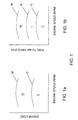
- FIG. 1a is a plot of engine load against engine speed.
- Engine speed may be measured, for example, by measuring the speed of crankshaft rotation in rotations per minute (RPM).
- Engine load measured on the vertical axis correlates to fuel to air ratio.
- FIG. 1a graphically illustrates two regions divided by line C determined by the "premixed combustion stability limit" of the fuel to air ratio for the engine.
- the premixed combustion stability limit is defined as the fuel to air ratio (F/A) at which the quantity of gaseous fuel within the piston cylinder will not support stable premixed combustion in any combustion mode.
- the premixed combustion mode may be by flame propagation or by homogeneous charge compression ignition (HCCI).
- HCCI is defined herein as a combustion mode, whereby combustion of the premixed fuel occurs at many points substantially simultaneously throughout the combustion chamber with substantially no flame propagation.
- HCCI is believed to be primarily controlled by chemical kinetics, with turbulence inside the combustion chamber having no significant influence on this mode of combustion. Therefore, the premixed combustion stability limit is distinguished from the flammability limit defined above, in that the flammability limit is defined as the F/A at which the quantity of gaseous fuel within the piston cylinder will not support a propagation mode of combustion.
- the load or F/A associated with the premixed combustion stability limit is lower than the load or F/A associated with the flammability limit. That is, by using the premixed combustion stability limit as the upper limit for low load operating region L, the extent of this region is reduced compared to the case where the flammability limit is employed as the upper limit for region L.
- An advantage of using the premixed combustion stability limit as the upper limit for low load operating region L is that the extent of high load operating region H (or intermediate load operating region I in Figure 1b) is increased.
- FIG. 1b there are three operating modes that correspond to predefined low, intermediate, and high load conditions. These three regions are graphically depicted in FIG. 1b.
- the horizontal axis again represents engine speed (that is, crankshaft rotation), measured in revolutions per minute (RPM), and the vertical axis, in this case, indicates fuel to air ratio, which is a parameter that correlates to the load on the engine.
- the fuel to air ratio increases with engine load for a fixed engine speed.
- Region L represents a low load region
- region I represents an area of intermediate load conditions
- region H represents an area corresponding to high load conditions .
- FIG. 1 The plots depicted in FIG. 1 (FIGs. 1a and 1b) show only the general shape of predefined regions that correspond to different operating modes.
- the actual numerical values for RPM and load or fuel to air ratio depend upon the individual characteristics of a particular engine design (for example, the size of the cylinder bore, the length of the stroke, the compression ratio, the shape of the combustion chamber, or the type of fuel). That is, engines of different design may have different regional boundaries between operating modes.
- the numerical values and the shape of the boundary line for a specific engine supplied with specific fuels may be determined empirically or theoretically.
- FIG. 2 illustrates a preferred method of introducing fuel into combustion chamber 10 when a low load operating mode is employed.
- Intake valve 11 and exhaust valve 12 are closed and piston 13 is at or near top dead center in piston cylinder 14.
- the power stroke is initiated by the introduction of pilot fuel 16 through injector 15.
- pilot fuel 16 is preferably introduced just before piston 13 reaches top dead center.
- pilot fuel 16 may be introduced between fifty degrees before top dead center and twenty degrees after top dead center (measured by degrees of crankshaft rotation).
- the actual timing within this range may be set with consideration to measured operating parameters such as engine speed. For example, as engine speed increases, pilot fuel 16 may be introduced into combustion chamber 10 earlier in the engine cycle so that combustion after the ignition delay will substantially coincide with when piston 13 is at or near top dead center.
- Main fuel 17 is preferably introduced into combustion chamber 10 sequentially, that is, after the introduction of pilot fuel 16.
- pilot fuel 16 and main fuel 17 may also be introduced simultaneously, for example, by commencing pilot and main fuel introduction simultaneously, or by overlapping fuel introduction (that is, introducing pilot fuel 16 first, but then introducing main fuel 17 while pilot fuel 16 is still being injected).
- Whether or not there is an overlap may depend, for example, upon engine speed and/or the quantity of fuel that is needed to satisfy the engine load. For example, as engine speed and the quantity of fuel increase, there may be more of an overlap.
- main fuel 17 when the low load operating mode is employed, main fuel 17 is not well mixed with the intake air and main fuel 17 bums in a diffusion mode.
- the low load operating mode less mixing is desirable to improve combustibility since the overall fuel to air ratio is below the premixed combustion stability limit.
- main fuel 17 is more concentrated and ignitable near the injector where pilot fuel is burning.
- pilot fuel 16 Like a conventional direct injection engine, compression of the intake air raises its temperature such that at the end of the compression stroke, the pressure and temperature within combustion chamber 10 is sufficient to ignite pilot fuel 16 after it is introduced (that is, after the ignition delay). The ignition of pilot fuel 16 ensures the ignition of main fuel 17.
- the quantities of pilot fuel 16 and main fuel 17 introduced in the low load operating mode may be adjusted depending upon the calculated total fuel requirement which is determined from the detected load conditions on the engine operating at a particular speed.
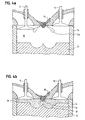
- FIG. 3 illustrates a preferred method of introducing fuel into combustion chamber 10 when a high load operating mode is employed.
- the high load operating mode introduces fuel to combustion chamber 10 in three stages.
- first stage depicted in FIG. 3a
- piston 13 is moving away from injector 15 during the intake stroke.
- Intake air is drawn into cylinder 14 through open intake valve 11.
- main fuel 17a is also introduced into cylinder 14 where it mixes with the intake air.
- first stage main fuel introduction may be timed to occur when piston 13 is at bottom dead center or during the compression stroke, when piston 13 is moving towards injector 15 and intake valve 11 is closed.
- delaying first stage main fuel introduction reduces the opportunity for main fuel 17a to mix with the intake air. Accordingly, if the first stage is timed to occur during the compression stroke, it is preferable for it to occur during the early part of the compression stroke, when piston 13 is near bottom dead center.
- the quantity of fuel introduced during the first stage is limited to reduce the likelihood of knocking.
- the maximum fuel to air ratio sustainable without causing knocking is referred to as the engine's knock limit.
- the second stage pilot fuel introduction preferably occurs during the compression stroke when piston 13 is near top dead center, as shown in FIG. 3b. Similar parameters are considered, as with the introduction of pilot fuel in the low load operating mode. That is, parameters such as engine speed should be taken into account to set the timing of the pilot fuel injection to allow for the ignition delay. Preferably, ignition is coordinated with about the time when piston 13 is at or near top dead center.
- first stage main fuel 17a injected earlier in the engine cycle has mixed with intake air to form substantially homogenous fuel-air mixture 18.
- pilot fuel 16 auto-ignites in combustion chamber 10, combustion of pilot fuel 16 ensures combustion of fuel-air mixture 18.
- the combustion of fuel and air mixture 18 yields benefits of at least a portion of the combustion being "lean burn homogeneous combustion" (that is, resulting in reduced emissions of NO x and particulate matter).
- pilot fuel 16 and third stage main fuel 17b may also be injected simultaneously or in an overlapping manner.
- the third stage occurs sequentially after and spaced by at least five degrees of crankshaft rotation from the second stage pilot fuel introduction.
- piston 13 is moving away from injector 15, propelled by the combustion of fuel in combustion chamber 10.
- the third stage preferably occurs no later than the early part of the power stroke, since introduction of additional fuel early in the power stroke has a greater effect than if it is added later.
- the third stage main fuel introduction is preferably completed before the crankshaft connected to piston 13 has rotated more than ninety degrees beyond the point when pilot fuel 16 was introduced.
- main fuel 17b is introduced at the end of the compression stroke or during the power stroke, it does not have an opportunity to thoroughly mix with the air in combustion chamber 10. Accordingly, third stage main fuel 17b burns in substantially a diffusion mode of combustion. Since the quantity of fuel introduced in the first stage is limited by the engine's knock limit, during high load conditions, engine power output is controlled by adjusting the quantity of main fuel 17b introduced during the third stage.
- the quantity of pilot fuel 16 represents about 1-15 % of the total quantity of fuel on an energy basis, with main fuel 17a and 17b providing the balance.
- the disclosed method of introducing main fuel and pilot fuel in three stages during high load conditions reduces the likelihood of knocking, provides efficient operation by utilizing both a lean premixed mode of combustion and a diffusion mode of combustion.
- An advantage of using the premixed combustion stability limit as the lower limit for high load operation (see FIG. 1a) or the lower limit for intermediate load operation (see FIG. 1b) is that this allows the engine to benefit from more lean burn homogeneous combustion (and reduced emissions) compared to the case when the flammability limit is used as this lower limit.
- This method also maintains high engine power output while reducing NO x and particulate matter emissions compared to conventional methods of operation.
- an intermediate operating mode may be selected when load conditions are within region I in FIG. 1b.
- the line between region I and region L is defined by the premixed combustion stability limit (C) and the line between region I and region H is defined by the knock limit (K).
- FIG. 4 illustrates a method of introducing fuel into combustion chamber 10 when an intermediate load operating mode is employed.
- the intermediate load operating mode introduces fuel to combustion chamber 10 in two stages.
- the fuel to air ratio is higher than the premixed combustion stability limit and lower than the knock limit, so all of main fuel 17a may be introduced into combustion chamber 10 during the first stage, depicted in FIG. 4a.
- the quantity of main fuel 17a introduced into combustion chamber 10 may be adjusted in response to engine load.
- piston 13 is moving away from injector 15 during the intake stroke. Intake air is drawn into cylinder 14 through open intake valve 11. Early introduction of main fuel 17a into cylinder 14 allows all of main fuel 17a to mix with the intake air during the remainder of the intake stroke and the whole of the compression stroke.
- main fuel introduction may be timed to occur during the compression stroke (not shown), when piston 13 is moving towards injector 15 and intake valve 11 is closed. However, as described above, delaying first stage main fuel introduction reduces the opportunity for main fuel 17a to mix with the intake air. Accordingly, if the first stage is timed to occur during the compression stroke, it is preferable for it to occur during the early part of the compression stroke, when piston 13 is near bottom dead center.
- the second stage occurs during the compression stroke, timed so that pilot fuel 16 ignites after the ignition delay, substantially when piston 13 is at or near top dead center at the beginning of the power stroke.
- first stage main fuel 17a has mixed with intake air to form substantially homogenous fuel-air mixture 18.
- pilot fuel 16 auto-ignites in combustion chamber 10
- the combustion of pilot fuel 16 and fuel-air mixture 18 begins. Because, in the intermediate load operating mode, all of the main fuel is well mixed with air in mixture 18, it provides the full benefits of "lean burn homogeneous combustion" (that is, reduced emissions of NO x and particulate matter).
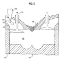
- FIG. 5 depicts an alternative arrangement for introducing main fuel 117 into cylinder 114 during the intake stroke when the intermediate or high load operating modes are employed.
- auxiliary injector 125 introduces main fuel 117 into the air induction system so that main fuel 117 mixes with air 120 before being drawn into combustion chamber 110.
- FIG. 5 depicts, for example, main fuel 117 being introduced into air induction passage 119 (that is, an air intake manifold).
- air induction passage 119 that is, an air intake manifold
- auxiliary injector 125 may also be located further upstream in the air induction system. Such premixing is known as "fumigation".
- the fuel-air mixture is then introduced to combustion chamber 110 during the intake stroke.
- the introduction of the mixture may be controlled by any known means, such as, for example, intake valve 111. Compression of the mixture, the pilot fuel injection phase, combustion, and subsequent introduction of additional main fuel (if any), proceed through injector 115, as depicted and explained above with reference to FIGs. 3b or 4b, depending upon whether it is a high load or an intermediate load condition.
- auxiliary injector 125 may be employed, or auxiliary injector 125 may be located further upstream in the air induction system to serve all of the pistons.
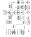
- the proportion of main fuel to pilot fuel and the timing for introducing fuel into the engine's combustion chamber is determined by an electronic control unit (ECU).
- ECU electronice control unit
- FIG. 6 is a control logic diagram that depicts the logic that such an ECU may be programmed to follow.
- a measurement subsystem 201 may be used to collect data relating to current operating conditions.
- measurement subsystem 201 collects data relating to the throttle position and the engine speed.
- Measurement subsystem 201 may optionally provide additional data, such as intake manifold charge temperature, engine coolant temperature, intake manifold charge pressure, air flow, and information that indicates the occurrence of knocking.
- the ECU preferably receives data indicating the measured throttle position and uses this data to calculate, on an energy basis, the total amount of fuel (Ft) required to satisfy the current engine load.
- the ECU determines the desired quantity of pilot fuel (Fp), which may be obtained, for example, from a look-up table that has been calibrated for the engine.
- the ECU may also receive data from measurement subsystem 201 that indicates the current air flow (A), or data that the ECU can use to calculate A.
- A current air flow
- ECU can calculate the main fuel to air ratio (that is, Fg/A).
- measurement subsystem 201 also sends data to the ECU indicating the current engine speed. Accordingly, with Fg/A and engine speed known, the ECU can determine the desired operating mode, by referring, for example, to a look-up table that stores information similar to that depicted in FIG. 1. In the preferred embodiment, a low load operating mode is selected if Fg/A is less than the premixed combustion stability limit (C), a high load operating mode is selected if Fg/A is greater than the knock limit (K), and an intermediate operating mode is selected if Fg/A is greater than C and less than K. The ECU may also determine whether a special operating condition, such as, for example, engine start up or idling exists. A special operating mode may be selected for the corresponding special operating condition.
- a special operating condition such as, for example, engine start up or idling exists.
- a special operating mode may be selected for the corresponding special operating condition.
- timing is set for introducing the fuel into the combustion chamber.
- timing and the sequence of main fuel and pilot fuel injection depends upon the selected operating mode.
- the specific timing within an operating mode may also be dictated by engine speed and the quantity of fuel to be injected. Accordingly, after the ECU determines the desired operating mode, main fuel and pilot fuel injection timing is set. Finally, the main fuel and pilot fuel are injected into the combustion chamber at the appropriately set times.
- the ECU may recalibrate its stored values in its memory to re-calibrate the value for knock limit K to prevent the re-occurrence of knocking. That is, if knocking is detected during a high load operating mode, the ECU may re-calibrate itself to reduce the quantity of main fuel (F fg ) that is introduced during the first stage. If knocking is detected during an intermediate load operating mode, the ECU may prevent the re-occurrence of knocking by re-calibrating itself to select the high load operating mode the next time the same load conditions are encountered.
- F fg main fuel
- the ECU may also recalibrate the premixed combustion stability limit and knock limit to compensate for changes in intake manifold pressure and temperature.
- the intake manifold temperature and pressure may be monitored and adjusted to maintain substantially constant values for predetermined operating conditions.
- throttle or "throttle position” has been used in a general sense to convey the load request on the engine.
- a load request is set by the user and may be a foot pedal placement (in the case of a vehicular engine) or a predetermined load request (in the case of a stationary energy generating engine).
- a user may set the load request and the term "throttle” (as used in this application) should be understood in this general sense.
Landscapes
- Engineering & Computer Science (AREA)
- Chemical & Material Sciences (AREA)
- Combustion & Propulsion (AREA)
- Mechanical Engineering (AREA)
- General Engineering & Computer Science (AREA)
- Oil, Petroleum & Natural Gas (AREA)
- Electrical Control Of Air Or Fuel Supplied To Internal-Combustion Engine (AREA)
- Output Control And Ontrol Of Special Type Engine (AREA)
- Combustion Methods Of Internal-Combustion Engines (AREA)
- Fuel-Injection Apparatus (AREA)
- Combined Controls Of Internal Combustion Engines (AREA)
Abstract
Claims (53)
- Procédé d'introduction d'un carburant dans une chambre de combustion d'un moteur à combustion interne en marche, ayant au moins un cylindre avec un piston, dans lequel ledit carburant comprend un carburant principal et un carburant pilote qui peut s'enflammer automatiquement plus que ledit carburant principal, ledit procédé étant caractérisé par :(a) la détection d'un ensemble de conditions de charge sur ledit moteur ;(b) l'emploi d'un mode de fonctionnement sous faible charge, lorsqu'un premier ensemble de conditions de charge est détecté, ledit premier ensemble prédéterminé de conditions de charge correspondant aux conditions de charge qui existent lorsque le rapport souhaité entre ledit carburant principal et l'air est inférieur à une limite de stabilité de combustion prémélangée d'un mélange homogène dudit carburant principal et de l'air d'admission, et l'emploi d'un mode de fonctionnement sous charge élevée, lorsqu'un deuxième ensemble prédéterminé de conditions de charge est détecté, dans lequel, pour un régime de moteur pouvant fonctionner comme mesuré sous la forme de tours par minute (tr/min) du vilebrequin, ledit deuxième ensemble de conditions de charge correspond à une charge de moteur qui est supérieure à la charge du moteur correspondant audit premier ensemble prédéterminé de conditions de charge ;(c) dans ledit mode de fonctionnement sous faible charge, l'introduction dudit carburant pilote et dudit carburant principal dans ladite chambre de combustion, lorsque ledit cylindre est mis sous pression, lorsque ledit piston est au niveau du point mort haut ou proche du point mort haut ;(d) dans ledit mode de fonctionnement sous charge élevée, l'introduction dudit carburant pilote et dudit carburant principal dans ladite chambre de combustion en trois étapes séquentielles, moyennant quoi une première partie dudit carburant principal est introduite, au cours d'une première étape, lors de la course d'admission et de compression, ledit carburant pilote est introduit, au cours d'une deuxième étape, lors de ladite course de compression, de telle sorte qu'il s'enflamme lorsque ledit piston est au niveau du point mort haut ou proche du point mort haut, et une deuxième partie dudit carburant principal est introduite au cours d'une troisième étape.
- Procédé selon la revendication 1, dans lequel ledit mode de fonctionnement sous faible charge comprend en outre l'introduction dudit carburant pilote, lors de la course de compression, de façon synchronisée, de telle sorte que ledit carburant pilote s'enflamme lorsque ledit piston est au niveau du point mort haut ou proche du point mort haut, et ledit carburant principal est introduit, de façon séquentielle, après ledit carburant pilote.
- Procédé selon la revendication 2, dans lequel, lorsqu'au moins une partie dudit carburant principal est introduite, de façon séquentielle, après ledit carburant pilote, ladite au moins une partie dudit carburant principal est introduite lorsque le vilebrequin a pivoté de zéro à quatre-vingt dix degrés après l'introduction dudit carburant pilote.
- Procédé selon la revendication 1, dans lequel l'introduction dudit carburant principal de la première étape, est terminée avant que ne débute l'introduction du carburant, au cours de la deuxième étape.
- Procédé selon la revendication 1, dans lequel ledit premier carburant principal de la première étape est introduit lors de ladite course d'admission.
- Procédé selon la revendication 1, dans lequel ledit premier carburant principal de la première étape est introduit lorsque ledit piston est au niveau du point mort bas ou proche du point mort bas.
- Procédé selon la revendication 1, dans lequel ledit carburant pilote de la deuxième étape est introduit, lorsque ledit piston est au niveau du point mort haut ou proche du point mort haut, vers la fin de ladite course de compression.
- Procédé selon la revendication 1, dans lequel ladite introduction du carburant pilote de la deuxième étape est terminée avant que ne débute l'introduction dudit carburant principal de la troisième étape.
- Procédé selon la revendication 1, dans lequel ledit carburant principal de la troisième étape est introduit lorsque le vilebrequin a pivoté d'au moins cinq degrés, après l'achèvement de l'introduction dudit carburant pilote de la deuxième étape.
- Procédé selon la revendication 1, comprenant en outre :(e) l'emploi d'un mode de fonctionnement sous charge intermédiaire, lorsqu'un troisième ensemble prédéterminé de conditions de charge est détecté, dans lequel, pour un régime du moteur pouvant fonctionner, ledit troisième ensemble prédéterminé de conditions de charge correspond à une charge du moteur qui est supérieure à la charge du moteur correspondant audit premier ensemble prédéterminé de conditions de charge et ledit troisième ensemble prédéterminé de conditions de charge correspond à une charge du moteur qui est inférieure à la charge du moteur correspondant audit deuxième ensemble prédéterminé de conditions de charge ;dans lequel ledit mode de fonctionnement sous charge intermédiaire comprend l'introduction, de façon séquentielle, dudit carburant pilote et dudit carburant principal dans ladite chambre de combustion, moyennant quoi ledit carburant principal est introduit dans ladite chambre de combustion avant que l'introduction dudit carburant pilote et dudit carburant principal n'ait lieu, lorsque ledit piston est au niveau du point mort haut ou proche du point mort haut, et l'introduction du carburant principal est synchronisée de telle sorte que ledit carburant pilote s'enflamme sensiblement, lorsque ledit piston est au niveau du point mort haut ou proche du point mort haut.
- Procédé selon la revendication 10, dans lequel on emploie ledit mode de fonctionnement sous charge intermédiaire, ledit carburant principal est introduit d'une manière telle qu'une quantité substantielle dudit carburant principal se mélange à l'air à l'intérieur dudit cylindre avant la combustion.
- Procédé selon la revendication 10, dans lequel ledit mode de fonctionnement sous charge intermédiaire est employé, ledit carburant principal est introduit dans ladite chambre de combustion lors d'une course d'admission.
- Procédé selon la revendication 10, dans lequel la limite entre ledit mode de fonctionnement sous charge intermédiaire et ledit mode de fonctionnement sous charge élevée est définie par une limite de résistance à la détonation étalonnée.
- Procédé selon la revendication 1, dans lequel la quantité dudit carburant principal introduit lors de ladite troisième étape est variable et dépend dudit ensemble détecté de conditions de charge, de telle sorte que la quantité dudit carburant principal introduit lors de ladite troisième étape augmente lorsque ledit ensemble détecté de conditions de charge indique que la charge du moteur est croissante.
- Procédé selon la revendication 14, dans lequel la quantité dudit carburant principal introduit au cours de ladite première étape est variable et dépend dudit ensemble détecté de conditions de charge et d'une limite de résistance à la détonation, de telle sorte que la quantité du carburant principal introduit au cours de ladite première étape maintient un rapport carburant principal/air, qui est inférieur à ladite limite de résistance à la détonation.
- Procédé selon la revendication 14, dans lequel la quantité dudit carburant principal introduit au cours de ladite première étape est sensiblement constante et fournit un rapport carburant principal/air qui est inférieur à une limite de résistance à la détonation étalonnée.
- Procédé selon la revendication 1, dans lequel la détection dudit ensemble de conditions de charge sur ledit moteur comprend la mesure du régime du moteur et de la position du papillon des gaz du moteur.
- Procédé selon la revendication 1, dans lequel la détection dudit ensemble de conditions de charge sur ledit moteur comprend la mesure de la température de charge de la tubulure d'admission du moteur et/ou de la température du liquide de refroidissement du moteur.
- Procédé selon la revendication 1, dans lequel la détection dudit ensemble de conditions de charge sur ledit moteur comprend la mesure de la pression de charge de la tubulure d'admission.
- Procédé selon la revendication 1, dans lequel la détection dudit ensemble de conditions de charge sur ledit moteur comprend la mesure de l'écoulement d'air dans ladite chambre de combustion.
- Procédé selon la revendication 1, dans lequel la détection dudit ensemble de conditions de charge sur ledit moteur comprend la détection de la résistance à la détonation à l'intérieur dudit cylindre.
- Procédé selon la revendication 1, dans lequel ledit carburant de la première étape est prémélangé avec l'air d'admission, avant d'être introduit dans ladite chambre de combustion.
- Procédé selon la revendication 10, dans lequel, dans ledit mode de fonctionnement sous charge intermédiaire, ledit carburant principal est mélangé à l'air d'admission avant d'être introduit dans ladite chambre de combustion.
- Procédé selon la revendication 1, comprenant en outre la définition d'un rapport prédéterminé entre le carburant principal et le carburant pilote (Fg/Fp), dépendant de l'ensemble détecté de conditions de charge sur ledit moteur, et l'introduction de quantités du carburant principal et du carburant pilot dans ladite chambre de combustion, selon ledit rapport prédéterminé Fg/Fp.
- Procédé selon la revendication 24, dans lequel la quantité de carburant principal introduit au cours de ladite première étape (Ffg), dans ledit mode de fonctionnement sous charge élevée, est limitée pour empêcher que le rapport du carburant à l'air (Ffg/A) ne dépasse une limite de résistance à la détonation étalonnée.
- Procédé selon la revendication 1, comprenant en outre l'emploi d'un système de contrôle pour contrôler la synchronisation pour l'introduction dudit carburant principal et dudit carburant pilote dans ladite chambre de combustion, selon ledit ensemble détecté de conditions de charge.
- Procédé selon la revendication 1, dans lequel ledit carburant principal est gazeux.
- Procédé selon la revendication 27, dans lequel ledit carburant principal est choisi dans le groupe constitué d'hydrogène gazeux et d'hydrocarbures gazeux.
- Procédé selon la revendication 28, dans lequel lesdits hydrocarbures gazeux comprennent du gaz naturel et du gaz de pétrole liquéfié.
- Procédé selon la revendication 1, dans lequel ledit carburant pilote est liquide.
- Procédé selon la revendication 30, dans lequel ledit carburant pilote est un hydrocarbure liquide.
- Procédé selon la revendication 31, dans lequel lesdits hydrocarbures liquides sont choisis dans le groupe constitué de carburant diesel et d'éther diméthylique.
- Procédé selon la revendication 1, dans lequel ledit moteur fournit de l'énergie à un véhicule ou ledit moteur est un composant générant l'énergie d'un groupe motopropulseur stationnaire.
- Procédé selon la revendication 1, comprenant en outre le fonctionnement, dans un mode de fonctionnement spécial, au cours des conditions spéciales prédéterminées, lorsqu'il n'est pas possible de réaliser efficacement la combustion d'un prémélange de carburant et d'une charge d'admission.
- Procédé selon la revendication 34, dans lequel lesdites conditions spéciales comprennent le démarrage du moteur et les conditions de ralenti du moteur.
- Procédé selon la revendication 34, dans lequel ledit mode de fonctionnement spécial est le même que ledit mode de fonctionnement sous faible charge.
- Procédé selon la revendication 1, comprenant en outre l'augmentation de la température de charge de la tubulure d'admission, au-dessus de la température ambiante, lorsqu'on emploie ledit mode de fonctionnement sous charge élevée.
- Procédé selon la revendication 37, comprenant en outre l'utilisation de la recirculation des gaz d'échappement pour augmenter la température de la charge d'admission.
- Procédé selon la revendication 10, comprenant en outre l'augmentation de la température de charge de la tubulure d'admission, au-dessus de la température ambiante, lorsqu'on emploie ledit mode de fonctionnement sous charge intermédiaire.
- Procédé selon la revendication 1, dans lequel ledit premier ensemble prédéterminé de conditions de charge correspond aux conditions de charge qui existent lorsque le rapport souhaité entre ledit carburant principal et l'air est inférieur à celui d'une limite d'inflammabilité étalonnée d'un mélange homogène dudit carburant principal et de l'air d'admission.
- Procédé de fonctionnement d'un moteur à combustion interne, dans lequel ledit procédé injecte dans une chambre de combustion un carburant principal et un carburant pilote qui peut s'enflammer automatiquement plus que ledit carburant principal, ledit procédé étant caractérisé par :(a) la détection d'un ensemble de conditions de fonctionnement du moteur et de la charge souhaitée du moteur ;(b) le calcul du carburant total requis en fonction de l'énergie pour satisfaire la charge souhaitée du moteur ;(c) la sélection d'une quantité prédéterminée de carburant pilote, en fonction dudit carburant total requis ;(d) le calcul de la quantité requise de carburant principal en fonction de l'énergie, selon une quantité égale audit carburant total requis moins ladite quantité prédéterminée de carburant pilote ;(e) la détermination de l'écoulement d'air à partir desdites conditions de fonctionnement du moteur ;(f) le calcul du rapport entre le carburant principal et l'air, en fonction de la quantité requise de carburant principal et ledit écoulement d'air déterminé ;(g) la détermination de l'existence d'une condition spéciale ;(h) la sélection d'un mode de fonctionnement spécial si ladite condition de fonctionnement spéciale existe, moyennant quoi, lorsque ledit mode de fonctionnement spécial est sélectionné, la distribution du carburant principal et du carburant pilote est établie de telle sorte que le carburant pilote est injecté pour initier la combustion et ledit carburant principal est injecté après l'injection dudit carburant pilote ;(i) si une condition de fonctionnement spéciale n'existe pas, ledit procédé comprend :la sélection d'un mode de fonctionnement sous faible charge, si ledit rapport entre le carburant principal et l'air est inférieur à une limite de stabilité de la combustion prémélangée prédéterminée (C), moyennant quoi, lorsque ledit mode de fonctionnement sous faible charge est sélectionné, la synchronisation de l'injection du carburant principal et du carburant pilote est établie, de telle sorte que le carburant pilote est injecté pour initier la combustion, et que ledit carburant principal est injecté après l'injection dudit carburant pilote ; etla sélection d'un mode de fonctionnement sous charge élevée, si ledit rapport entre le carburant principal et l'air est supérieur à C, moyennant quoi, lorsque ledit mode de fonctionnement sous charge élevée est sélectionné, ledit carburant principal est injecté en deux étapes, une première partie dudit carburant principal étant introduite avant l'injection dudit carburant pilote, ledit carburant pilote est injecté pour initier la combustion, et une deuxième partie du carburant principal est injecté après injection dudit carburant pilote.
- Procédé selon la revendication 41, comprenant en outre la sélection d'un mode de fonctionnement intermédiaire, lorsque ledit rapport entre le carburant principal et l'air est supérieur à C et inférieur à la limite de résistance à la détonation étalonnée, moyennant quoi, lorsque ledit mode de fonctionnement intermédiaire est sélectionné, ledit carburant principal est injecté avant l'injection dudit carburant pilote et ledit carburant pilote est injecté pour initier la combustion.
- Appareil d'introduction du carburant dans une chambre de combustion (10 ; 110) d'un moteur à combustion interne ayant au moins un cylindre (14 ; 114) avec un piston (13 ; 113) associé à celui-ci, ledit carburant comprenant un carburant principal (17 ; 117) et un carburant pilote (16 ; 116) qui peut s'enflammer automatiquement à un degré supérieur à celui dudit carburant principal, ledit appareil étant caractérisé par :(a) la mesure des dispositifs pour collecter des données opérationnelles à partir dudit moteur, où lesdits dispositifs de mesure comprennent un tachymètre, permettant de mesurer le régime du moteur, et un capteur, permettant de déterminer la position du papillon des gaz ;(b) une unité de contrôle électronique (201) qui reçoit lesdites données opérationnelles et les traite pour calculer un ensemble de conditions de charge, ladite unité de contrôle électronique comprend une mémoire permettant de stocker les ensembles de contrôle de conditions de charge et les modes de fonctionnement prédéterminés pour lesdits ensembles de contrôle des conditions de charge, ladite unité de contrôle électronique faisant correspondre ledit ensemble calculé de conditions de charge avec lesdits ensembles de contrôle de conditions de charge, pour sélectionner l'un desdits modes de fonctionnement prédéterminés ;(c) un injecteur de carburant principal (17 ; 117) contrôlé par ladite unité de contrôle électronique pour introduire ledit carburant principal dans ladite chambre de combustion, à des moments et en des quantités déterminés par ladite unité de contrôle électronique, selon lesdits modes de fonctionnement prédéterminés et ledit ensemble de conditions de charge ; et(d) un injecteur de carburant pilote (16 ; 116) contrôlé par ladite unité de contrôle électronique pour introduire ledit carburant pilote dans ladite chambre de combustion, à des moments et en des quantités déterminés par ladite unité de contrôle électronique, selon lesdits modes de fonctionnement prédéterminés et ledit ensemble de conditions de charge ;dans lequel lesdits modes de fonctionnement prédéterminés comprennent un mode de fonctionnement sous faible charge, lorsque ledit carburant pilote et ledit carburant principal sont introduits dans ladite chambre de combustion, lorsque ledit cylindre est mis sous pression ; et un mode de fonctionnement sous charge élevée qui comprend une introduction de carburant séquentielle en trois étapes dans ladite chambre de combustion, moyennant quoi une première partie dudit carburant principal est introduite au cours d'une première étape, ledit carburant pilote est introduit au cours d'une deuxième étape, et une deuxième partie dudit carburant principal est introduit au cours d'une troisième étape.
- Appareil selon la revendication 43, dans lequel lesdits dispositifs de mesure comprennent, en outre, une sonde pour mesurer la température de l'air d'admission du moteur.
- Appareil selon la revendication 43, dans lequel lesdits dispositifs de mesure comprennent, en outre, une sonde pour mesurer la température du liquide de refroidissement du moteur.
- Appareil selon la revendication 43, dans lequel lesdits dispositifs de mesure comprennent, en outre, un dispositif pour mesurer la pression de suralimentation de l'air d'admission.
- Appareil selon la revendication 43, dans lequel lesdits dispositifs de mesure comprennent, en outre, un débitmètre pour mesurer l'écoulement d'air dans ladite chambre de combustion.
- Appareil selon la revendication 43, dans lequel lesdits dispositifs de mesure comprennent, en outre, un dispositif pour détecter la détonation anticipée, à l'intérieur de ladite chambre de combustion.
- Appareil selon la revendication 48, dans lequel ladite unité de contrôle électronique peut réduire la quantité introduite dudit carburant principal, au cours de ladite première étape, lorsqu'on détecte la détonation anticipée.
- Appareil selon la revendication 43, dans lequel ledit injecteur de carburant principal et ledit injecteur de carburant pilote sont intégrés dans un injecteur de deux carburants, qui peut injecter séparément chacun dudit carburant principal et dudit carburant pilote.
- Appareil selon la revendication 43, comprenant, en outre, un injecteur auxiliaire associé à un système d'induction de l'air pour introduire le carburant principal dans un passage d'induction, de telle sorte qu'il peut se mélanger à l'air d'admission, avant d'être introduit dans ladite chambre de combustion.
- Appareil selon la revendication 51, dans lequel ledit passage d'induction de l'air est une tubulure d'induction de l'air.
- Appareil selon la revendication 51, dans lequel ledit moteur comprend une pluralité de pistons et une pluralité d'injecteurs auxiliaires.
Applications Claiming Priority (5)
| Application Number | Priority Date | Filing Date | Title |
|---|---|---|---|
| US09/503,034 US6202601B1 (en) | 2000-02-11 | 2000-02-11 | Method and apparatus for dual fuel injection into an internal combustion engine |
| US503034 | 2000-02-11 | ||
| US69050300A | 2000-10-17 | 2000-10-17 | |
| US690503 | 2000-10-17 | ||
| PCT/CA2001/000161 WO2001059280A1 (fr) | 2000-02-11 | 2001-02-09 | Procede et dispositif d'injection double de carburant dans un moteur a combustion interne |
Publications (2)
| Publication Number | Publication Date |
|---|---|
| EP1255923A1 EP1255923A1 (fr) | 2002-11-13 |
| EP1255923B1 true EP1255923B1 (fr) | 2006-04-12 |
Family
ID=27054365
Family Applications (1)
| Application Number | Title | Priority Date | Filing Date |
|---|---|---|---|
| EP01905536A Expired - Lifetime EP1255923B1 (fr) | 2000-02-11 | 2001-02-09 | Procede et dispositif d'injection double de carburant dans un moteur a combustion interne |
Country Status (7)
| Country | Link |
|---|---|
| EP (1) | EP1255923B1 (fr) |
| JP (1) | JP2003522877A (fr) |
| CN (1) | CN1236205C (fr) |
| AU (1) | AU2001233533A1 (fr) |
| CA (1) | CA2398149A1 (fr) |
| DE (1) | DE60118706T2 (fr) |
| WO (1) | WO2001059280A1 (fr) |
Cited By (4)
| Publication number | Priority date | Publication date | Assignee | Title |
|---|---|---|---|---|
| CN102472175A (zh) * | 2009-07-16 | 2012-05-23 | 戴姆勒股份公司 | 气态和液态燃料内燃机的运行方法以及内燃机 |
| CN109098865A (zh) * | 2018-09-29 | 2018-12-28 | 哈尔滨工程大学 | 一种基于反应活性控制的均匀预混天然气-柴油双燃料发动机燃烧控制方法 |
| WO2023272392A1 (fr) * | 2021-06-29 | 2023-01-05 | Westport Fuel Systems Canada Inc. | Appareil et procédé d'injection d'un carburant pilote dans un moteur à combustion interne |
| US12085050B2 (en) | 2022-10-26 | 2024-09-10 | Caterpillar Inc. | Switching fuel rail for a diesel fuel engine |
Families Citing this family (62)
| Publication number | Priority date | Publication date | Assignee | Title |
|---|---|---|---|---|
| US6675748B2 (en) * | 2000-02-11 | 2004-01-13 | Westport Research Inc. | Method and apparatus for fuel injection into an internal combustion engine |
| US6912992B2 (en) * | 2000-12-26 | 2005-07-05 | Cummins Westport Inc. | Method and apparatus for pilot fuel introduction and controlling combustion in gaseous-fuelled internal combustion engine |
| ES2387479T3 (es) * | 2001-08-29 | 2012-09-24 | Niigata Power Systems Co., Ltd. | Motor de gas de ignición por combustible líquido piloto, y método de funcionamiento de un motor de gas de ignición por combustible líquido piloto |
| CA2406137C (fr) * | 2002-10-02 | 2004-12-28 | Westport Research Inc. | Appareil et methode de regulation pour moteur a combustion interne alimente au carburant gazeux |
| US7021276B2 (en) * | 2004-03-25 | 2006-04-04 | International Engine Intellectual Property Company, Llc | Control strategy for HCCI-CD combustion in a diesel engine using two fuel injection phases |
| JP4281610B2 (ja) * | 2004-04-27 | 2009-06-17 | 株式会社豊田自動織機 | 予混合圧縮自着火機関の運転方法及び予混合圧縮自着火機関 |
| JP4003764B2 (ja) * | 2004-08-04 | 2007-11-07 | トヨタ自動車株式会社 | 水素添加内燃機関の制御装置 |
| JP2006052686A (ja) * | 2004-08-12 | 2006-02-23 | Toyota Motor Corp | 内燃機関の制御装置 |
| CN100434664C (zh) * | 2005-06-06 | 2008-11-19 | 株式会社丰田自动织机 | 均质充量压缩点火式内燃机 |
| DE102006020223B3 (de) * | 2006-05-02 | 2007-08-02 | Ford Global Technologies, LLC, Dearborn | Verfahren zur direkten Kraftstoffeinspritzung in einen Zylinder einer Brennkraftmaschine und Einspritzdüse zur Durchführung der Einspritzung |
| JP4535051B2 (ja) * | 2006-09-28 | 2010-09-01 | トヨタ自動車株式会社 | 多種燃料内燃機関 |
| DE112007002649A5 (de) * | 2006-10-11 | 2009-08-06 | Goldschmitt Techmobil Gmbh | Dieselmotor |
| CN100572777C (zh) * | 2006-12-28 | 2009-12-23 | 刘学文 | 汽车汽油与醇类混合使用方法及燃料供给系统和控制器 |
| DE102007039313A1 (de) * | 2007-08-20 | 2009-02-26 | Stadtbahn Saar Gmbh | Kraftstoffzuführungssystem für einen gleichzeitig mit unterschiedlichen Kraftstoffen betriebenen Verbrennungsmotor |
| DE102008007325A1 (de) * | 2008-02-02 | 2009-08-13 | Man Diesel Se | Prüfverfahren für Zündfluid-Injektoren |
| EP2449243B1 (fr) * | 2009-07-03 | 2019-03-06 | Volvo Truck Corporation | Procédé permettant de faire fonctionner un moteur à combustion à deux combustibles du type diesel et moteur à combustion à deux combustibles du type diesel fonctionnant selon un tel procédé |
| CN102116222B (zh) * | 2010-01-06 | 2012-12-05 | 张小平 | 电喷活塞式发动机油气双燃料电喷器 |
| FI20106325A0 (fi) * | 2010-12-15 | 2010-12-15 | Waertsilae Finland Oy | Menetelmä mäntämoottorin käyttämiseksi, ohjausjärjestelmä polttomoottorin toiminnan ohjaamiseksi ja mäntämoottori |
| DE102011003909B4 (de) | 2011-02-10 | 2018-05-30 | Man Diesel & Turbo Se | Zweitaktbrennkraftmaschine und Verfahren zum Betreiben derselben |
| JP5729467B2 (ja) * | 2011-05-13 | 2015-06-03 | トヨタ自動車株式会社 | 内燃機関の制御装置及び方法 |
| US8596561B2 (en) * | 2011-08-31 | 2013-12-03 | Caterpillar Inc. | Dual fuel injector with hydraulic lock seal |
| FR2980528B1 (fr) * | 2011-09-22 | 2013-08-30 | IFP Energies Nouvelles | Procede de controle de la combustion d'un moteur a combustion interne a injection directe d'essence, notamment a allumage commande |
| DE102011089292A1 (de) * | 2011-12-20 | 2013-06-20 | Robert Bosch Gmbh | Verfahren und Vorrichtung zur Klopfregelung einer Brennkraftmaschine |
| DE102012204382B4 (de) * | 2012-03-20 | 2025-11-20 | Everllence Se | Verfahren zum Betreiben einer Hubkolbenbrennkraftmaschine |
| CN102817732B (zh) * | 2012-09-11 | 2015-12-16 | 潍柴动力股份有限公司 | 一种双燃料发动机的柴油喷射控制方法及装置 |
| JP2014098339A (ja) * | 2012-11-14 | 2014-05-29 | Mitsubishi Heavy Ind Ltd | ディーゼルエンジンの制御装置、ディーゼルエンジン、及びディーゼルエンジンの制御方法 |
| JP6049415B2 (ja) * | 2012-11-14 | 2016-12-21 | 三菱重工業株式会社 | ディーゼルエンジンの制御装置、ディーゼルエンジン、及びディーゼルエンジンの制御方法 |
| DE102012222368A1 (de) * | 2012-12-06 | 2014-06-12 | Schaeffler Technologies Gmbh & Co. Kg | Motorsteuergerät für einen Zündstrahlmotor und Verfahren zum Betrieb eines Zündstrahlmotors |
| US9494090B2 (en) * | 2013-03-07 | 2016-11-15 | GM Global Technology Operations LLC | System and method for controlling an engine in a bi-fuel vehicle to prevent damage to a catalyst due to engine misfire |
| KR20140132826A (ko) * | 2013-05-07 | 2014-11-19 | 현대중공업 주식회사 | 이중연료엔진의 연소시작시기 제어를 통한 실린더 밸런싱 장치 및 방법 |
| EP2806140B1 (fr) * | 2013-05-24 | 2016-03-23 | Caterpillar Motoren GmbH & Co. KG | Moteur à double flux et son procédé de fonctionnement |
| CN103321761A (zh) * | 2013-06-28 | 2013-09-25 | 贵阳学院 | 一种乙醇-柴油双直喷发动机 |
| CA2826435C (fr) * | 2013-09-06 | 2016-01-05 | Westport Power Inc. | Systeme de combustion pour moteur a combustion interne a combustible gazeux |
| EP3049661B1 (fr) * | 2013-09-25 | 2017-08-23 | Wärtsilä Finland Oy | Procédé permettant de faire fonctionner un moteur à piston et moteur à piston |
| DK178962B1 (en) * | 2013-10-23 | 2017-07-03 | Man Diesel & Turbo Filial Af Man Diesel & Turbo Se Tyskland | A self-igniting internal combustion engine having a gaseous fuel supply system with pilot oil injection |
| KR101561073B1 (ko) | 2013-12-11 | 2015-10-16 | 에스티엑스조선해양 주식회사 | 점화연료 공급 장치 및 이를 갖는 가스엔진 시스템 |
| CA2838120C (fr) | 2013-12-23 | 2015-06-23 | Westport Power Inc. | Methode et appareil d'injection de carburant et commande de combustion dynamique |
| CN103883414B (zh) * | 2014-03-21 | 2017-09-01 | 北京工业大学 | 运用二甲醚和压缩天然气的电子喷射装置及控制方法 |
| US9689333B2 (en) * | 2014-07-28 | 2017-06-27 | Cummins Inc. | Dual-fuel engine with enhanced cold start capability |
| KR20160041523A (ko) * | 2014-10-08 | 2016-04-18 | 현대중공업 주식회사 | 이중연료엔진의 노킹 강도 제어를 이용한 실린더 밸런싱 장치 및 방법 |
| DE102014017124B4 (de) | 2014-11-20 | 2024-11-07 | Man Energy Solutions Se | Verfahren und Steuerungseinrichtung zum Betreiben eines Motors |
| AT516490B1 (de) | 2014-12-19 | 2016-06-15 | Ge Jenbacher Gmbh & Co Og | Verfahren zum Betreiben einer funkengezündeten Brennkraftmaschine |
| AT516543B1 (de) | 2014-12-19 | 2021-01-15 | Innio Jenbacher Gmbh & Co Og | Verfahren zum Betreiben einer funkengezündeten Brennkraftmaschine |
| DE102015002131B4 (de) * | 2015-02-19 | 2019-03-14 | Woodward L'orange Gmbh | Anordnung mit einer Injektorvorrichtung für das Ausdüsen von Brenngas und Flüssigkraftstoff |
| AT517205B1 (de) | 2015-06-23 | 2016-12-15 | Ge Jenbacher Gmbh & Co Og | Dual-Fuel-Brennkraftmaschine |
| CN105114194A (zh) * | 2015-08-17 | 2015-12-02 | 沈阳航空航天大学 | 通用飞机双燃料发动机燃烧系统及方法 |
| DE102015015343B4 (de) * | 2015-11-26 | 2024-11-14 | Man Energy Solutions Se | Verfahren und Steuerungseinrichtung zum Betreiben eines Motors |
| CN105649810A (zh) * | 2016-02-04 | 2016-06-08 | 大连理工大学 | 双燃料发动机燃料喷射方式 |
| JP6292249B2 (ja) * | 2016-03-31 | 2018-03-14 | マツダ株式会社 | 予混合圧縮着火式エンジン |
| DE102016116039A1 (de) * | 2016-08-29 | 2018-03-01 | Abb Turbo Systems Ag | Gasbetriebene brennkraftmaschine und verfahren zu deren betrieb |
| JP6755901B2 (ja) * | 2017-06-23 | 2020-09-16 | エムエーエヌ・エナジー・ソリューションズ・フィリアル・アフ・エムエーエヌ・エナジー・ソリューションズ・エスイー・ティスクランド | 大型ターボ過給式2ストローク圧縮着火型内燃エンジンおよび該エンジンの運転方法 |
| DE102017220108A1 (de) * | 2017-11-10 | 2019-05-16 | Mtu Friedrichshafen Gmbh | Verfahren zum Betreiben einer Brennkraftmaschine, Zweistoff-Injektoreinrichtung und Brennkraftmaschine, eingerichtet zur Durchführung eines solchen Verfahrens |
| US10823106B1 (en) * | 2019-05-13 | 2020-11-03 | Caterpillar Inc. | Early pilot lean burn strategy in dual fuel engine using targeted pilot flames |
| CN110318891B (zh) * | 2019-06-26 | 2022-01-14 | 哈尔滨工程大学 | 一种天然气/柴油双燃料发动机多模式燃烧组织方法 |
| DE102019209232A1 (de) * | 2019-06-26 | 2020-12-31 | Technische Universität München | HPDF-Betriebsverfahren für eine Brennkraftmaschine, Brennkraftmaschine und Arbeitsvorrichtung |
| CN112459911A (zh) * | 2020-11-26 | 2021-03-09 | 中船动力研究院有限公司 | 一种双燃料机的燃烧方法 |
| CN112555016A (zh) * | 2020-12-11 | 2021-03-26 | 哈尔滨工程大学 | 一种氨气耦合高活性燃料的燃烧室 |
| CN112814808B (zh) * | 2021-01-07 | 2021-12-28 | 中国第一汽车股份有限公司 | 一种气体燃料发动机的双喷射系统及其控制方法 |
| DE102021200463A1 (de) | 2021-01-19 | 2022-07-21 | Rolls-Royce Solutions GmbH | Verfahren zum Betreiben einer Brennkraftmaschine und Brennkraftmaschine |
| JP2024027920A (ja) * | 2022-08-19 | 2024-03-01 | ヤンマーホールディングス株式会社 | エンジン、制御装置、及び制御プログラム |
| CN116792226B (zh) * | 2023-07-14 | 2026-03-27 | 中国船舶集团有限公司第七一一研究所 | 用于内燃机的氢燃料供给方法、系统及其燃烧组件 |
| WO2025098592A1 (fr) * | 2023-11-07 | 2025-05-15 | Wärtsilä Finland Oy | Soupape d'injection directe, procédé de fabrication d'une soupape d'injection directe, moteur à piston à combustion interne, procédé de fonctionnement d'un moteur à piston à combustion interne et système de commande informatique pour faire fonctionner un moteur à piston à combustion interne |
Family Cites Families (4)
| Publication number | Priority date | Publication date | Assignee | Title |
|---|---|---|---|---|
| DE3442628A1 (de) * | 1984-11-22 | 1986-05-22 | Michael Dipl.-Ing. 8000 München Simon | Schadstoffarmer integral-verbrennungsmotor mit dualtreibstoffzufuhr |
| US5119780A (en) * | 1991-06-11 | 1992-06-09 | Southwest Research Institute | Staged direct injection diesel engine |
| US6032617A (en) * | 1998-05-27 | 2000-03-07 | Caterpillar Inc. | Dual fuel engine which ignites a homogeneous mixture of gaseous fuel, air, and pilot fuel |
| DE19826477C2 (de) * | 1998-06-13 | 2000-04-06 | Mak Motoren Gmbh & Co Kg | Brennkraftmaschine |
-
2001
- 2001-02-09 CA CA002398149A patent/CA2398149A1/fr not_active Abandoned
- 2001-02-09 EP EP01905536A patent/EP1255923B1/fr not_active Expired - Lifetime
- 2001-02-09 AU AU2001233533A patent/AU2001233533A1/en not_active Abandoned
- 2001-02-09 WO PCT/CA2001/000161 patent/WO2001059280A1/fr not_active Ceased
- 2001-02-09 JP JP2001558593A patent/JP2003522877A/ja active Pending
- 2001-02-09 CN CNB018048625A patent/CN1236205C/zh not_active Expired - Fee Related
- 2001-02-09 DE DE60118706T patent/DE60118706T2/de not_active Expired - Lifetime
Cited By (4)
| Publication number | Priority date | Publication date | Assignee | Title |
|---|---|---|---|---|
| CN102472175A (zh) * | 2009-07-16 | 2012-05-23 | 戴姆勒股份公司 | 气态和液态燃料内燃机的运行方法以及内燃机 |
| CN109098865A (zh) * | 2018-09-29 | 2018-12-28 | 哈尔滨工程大学 | 一种基于反应活性控制的均匀预混天然气-柴油双燃料发动机燃烧控制方法 |
| WO2023272392A1 (fr) * | 2021-06-29 | 2023-01-05 | Westport Fuel Systems Canada Inc. | Appareil et procédé d'injection d'un carburant pilote dans un moteur à combustion interne |
| US12085050B2 (en) | 2022-10-26 | 2024-09-10 | Caterpillar Inc. | Switching fuel rail for a diesel fuel engine |
Also Published As
| Publication number | Publication date |
|---|---|
| AU2001233533A1 (en) | 2001-08-20 |
| DE60118706D1 (de) | 2006-05-24 |
| DE60118706T2 (de) | 2006-11-16 |
| CN1236205C (zh) | 2006-01-11 |
| CN1401053A (zh) | 2003-03-05 |
| JP2003522877A (ja) | 2003-07-29 |
| CA2398149A1 (fr) | 2001-08-16 |
| WO2001059280A1 (fr) | 2001-08-16 |
| EP1255923A1 (fr) | 2002-11-13 |
Similar Documents
| Publication | Publication Date | Title |
|---|---|---|
| EP1255923B1 (fr) | Procede et dispositif d'injection double de carburant dans un moteur a combustion interne | |
| US6202601B1 (en) | Method and apparatus for dual fuel injection into an internal combustion engine | |
| US6912992B2 (en) | Method and apparatus for pilot fuel introduction and controlling combustion in gaseous-fuelled internal combustion engine | |
| US6675748B2 (en) | Method and apparatus for fuel injection into an internal combustion engine | |
| JP3920526B2 (ja) | 火花点火式成層燃焼内燃機関 | |
| US6684852B2 (en) | Internal combustion engine operable in PCCI mode with post-ignition injection and method of operation | |
| CN100416065C (zh) | 用于内燃机中气态燃料的引入及控制燃烧的方法和装置 | |
| US6640773B2 (en) | Method and apparatus for gaseous fuel introduction and controlling combustion in an internal combustion engine | |
| US7121254B2 (en) | Compression-ignited IC engine and method of operation | |
| EP2449243B1 (fr) | Procédé permettant de faire fonctionner un moteur à combustion à deux combustibles du type diesel et moteur à combustion à deux combustibles du type diesel fonctionnant selon un tel procédé | |
| WO2011002352A1 (fr) | Procédé permettant d'améliorer loxydation tardive dans un moteur à combustion interne à deux combustibles du type diesel et moteur à combustion interne à deux combustibles du type diesel fonctionnant selon un tel procédé | |
| Rameez et al. | Estimation of assorted injection schedules on hydrogen-diesel dual fuel and reactivity controlled compression ignition modes in a medium duty automotive engine | |
| US6789511B2 (en) | Internal combustion engine with compression ignition | |
| JP2006052686A (ja) | 内燃機関の制御装置 | |
| EP4585797A1 (fr) | Procédé de commande de moteur à combustion et système de moteur à combustion | |
| Kathpalia et al. | Optimizing Efficiency of Reactivity Controlled Compression Ignition (RCCI) Engine: A Review |
Legal Events
| Date | Code | Title | Description |
|---|---|---|---|
| PUAI | Public reference made under article 153(3) epc to a published international application that has entered the european phase |
Free format text: ORIGINAL CODE: 0009012 |
|
| 17P | Request for examination filed |
Effective date: 20020905 |
|
| AK | Designated contracting states |
Kind code of ref document: A1 Designated state(s): AT BE CH CY DE DK ES FI FR GB GR IE IT LI LU MC NL PT SE TR |
|
| AX | Request for extension of the european patent |
Free format text: AL;LT;LV;MK;RO;SI |
|
| RBV | Designated contracting states (corrected) |
Designated state(s): AT BE CH CY DE FR GB IT LI |
|
| 17Q | First examination report despatched |
Effective date: 20041220 |
|
| GRAP | Despatch of communication of intention to grant a patent |
Free format text: ORIGINAL CODE: EPIDOSNIGR1 |
|
| RBV | Designated contracting states (corrected) |
Designated state(s): DE FR GB IT |
|
| GRAS | Grant fee paid |
Free format text: ORIGINAL CODE: EPIDOSNIGR3 |
|
| GRAA | (expected) grant |
Free format text: ORIGINAL CODE: 0009210 |
|
| AK | Designated contracting states |
Kind code of ref document: B1 Designated state(s): DE FR GB IT |
|
| PG25 | Lapsed in a contracting state [announced via postgrant information from national office to epo] |
Ref country code: IT Free format text: LAPSE BECAUSE OF FAILURE TO SUBMIT A TRANSLATION OF THE DESCRIPTION OR TO PAY THE FEE WITHIN THE PRESCRIBED TIME-LIMIT;WARNING: LAPSES OF ITALIAN PATENTS WITH EFFECTIVE DATE BEFORE 2007 MAY HAVE OCCURRED AT ANY TIME BEFORE 2007. THE CORRECT EFFECTIVE DATE MAY BE DIFFERENT FROM THE ONE RECORDED. Effective date: 20060412 |
|
| REG | Reference to a national code |
Ref country code: GB Ref legal event code: FG4D |
|
| REF | Corresponds to: |
Ref document number: 60118706 Country of ref document: DE Date of ref document: 20060524 Kind code of ref document: P |
|
| ET | Fr: translation filed | ||
| REG | Reference to a national code |
Ref country code: GB Ref legal event code: 732E |
|
| PLBE | No opposition filed within time limit |
Free format text: ORIGINAL CODE: 0009261 |
|
| STAA | Information on the status of an ep patent application or granted ep patent |
Free format text: STATUS: NO OPPOSITION FILED WITHIN TIME LIMIT |
|
| 26N | No opposition filed |
Effective date: 20070115 |
|
| REG | Reference to a national code |
Ref country code: FR Ref legal event code: TP |
|
| REG | Reference to a national code |
Ref country code: FR Ref legal event code: PLFP Year of fee payment: 16 |
|
| REG | Reference to a national code |
Ref country code: FR Ref legal event code: PLFP Year of fee payment: 17 |
|
| REG | Reference to a national code |
Ref country code: FR Ref legal event code: PLFP Year of fee payment: 18 |
|
| REG | Reference to a national code |
Ref country code: DE Ref legal event code: R082 Ref document number: 60118706 Country of ref document: DE Representative=s name: BAUER WAGNER PRIESMEYER PATENT- UND RECHTSANWA, DE |
|
| PGFP | Annual fee paid to national office [announced via postgrant information from national office to epo] |
Ref country code: IT Payment date: 20190222 Year of fee payment: 19 Ref country code: GB Payment date: 20190227 Year of fee payment: 19 Ref country code: DE Payment date: 20190227 Year of fee payment: 19 |
|
| PGFP | Annual fee paid to national office [announced via postgrant information from national office to epo] |
Ref country code: FR Payment date: 20190225 Year of fee payment: 19 |
|
| REG | Reference to a national code |
Ref country code: DE Ref legal event code: R119 Ref document number: 60118706 Country of ref document: DE |
|
| GBPC | Gb: european patent ceased through non-payment of renewal fee |
Effective date: 20200209 |
|
| PG25 | Lapsed in a contracting state [announced via postgrant information from national office to epo] |
Ref country code: FR Free format text: LAPSE BECAUSE OF NON-PAYMENT OF DUE FEES Effective date: 20200229 Ref country code: DE Free format text: LAPSE BECAUSE OF NON-PAYMENT OF DUE FEES Effective date: 20200901 Ref country code: GB Free format text: LAPSE BECAUSE OF NON-PAYMENT OF DUE FEES Effective date: 20200209 |
|
| PG25 | Lapsed in a contracting state [announced via postgrant information from national office to epo] |
Ref country code: IT Free format text: LAPSE BECAUSE OF NON-PAYMENT OF DUE FEES Effective date: 20200209 |