EP1256537A2 - Wickel aus streifen- oder bandförmigen Medien mit einer Identifikationskennzeichnung sowie Verfahren zur Herstellung - Google Patents
Wickel aus streifen- oder bandförmigen Medien mit einer Identifikationskennzeichnung sowie Verfahren zur Herstellung Download PDFInfo
- Publication number
- EP1256537A2 EP1256537A2 EP02007903A EP02007903A EP1256537A2 EP 1256537 A2 EP1256537 A2 EP 1256537A2 EP 02007903 A EP02007903 A EP 02007903A EP 02007903 A EP02007903 A EP 02007903A EP 1256537 A2 EP1256537 A2 EP 1256537A2
- Authority
- EP
- European Patent Office
- Prior art keywords
- tape
- strip
- roll
- web
- length
- Prior art date
- Legal status (The legal status is an assumption and is not a legal conclusion. Google has not performed a legal analysis and makes no representation as to the accuracy of the status listed.)
- Withdrawn
Links
Images


Classifications
-
- B—PERFORMING OPERATIONS; TRANSPORTING
- B65—CONVEYING; PACKING; STORING; HANDLING THIN OR FILAMENTARY MATERIAL
- B65H—HANDLING THIN OR FILAMENTARY MATERIAL, e.g. SHEETS, WEBS, CABLES
- B65H18/00—Winding webs
- B65H18/28—Wound package of webs
-
- B—PERFORMING OPERATIONS; TRANSPORTING
- B65—CONVEYING; PACKING; STORING; HANDLING THIN OR FILAMENTARY MATERIAL
- B65H—HANDLING THIN OR FILAMENTARY MATERIAL, e.g. SHEETS, WEBS, CABLES
- B65H19/00—Changing the web roll
- B65H19/22—Changing the web roll in winding mechanisms or in connection with winding operations
- B65H19/29—Securing the trailing end of the wound web to the web roll
-
- B—PERFORMING OPERATIONS; TRANSPORTING
- B65—CONVEYING; PACKING; STORING; HANDLING THIN OR FILAMENTARY MATERIAL
- B65H—HANDLING THIN OR FILAMENTARY MATERIAL, e.g. SHEETS, WEBS, CABLES
- B65H2301/00—Handling processes for sheets or webs
- B65H2301/40—Type of handling process
- B65H2301/41—Winding, unwinding
- B65H2301/414—Winding
- B65H2301/4148—Winding slitting
-
- B—PERFORMING OPERATIONS; TRANSPORTING
- B65—CONVEYING; PACKING; STORING; HANDLING THIN OR FILAMENTARY MATERIAL
- B65H—HANDLING THIN OR FILAMENTARY MATERIAL, e.g. SHEETS, WEBS, CABLES
- B65H2301/00—Handling processes for sheets or webs
- B65H2301/40—Type of handling process
- B65H2301/46—Splicing
- B65H2301/463—Splicing splicing means, i.e. means by which a web end is bound to another web end
- B65H2301/4631—Adhesive tape
-
- B—PERFORMING OPERATIONS; TRANSPORTING
- B65—CONVEYING; PACKING; STORING; HANDLING THIN OR FILAMENTARY MATERIAL
- B65H—HANDLING THIN OR FILAMENTARY MATERIAL, e.g. SHEETS, WEBS, CABLES
- B65H2301/00—Handling processes for sheets or webs
- B65H2301/50—Auxiliary process performed during handling process
- B65H2301/51—Modifying a characteristic of handled material
- B65H2301/516—Securing handled material to another material
- B65H2301/5163—Applying label, tab to handled material
Definitions
- the invention relates to a roll of strip or tape-shaped media in particular, tape-shaped magnetic data recording media with a Identification marking and a process for their production.
- Rolls of strip or ribbon-shaped media, especially magnetic Data recording media generally consist of a winding core that of the recording medium cut into the width of use often in one length of several thousand meters is wound up.
- the free end of the record carrier is fixed to the outermost turn of the winding.
- a label on the outside of the wrap which contains a product identification or a production batch code.
- Magnetic recording media essentially consist of a plastic carrier film and one applied thereon using known coating methods magnetizable coating.
- the manufacture of this magnetic Record carriers are usually made in a much larger width than the width necessary for the application.
- the record carrier becomes after the coating wound into so-called semi-finished rolls, their length is a multiple of the later usage length.
- the semi-finished rolls are converted into the for the Application necessary bandwidths, for example 1 ⁇ 2 "(12.7 mm) for video cassettes or 3.81 mm for compact audio cassettes with so-called slitting machines cut.
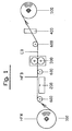
- FIG. 1 The basic structure of such a slitting machine is shown in FIG. 1 shown.
- the machine essentially consists of a unwind station (100) for wide semifinished rolls, a cutting and gluing table (200), a slitter (300), a band spread (400) for separating the Tapes cut to width, a winding station (500) for winding of the individual cut bands as well as several guide and Drive rollers (600) for transporting the wide, uncut semi-finished web (HFB) and the cut single strips (EB) in working width.
- a unwind station 100 for wide semifinished rolls
- a cutting and gluing table 200
- a slitter 300
- a band spread 400
- winding station 500
- EB uncut semi-finished web
- EB cut single strips
- the tape When at the take-up station (500) the tape winds up to a predetermined one Length are wound up, the cutting process is interrupted and the wide Semi-finished web (HFB) is on the cutting table (200) transverse to the longitudinal direction of the Ribbon cut through. Then the two are at the cutting table abutting tapes with one glued across the width of the web Adhesive tape connected again. Then the cutting process continued, the transversely attached adhesive tape cutting the slitter (300) runs through and also to the width of the cut Magnetic tape is cut, which is now in each tape there is a glue point that starts the end of the first tape (3) of the following band (4) connects, as can be seen from Fig. 2.
- the adhesive tape (5) with a print (7) be provided to label the tape roll with a product name or a Production batch code.
- this requires a sufficient dimension of the adhesive tape (5) ahead.
- the adhesive tape (5) with one for the selected printing processes such as dot matrix printers or thermal transfer printers suitable surface quality.
- the Andes Adhesive tape in this process made requirements in terms of width, non-sticky handle (6), printable surface require specially manufactured Adhesive tapes, which are relatively expensive.
- the cutting and gluing table (200) Connection between the first and subsequent tape so that a So-called "open” glue point (5.2) is formed, that is between the the first band (3) and the following band (4) is a sticky area (5.2) of the adhesive strip (5). If the "open" glue point (5.2) after the Longitudinal cutting arrives at the tape roll (1) The winding process is simply closed and the beginning of the next one Tape (4) is cut transversely behind the adhesive strip (5). The one on In this case, the remainder of the remaining ribbon (4) remains as Handle for opening the tape wrap, which shows Figure 4.
- Another object was to provide a process for making such To provide tape wraps; with no "open” glue point through the slitter to be transported.
- the first object was achieved according to the invention by one on a winding core wound tape-shaped data recording medium, the closure element the outermost winding layer on the tape winding is designed so that closed with a simple, narrow adhesive tape both the tape wrap as well as a label is attached so that this label as a handle for opening the sealing tape of the tape roll can be used.
- the second object was achieved with a method for producing the above described tape roll, the closure element of the tape roll including the label when passing through the junction between the end of a first semi-finished web and the start of one another semifinished web is formed by a slitting machine, the connection point consisting of an adhesive strip and a printed There is a label strip, the adhesive strip fixing the label strip in such a way that this can be used as a handle to open the finished tape roll.
- a tape wrap according to the invention is shown schematically in FIG. 6.
- the Closure element of the tape roll (10) wound on the winding core (20) consists of a narrow adhesive strip (50) with an adhesive underside (51), with the adhesive strip on one side the end of the last winding layer (3) of the winding (10) by a short distance, for example in the range of a few millimeters overlaps.
- the adhesive strip (50) overlaps by a few One millimeter with the identification mark (70) on its top printed label (60) with the adhesive strip on the top of the label (60) adheres.
- the adhesive tape is between the two overlapping areas mentioned (50) in an area (50.1) with the outer layer of the tape roll (10) bonded.
- the total length of the adhesive strip (50) results from the two Overlap areas to the outermost tape layer (3) or to the label (60) and the length of the bond (50.1) with the outer layer of the tape roll (10).
- the tape roll (10) fulfills the label (60) also the function of the handle for opening the tape roll at the Further processing of the tape, for example when cassetting.
- the Adhesive tape (50) can be used to differentiate between the types Band types in different colors.
- the advantage of the embodiment according to the invention is that the adhesive strip is narrow, no printable surface is required and no special one Form of assembly with an adhesive-free handle is necessary. Therefore a simple commercially available roll of tape is used as the adhesive strip expensive custom-made products are not required.
- the label can be made Paper or a plastic film.
- the invention Solution very inexpensive. Since the adhesive strip (50) is narrow, the Knives of the slitter only a short distance through the adhesive cut, which adversely affects the quality of the adhesive deposits on the Cutting knives can be reduced.
- a semi-finished roll is stored in the unwinding station (100) (HFR) unrolled and initially by means of guide rollers (600) guided contactlessly over the cutting table (200) and reaches the slitter (300).
- the resulting cut ribbons are cut into the band spread (400) fanned out and fed to the rewinder (500), where they are wound up into tapes. If the winding up the Tape winding have reached a predetermined length, the cutting process interrupted and the semi-finished web is released by releasing the belt tension lowered onto the cutting table (200).
- the cutting table has one porous surface, causing the semi-finished web to be sucked into the suction table and can thus be fixed. Then the semi-finished product line is along the line I-I cut across the direction (v) of the web.
- the two semi-finished products HFB1 and HFB2 directly next to each other fixed.
- the label strip (60) with a suitable printing device, for example Dot matrix printer or thermal transfer printer, transverse to its longitudinal direction with the Identification marking (70) printed, the printing in one Line spacing takes place, which corresponds to the width of the strips to be cut; for example 3.81 mm for compact audio tapes.
- the printed one The label strip is now on the semi-finished web pointing to the unwind station (100) HFB2 placed so that it is a distance A in the Has a size of a few millimeters. So that the label strip (60) in its position is fixed, the length L of the label strip is conveniently something chosen larger than the width W of the semi-finished web, so that the Label strips are sucked in at both ends on the cutting table (200) can.
- the adhesive tape (50) is attached so that it is both a Overlap. with the semi-finished train HFB1 in length B as well Has an overlap with the label strip (60) in length C. Thereby owns the adhesive strip (50) also connects to the semi-finished product HFB2 in the Length A.
- the application of the described invention is not for winding magnetic data carriers, but is also limited advantageously expandable with other strip or ribbon-shaped media.
Landscapes
- Replacement Of Web Rolls (AREA)
- Making Paper Articles (AREA)
- Manufacturing Of Magnetic Record Carriers (AREA)
- Magnetic Record Carriers (AREA)
- Adhesive Tapes (AREA)
- Storage Of Web-Like Or Filamentary Materials (AREA)
Abstract
Description
- Figur 1:
- eine schematische Darstellung einer Längsschneidemaschine
- Figur 2:
- eine schematische Darstellung einer Klebestelle nach dem Stand der Technik, kurz vor dem Erreichen des Bandwickels
- Figur 3:
- eine schematische Darstellung eines fertigen Bandwickels nach dem Stand der Technik
- Figur 4:
- eine schematische Darstellung eines Bandwickels nach dem Stand der Technik mit einer sogenannten offenen Klebestelle
- Figur 5:
- eine schematische Darstellung eines Bandwickels nach dem Stand der Technik mit einem separat befestigten Kennzeichnungsetikett
- Figur 6:
- eine schematische Darstellung eines erfindungsgemäßen Bandwickels mit Kennzeichnungsetikett
- Figur 7:
- eine schematische Seitenansicht eines Schneidtischs zum erfindungsgemäßen Herstellungsverfahren der Verbindungsstelle der Halbfabrikatbahnen
- Figur 8:
- eine entsprechende Draufsicht
Claims (6)
- Wickel aus streifen- oder bandförmigen Medien, insbesondere bandförmige magnetische Datenaufzeichnungsträger, bestehend aus einem Wickelkern (20) mit darauf aufgewickeltem streifen- oder bandförmigem Datenaufzeichnungsträger (10), dessen Bandende (3) mittels eines bedruckten Klebstreifens (5) auf dem Bandwickel (10) befestigt ist, dadurch gekennzeichnet, daß das Verschlußelement des Bandwickels (10) von einem Klebstreifen (50) mit klebender Unterseite (51) gebildet wird, wobei der Klebstreifen (50) mit seinem einen Ende das Ende (3) des aufgewickelten Bandes um eine Länge (B) überlappt und mit seinem anderen Ende einen Etikettstreifen (60) um eine Länge (C) überlappt, an dessen Oberseite er anhaftet, wobei der Klebstreifen (50) zwischen beiden Überlappungsbereichen in einem Bereich (50.1) mit der Länge (A) mit dem äußeren Umfang des Wickels (10) verklebt ist und wobei der Etikettstreifen (60) an seiner Oberseite mit einer Identifikationskennzeichnung (70) versehen ist.
- Wickel nach Anspruch 1, dadurch gekennzeichnet, daß der Etikettstreifen (60) aus Papier oder einer bedruckbaren Folie besteht.
- Wickel nach Anspruch 1 und 2, dadurch gekennzeichnet, daß der Etikettstreifen mittels eines Nadel- oder Thermotransferdruckers bedruckbar ist.
- Wickel (10) nach den Ansprüchen 1 bis 3, dadurch gekennzeichnet, daß der Klebstreifen (50) farbig ausgestaltet ist.
- Verfahren zur Herstellung eines Wickels aus streifen- oder bandförmigen Medien, insbesondere bandförmige magnetische Datenaufzeichnungsträger, bestehend aus einem Wickelkern (20) mit darauf aufgewickeltem streifen- oder bandförmigen Datenaufzeichnungsträger (10) und einem Verschlußelement (50,60,70) für den Wickel gemäß den Ansprüchen 1 bis 4, gekennzeichnet durch die Schritteeine von einer Abrollstation (100) kommende breite Halbfabrikatbahn (HFB) kommt in eine Längsschneideeinrichtung (300) und wird dort in einzelne Bänder (EB) in Gebrauchsbreite geschnitten und anschließend einer Aufwicklung (500) zugeführtbei Erreichen einer vorgegebenen Länge der Bandwickel wird die stehende Halbfabrikatbahn auf eine zwischen Abwicklung (100) und Längsschneideeinrichtung (300) angeordnete Querschneideeinrichtung (200) abgesenkt und quer geschnitten, wobei beide Bahnenden HFB1 und HFB2 lagefixiert werdenein Etikettstreifen (60), dessen Länge mindestens gleich der Bahnbreite der Halbfabrikatrolle ( HFR) ist und der so mit Identifikationskennzeichnungen bedruckt ist, daß der Zeilenabstand der Bedruckungen der Breite der Einzelbänder (EB) entspricht, wird so auf die nachfolgende Bahn (HFB2) gelegt, daß er gegenüber der Schnittlinie einen geringen Abstand (A) aufweistanschließend wird der Klebstreifen (50), dessen Länge in etwa der Bahnbreite der Halbfabrikatrollen ( HFR) entspricht, mit seiner klebenden Unterseite (51) auf die Bahnen in etwa mittig zur Schnittstelle so abgesenkt, daß er sowohl eine Überlappung der Länge (B) mit der ersten Halbfabrikatbahn (HFB1) als auch eine Überlappung der Länge (C) mit dem Etikettstreifen (60) besitzt und außerdem eine Verbindung der Länge (A) mit der zweiten Halbfabrikatbahn ( HFB2 ) hatdarauffolgend werden die so verbundenen Halbfabrikatbahnen (HFB1, HFB2) durch die Längsschneideeinrichtung (300) gefahren.bei Erreichen der Verbindungsstelle von HFB1 und HFB2 an der Aufwicklung (500) wird bei angehaltener Bahn durch Ziehen am Etikettstreifen (60) die Verbindungsstelle geöffnet und der dann freie klebrige Bereich (50.1) des längsgetrennten Klebstreifens (50) zwischen dem Bahnende (3) und dem Etikett (60) an der Außenlage des Bandwickels (10) angeklebt.
- Verfahren zur Herstellung eines Wickels gemäß Anspruch 5, dadurch gekennzeichnet, daß die Länge L des Etikettstreifens (60) etwas größer ist als die Breite der Halbfabrikatrolle (HFR).
Applications Claiming Priority (2)
| Application Number | Priority Date | Filing Date | Title |
|---|---|---|---|
| DE10122105A DE10122105A1 (de) | 2001-05-07 | 2001-05-07 | Wickel aus streifen- oder bandförmigen Medien mit einer Identifikationskennzeichnung sowie Verfahren zur Herstellung |
| DE10122105 | 2001-05-07 |
Publications (2)
| Publication Number | Publication Date |
|---|---|
| EP1256537A2 true EP1256537A2 (de) | 2002-11-13 |
| EP1256537A3 EP1256537A3 (de) | 2004-03-03 |
Family
ID=7683882
Family Applications (1)
| Application Number | Title | Priority Date | Filing Date |
|---|---|---|---|
| EP02007903A Withdrawn EP1256537A3 (de) | 2001-05-07 | 2002-04-09 | Wickel aus streifen- oder bandförmigen Medien mit einer Identifikationskennzeichnung sowie Verfahren zur Herstellung |
Country Status (7)
| Country | Link |
|---|---|
| US (1) | US20020164500A1 (de) |
| EP (1) | EP1256537A3 (de) |
| JP (1) | JP2003054793A (de) |
| KR (1) | KR20020085809A (de) |
| BR (1) | BR0201614A (de) |
| DE (1) | DE10122105A1 (de) |
| RU (1) | RU2002111646A (de) |
Cited By (1)
| Publication number | Priority date | Publication date | Assignee | Title |
|---|---|---|---|---|
| EP1840063A4 (de) * | 2005-01-17 | 2008-08-27 | Ishida Seisakusho | Filmrolle |
Families Citing this family (7)
| Publication number | Priority date | Publication date | Assignee | Title |
|---|---|---|---|---|
| US20090304998A1 (en) * | 2005-01-17 | 2009-12-10 | Ishida Co., Ltd. | Film roll |
| DE102008009102A1 (de) * | 2008-02-14 | 2009-08-20 | Rehau Ag + Co. | Kantenbandrolle |
| JP5772378B2 (ja) * | 2011-08-11 | 2015-09-02 | セイコーエプソン株式会社 | 印刷物製造方法 |
| JP6770855B2 (ja) * | 2016-08-31 | 2020-10-21 | 住友化学株式会社 | セパレータ捲回体、セパレータ捲回体の製造方法およびラベル検査方法 |
| US11267669B2 (en) * | 2017-03-22 | 2022-03-08 | Philip Morris Products S.A. | Method to remove an adhesive label from a bobbin and apparatus to detach an adhesive label from an end portion of a coiled sheet in a bobbin |
| CN110418593B (zh) * | 2017-10-20 | 2022-04-19 | 科亚列士信荣株式会社 | 半成品卷制造装置 |
| CN119218811B (zh) * | 2024-12-05 | 2025-03-11 | 浙江中特机械科技股份有限公司 | 一种高速标签自动分切机及其分切方法 |
Family Cites Families (4)
| Publication number | Priority date | Publication date | Assignee | Title |
|---|---|---|---|---|
| US4339294A (en) * | 1979-12-19 | 1982-07-13 | Ciba-Geigy Ag | Method and apparatus for making reeled strip material |
| US5366174A (en) * | 1991-10-08 | 1994-11-22 | Sony Magnescale, Inc. | Tape winding apparatus |
| JPH08180406A (ja) * | 1994-12-28 | 1996-07-12 | Sony Corp | 磁気テープの末端止め用粘着テープ及びそれを用いた磁気テープの製造方法 |
| DE19744103C2 (de) * | 1997-10-06 | 2002-12-05 | Emtec Magnetics Gmbh | Vorrichtung zum Schneiden, Ankleben und Kennzeichnen eines band- oder streifenförmigen Materials, insbesondere aus Papier |
-
2001
- 2001-05-07 DE DE10122105A patent/DE10122105A1/de not_active Withdrawn
-
2002
- 2002-04-09 EP EP02007903A patent/EP1256537A3/de not_active Withdrawn
- 2002-04-30 JP JP2002128338A patent/JP2003054793A/ja active Pending
- 2002-05-06 US US10/138,491 patent/US20020164500A1/en not_active Abandoned
- 2002-05-06 KR KR1020020024681A patent/KR20020085809A/ko not_active Withdrawn
- 2002-05-06 BR BR0201614-1A patent/BR0201614A/pt not_active Application Discontinuation
- 2002-05-06 RU RU2002111646/12A patent/RU2002111646A/ru not_active Application Discontinuation
Cited By (1)
| Publication number | Priority date | Publication date | Assignee | Title |
|---|---|---|---|---|
| EP1840063A4 (de) * | 2005-01-17 | 2008-08-27 | Ishida Seisakusho | Filmrolle |
Also Published As
| Publication number | Publication date |
|---|---|
| KR20020085809A (ko) | 2002-11-16 |
| BR0201614A (pt) | 2003-03-11 |
| US20020164500A1 (en) | 2002-11-07 |
| RU2002111646A (ru) | 2003-11-10 |
| JP2003054793A (ja) | 2003-02-26 |
| EP1256537A3 (de) | 2004-03-03 |
| DE10122105A1 (de) | 2002-11-14 |
Similar Documents
| Publication | Publication Date | Title |
|---|---|---|
| EP0450312B1 (de) | Verfahren zum Verbinden des Bahnanfanges eines Wickels an einer Splice-Stelle mit dem Bahnende einer von einem anderen Wickel ablaufenden Bahn | |
| DE4033900C2 (de) | Splice-Stelle am Bahnanfang eines Wickels zum Verbinden des Bahnanfangs mit dem Bahnende eines anderen Wickels | |
| DE4211216C2 (de) | Band mit doppelseitig klebenden Abschnitten und Verfahren zu dessen Herstellung | |
| DE4020954B4 (de) | Ansetzband, insbesondere zum fliegenden Ansetzen von Papierbahnen | |
| EP0500841B1 (de) | Verfahren und vorrichtung zum wechseln von wickelrollen | |
| DE2456342A1 (de) | Vorrichtung zum verbinden der stumpfen enden zweier aufeinanderfolgender baender | |
| EP0512196B1 (de) | Wickelmaschine zum Aufwickeln von Materialbahnen | |
| DE19841609A1 (de) | Haftelement oder -streifen für Fliegenden Rollenwechsel | |
| DE69612493T2 (de) | Wickeldorn und verfahren zum kernlosen wickeln von klebeband | |
| DE69816094T2 (de) | Vorrichtung zum rückfaltenfreien verbinden von bahnen mit elektrostatischer vorrichtung zur übergabe der bahn | |
| EP0031298B1 (de) | Verfahren und Vorrichtung zur Herstellung von Bandrollen | |
| DE69606448T2 (de) | Abwickelvorrichtung für bandförmiges Material | |
| DE10122105A1 (de) | Wickel aus streifen- oder bandförmigen Medien mit einer Identifikationskennzeichnung sowie Verfahren zur Herstellung | |
| US4475830A (en) | Spliceless ribbon structure having leader and trailer and method of manufacture therefor | |
| DE1262302B (de) | Verpackung eines auf einen Spulenkern aufgewickelten Farbbandes | |
| EP0683122B1 (de) | Klebemittel zum Verbinden von auf angetriebenen Rollen gewickelten Materialbahnen | |
| EP0963909B1 (de) | Verfahren und Vorrichtung zum Herstellen einer am Umfang verpackten Materialbahnrolle und Materialbahnrolle | |
| EP1167257B1 (de) | Verfahren zum Aufwickeln einer Materialbahn und Wickelvorrichtung | |
| WO1989008907A1 (fr) | Porte-etiquette a bandes et son dispositif de fabrication | |
| DE69306752T2 (de) | Vorrichtung zum Schneiden und Aufbringen eines Verbindungsstreifens für eine Bahnwickelvorrichtung | |
| DE102019110339A1 (de) | Druck- und Etikettiermaschine und Verfahren zum individualisierten Bedrucken von Etiketten | |
| EP0627377A1 (de) | Vorrichtung zum Verbinden von Materialbahnen | |
| DE10351877B4 (de) | Schneidvorrichtung zum Abtrennen von Etiketten, Verfahren zum Abtrennen von Etiketten und Druckvorrichtung | |
| DE19804411A1 (de) | Verfahren zum Überleiten einer Materialbahn von einer Wickelrolle auf eine Wickelhülse und Wickelvorrichtung | |
| DE19529177C2 (de) | Verfahren zum Herstellen von Selbstklebeetikettenbändern und nach diesem Verfahren hergestelltes Selbstklebeetikettenband |
Legal Events
| Date | Code | Title | Description |
|---|---|---|---|
| PUAI | Public reference made under article 153(3) epc to a published international application that has entered the european phase |
Free format text: ORIGINAL CODE: 0009012 |
|
| AK | Designated contracting states |
Kind code of ref document: A2 Designated state(s): AT BE CH CY DE DK ES FI FR GB GR IE IT LI LU MC NL PT SE TR |
|
| AX | Request for extension of the european patent |
Free format text: AL;LT;LV;MK;RO;SI |
|
| RAP1 | Party data changed (applicant data changed or rights of an application transferred) |
Owner name: EMTEC MAGNETICS GMBH |
|
| PUAL | Search report despatched |
Free format text: ORIGINAL CODE: 0009013 |
|
| AK | Designated contracting states |
Kind code of ref document: A3 Designated state(s): AT BE CH CY DE DK ES FI FR GB GR IE IT LI LU MC NL PT SE TR |
|
| AX | Request for extension of the european patent |
Extension state: AL LT LV MK RO SI |
|
| RIC1 | Information provided on ipc code assigned before grant |
Ipc: 7B 65H 19/29 A |
|
| AKX | Designation fees paid | ||
| REG | Reference to a national code |
Ref country code: DE Ref legal event code: 8566 |
|
| STAA | Information on the status of an ep patent application or granted ep patent |
Free format text: STATUS: THE APPLICATION IS DEEMED TO BE WITHDRAWN |
|
| 18D | Application deemed to be withdrawn |
Effective date: 20041102 |