EP1256543A2 - Mikrofluidisches Speicher- und/oder Dosierbauteil - Google Patents
Mikrofluidisches Speicher- und/oder Dosierbauteil Download PDFInfo
- Publication number
- EP1256543A2 EP1256543A2 EP02008129A EP02008129A EP1256543A2 EP 1256543 A2 EP1256543 A2 EP 1256543A2 EP 02008129 A EP02008129 A EP 02008129A EP 02008129 A EP02008129 A EP 02008129A EP 1256543 A2 EP1256543 A2 EP 1256543A2
- Authority
- EP
- European Patent Office
- Prior art keywords
- reservoir
- capillary
- outlet
- component
- displacement chamber
- Prior art date
- Legal status (The legal status is an assumption and is not a legal conclusion. Google has not performed a legal analysis and makes no representation as to the accuracy of the status listed.)
- Granted
Links
Images


Classifications
-
- B—PERFORMING OPERATIONS; TRANSPORTING
- B01—PHYSICAL OR CHEMICAL PROCESSES OR APPARATUS IN GENERAL
- B01L—CHEMICAL OR PHYSICAL LABORATORY APPARATUS FOR GENERAL USE
- B01L3/00—Containers or dishes for laboratory use, e.g. laboratory glassware; Droppers
- B01L3/02—Burettes; Pipettes
- B01L3/0241—Drop counters; Drop formers
- B01L3/0268—Drop counters; Drop formers using pulse dispensing or spraying, eg. inkjet type, piezo actuated ejection of droplets from capillaries
-
- B—PERFORMING OPERATIONS; TRANSPORTING
- B01—PHYSICAL OR CHEMICAL PROCESSES OR APPARATUS IN GENERAL
- B01L—CHEMICAL OR PHYSICAL LABORATORY APPARATUS FOR GENERAL USE
- B01L2200/00—Solutions for specific problems relating to chemical or physical laboratory apparatus
- B01L2200/04—Exchange or ejection of cartridges, containers or reservoirs
-
- B—PERFORMING OPERATIONS; TRANSPORTING
- B01—PHYSICAL OR CHEMICAL PROCESSES OR APPARATUS IN GENERAL
- B01L—CHEMICAL OR PHYSICAL LABORATORY APPARATUS FOR GENERAL USE
- B01L2200/00—Solutions for specific problems relating to chemical or physical laboratory apparatus
- B01L2200/06—Fluid handling related problems
- B01L2200/0615—Loss of fluid by dripping
-
- B—PERFORMING OPERATIONS; TRANSPORTING
- B01—PHYSICAL OR CHEMICAL PROCESSES OR APPARATUS IN GENERAL
- B01L—CHEMICAL OR PHYSICAL LABORATORY APPARATUS FOR GENERAL USE
- B01L2200/00—Solutions for specific problems relating to chemical or physical laboratory apparatus
- B01L2200/06—Fluid handling related problems
- B01L2200/0642—Filling fluids into wells by specific techniques
-
- B—PERFORMING OPERATIONS; TRANSPORTING
- B01—PHYSICAL OR CHEMICAL PROCESSES OR APPARATUS IN GENERAL
- B01L—CHEMICAL OR PHYSICAL LABORATORY APPARATUS FOR GENERAL USE
- B01L2200/00—Solutions for specific problems relating to chemical or physical laboratory apparatus
- B01L2200/06—Fluid handling related problems
- B01L2200/0684—Venting, avoiding backpressure, avoid gas bubbles
-
- B—PERFORMING OPERATIONS; TRANSPORTING
- B01—PHYSICAL OR CHEMICAL PROCESSES OR APPARATUS IN GENERAL
- B01L—CHEMICAL OR PHYSICAL LABORATORY APPARATUS FOR GENERAL USE
- B01L2200/00—Solutions for specific problems relating to chemical or physical laboratory apparatus
- B01L2200/16—Reagents, handling or storing thereof
-
- B—PERFORMING OPERATIONS; TRANSPORTING
- B01—PHYSICAL OR CHEMICAL PROCESSES OR APPARATUS IN GENERAL
- B01L—CHEMICAL OR PHYSICAL LABORATORY APPARATUS FOR GENERAL USE
- B01L2300/00—Additional constructional details
- B01L2300/08—Geometry, shape and general structure
- B01L2300/0809—Geometry, shape and general structure rectangular shaped
- B01L2300/0816—Cards, e.g. flat sample carriers usually with flow in two horizontal directions
-
- B—PERFORMING OPERATIONS; TRANSPORTING
- B01—PHYSICAL OR CHEMICAL PROCESSES OR APPARATUS IN GENERAL
- B01L—CHEMICAL OR PHYSICAL LABORATORY APPARATUS FOR GENERAL USE
- B01L2400/00—Moving or stopping fluids
- B01L2400/04—Moving fluids with specific forces or mechanical means
- B01L2400/0403—Moving fluids with specific forces or mechanical means specific forces
- B01L2400/0406—Moving fluids with specific forces or mechanical means specific forces capillary forces
-
- B—PERFORMING OPERATIONS; TRANSPORTING
- B01—PHYSICAL OR CHEMICAL PROCESSES OR APPARATUS IN GENERAL
- B01L—CHEMICAL OR PHYSICAL LABORATORY APPARATUS FOR GENERAL USE
- B01L2400/00—Moving or stopping fluids
- B01L2400/04—Moving fluids with specific forces or mechanical means
- B01L2400/0475—Moving fluids with specific forces or mechanical means specific mechanical means and fluid pressure
- B01L2400/0487—Moving fluids with specific forces or mechanical means specific mechanical means and fluid pressure fluid pressure, pneumatics
-
- B—PERFORMING OPERATIONS; TRANSPORTING
- B01—PHYSICAL OR CHEMICAL PROCESSES OR APPARATUS IN GENERAL
- B01L—CHEMICAL OR PHYSICAL LABORATORY APPARATUS FOR GENERAL USE
- B01L3/00—Containers or dishes for laboratory use, e.g. laboratory glassware; Droppers
- B01L3/50—Containers for the purpose of retaining a material to be analysed, e.g. test tubes
- B01L3/502—Containers for the purpose of retaining a material to be analysed, e.g. test tubes with fluid transport, e.g. in multi-compartment structures
- B01L3/5027—Containers for the purpose of retaining a material to be analysed, e.g. test tubes with fluid transport, e.g. in multi-compartment structures by integrated microfluidic structures, i.e. dimensions of channels and chambers are such that surface tension forces are important, e.g. lab-on-a-chip
- B01L3/502723—Containers for the purpose of retaining a material to be analysed, e.g. test tubes with fluid transport, e.g. in multi-compartment structures by integrated microfluidic structures, i.e. dimensions of channels and chambers are such that surface tension forces are important, e.g. lab-on-a-chip characterised by venting arrangements
-
- G—PHYSICS
- G01—MEASURING; TESTING
- G01N—INVESTIGATING OR ANALYSING MATERIALS BY DETERMINING THEIR CHEMICAL OR PHYSICAL PROPERTIES
- G01N35/00—Automatic analysis not limited to methods or materials provided for in any single one of groups G01N1/00 - G01N33/00; Handling materials therefor
- G01N35/10—Devices for transferring samples or any liquids to, in, or from, the analysis apparatus, e.g. suction devices, injection devices
- G01N2035/1027—General features of the devices
- G01N2035/1034—Transferring microquantities of liquid
- G01N2035/1039—Micropipettes, e.g. microcapillary tubes
Definitions
- the invention relates to a microfluidic storage and / or metering component.
- Microfluidic storage and / or metering components are used for the purposes of this application storing and / or dosing liquids.
- Characteristic of this Microfluidic components are microstructures, for example capillary channels or Openings with characteristic dimensions, e.g. the hydraulic Diameter of the channels belongs in the range from 5 ⁇ m to 1500 ⁇ m (preferably 10 ⁇ m to 500 ⁇ m) in one dimension.
- Microfluidic metering components can in particular Have dosing volumes in the nanoliter and microliter range. she can in particular from semiconductors and / or plastics and / or glass and / or Ceramics and / or metals can be produced, with suitable manufacturing processes Microtechnology or microstructuring can be used, e.g. lithograph and etching processes (for semiconductors) or league processes (for metals, plastics and ceramics).
- WO 99/10099 describes various microdosing systems which are suitable for Dosing volumes in the range from a few nanoliters to a few microliters are intended and with a free jet dosing device and / or a micro diaphragm pump work.
- One of these microdosing systems has a microsystem technology Dosing and reagent unit. This has a reservoir with a filter for pressure equalization with the environment and a micromembrane pump connected to it via a line and / or free jet dispenser. It also has an outside one Dispensing tube with a metering opening. There is also a dosing control for the Micro diaphragm pump available.
- the dosing and reagent unit is in one holder can be used in the foot area of a housing so that the dispensing tube is axial protrudes beyond the foot area.
- the dosing control is fixed in the base of the housing arranged optical sensor connected to the delivery tube of the insertable Dosing and reagent unit is assigned.
- This dispensing system is achieved by inserting one with a reagent (e.g. one Enzyme) pre-filled dosing and reagent unit in the housing for prepared the operation.
- a reagent e.g. one Enzyme
- the micromembrane pump pumps in the first metering step Liquid from the reservoir until the sensor detects the meniscus and thus one defined zero position reached. Then the dosing amount is above the known Controlled stroke volume of the micro diaphragm pump. If the dosing and reagent unit is emptied, it is replaced by a new, pre-filled unit.
- this document discloses a microdosing system with a capillary compensation system having reservoir, a free jet meter, the entrance with is connected to the capillary equalization system, one to the outlet of the free jet meter connected metering opening and one with the free jet meter in operative connection dosing control.
- the capillary compensation system is used for Storage and capillary transport of the liquid from the reservoir into the Free jet. It can also compensate for fluctuations in the Ambient conditions such as air pressure and temperature and that of the free jet dispenser volume of liquid used.
- the capillary compensation system prevents that when accelerating, for example when the reservoir falls, in the stored Liquid volume Bubbles occur that can interfere with the dosing process.
- the capillary compensation system can be connected to at least one of the the point away from the free jet dispenser must be ventilated so that liquid can escape is compensated for by inflowing air. Prevent the capillary forces then at the same time that the reservoir runs out. Also the microdosing system described above can have such a capillary compensation system.
- the object of the invention is a microfluidic To create storage and / or dosing component, in which the controlled storage and fluid delivery is further improved.
- the component can use a have any orientation, especially when dispensing in free jet.
- capillary cavities refers to the different solutions, "capillary riser", “capillary filler”, “capillary” or “Capillary connections” - hereinafter referred to as “capillary structures” - on cavities (e.g. channels or pores), channels (e.g. in the form of gaps, slits or tubes) or connections (e.g. channels or pores) in which wetting liquids rise or flow in one direction or are held by capillary forces and in which there is an increased capillary pressure when filled with wetting liquids at the interface with air or another gas.
- the extent of this Capillary effects can be influenced primarily by the dimensions of the capillary structures but also by their materials or surface properties. The The tendency of the capillary structures to these capillary effects is simplified below referred to as "capillarity”.
- the capillary cavities in the reservoir already reduce the Pressure of the liquid in the dosing outlet.
- the pressure of the liquid reduced in the metering output in that the reservoir and the displacement chamber are at least partially arranged at the same level as this is the hydrostatic Pressure of the liquid reduced.
- the capillaries are preferred Cavities and the levels of the reservoir and displacement chamber designed so that the capillary pressure of the liquid in the reservoir is at least the hydrostatic pressure corresponds to the liquid in the dosing outlet.
- the total pressure of the liquid in the Dosing output then corresponds at most to the ambient pressure, so that liquid does not leak automatically.
- the reservoir and / or the displacement chamber preferably each extend over a certain height. Included in the invention is that the reservoir and / or the displacement chamber only in parts of its entire height at the same Level are arranged. The reservoir and the displacement chamber are preferred arranged at substantially the same level along their entire height.
- the liquid rises from the reservoir into the Rise channel based on the principle of communicating tubes. Regardless of the level of the reservoir is the fluid supply even when the component is aligned vertically from the reservoir into the displacement chamber due to the rise of the liquid ensured in the capillary riser due to the capillary effect.
- the transition of liquid from the reservoir through the riser into the displacement chamber works in any orientation of the component, so that this in any orientation can be operated.
- the capillary cavities and secure capillary riser the complete, bubble-free filling of reservoir, riser and displacement chamber with liquid and act due to the formation of bubbles against impacts against the component.
- a connecting channel is arranged, which is assigned a level sensor is.
- the level sensor With the level sensor, the complete filling of the displacement chamber can be monitored with liquid to avoid incorrect dosing.
- the fill level sensor can in particular be an optical sensor, the bubbles and / or liquid or the phase boundary between them is detected.
- the capillary riser is laterally via a capillary gap connected to the reservoir, the capillary gap designed so is that in the dosing operation liquid essentially from the outlet of the reservoir flows through the capillary riser into the displacement chamber and that when arranged of the component in a direction opposite to the flow direction in the riser during metering operation directed centrifugal field liquid from the displacement chamber and the Rising channel flows through the gap into the reservoir.
- the gap preferably opens at least partially in a region of the reservoir above the capillary cavities. Liquid can be spilled in this area during centrifugation from the capillary riser directly into the upper area of the reservoir emerge to collect there, as well as the liquid from the capillaries Cavities of the reservoir. Although in the upper part of the reservoir due to the Ventilation opening there is ambient pressure, the capillary riser in the Dosing operation against the top by the capillary pressure of the liquid in the gap Reservoir sealed. This is the case as long as the capillary pressure in the gap Negative pressure in an adjacent location in the capillary riser.
- the negative pressure in the capillary riser i.e. the difference in pressure in the riser to the ambient pressure, is made up of a hydrostatic pressure component due to the height of the capillary riser, from a pressure loss component due to the flow of the liquid in the capillary riser and from a capillary pressure component, of the capillaries acting in opposite directions Cavities of the reservoir and the capillary riser is based.
- the negative pressure in the capillary riser depends on the height of the location in question in the riser. As a result, the capillary pressure in the gap can vary along the height of the gap his.
- the capillarity increases of the capillary riser from the exit of the reservoir to the upper end of the capillary riser, preferably by changing the width of the gap from below decreased upwards. Because the negative pressure in the capillary riser also from the volume flow depends on the liquid, there is an upper one for a certain gap Limit for the volume flow during dosing at which the capillary pressure in the gap Sealing channel seals laterally.
- the component has one with the reservoir at the top connected filling opening.
- This enables the reservoir to be filled with Liquid and also a complete emptying of the reservoir after centrifugation, for example to recover residual liquid.
- the filling opening can be closed permanently or opened after filling.
- a capillary filling channel is arranged between the filling opening and the riser channel. This makes it possible to first wet the riser and when filling then fill the reservoir. This can cause air pockets in the liquid-carrying Areas of the component can be avoided.
- the filling channel can also have a lateral gap through which it can be filled.
- the reservoir and displacement chamber are in the essentially arranged in parallel layers of at least one flat body, which enables a very compact design.
- the riser is in the same layer as the reservoir and accordingly still
- the connecting channel is in the same layer as the displacement chamber arranged. The liquid can flow from the riser into the inlet of the displacement chamber or in the connecting channel through a passage of the flat Body that is oriented transversely to the parallel layers.
- the metering outlet is preferably in one end face and / or the filling opening arranged in the other end face of the at least one flat body.
- the component is composed of a plurality of ones lying one on top of the other flat bodies.
- the superimposed bodies can be connected to each other at the parting planes.
- the component is made up of three superimposed bodies.
- the reservoir cover contains partially the reservoir and / or the riser channel and / or the filling channel and / or the membrane cover partially the displacement chamber and / or the connecting channel.
- the liquid is held and runs in the capillary channels by capillary forces regardless of the position of the component.
- the Liquid is held by even higher capillary forces than in the capillary channels because the capillary connections have a capillarity that that of the capillary channels exceeds.
- the capillary channels and the capillary connections prevent the Inclusion or the formation of bubbles in the reservoir. If it is anyway, for example due to a strong impact, blistering occurs, this occurs preferably in the capillary channels, where the capillarity is lower. By blowing therefore only liquid columns in the capillary channels interrupted. The liquid columns however, remain in the capillary connections. This is ensures that fluid is continuously drawn from the outlet of the reservoir can be.
- the bubbles can rise slightly in the capillary channels, whereby the liquid displaced by the bubbles escape into the capillary connections can and the volume occupied by the bubbles through liquid can be filled from the capillary connections.
- the reservoir favors thus an automatic degassing.
- the component can only be designed as a reservoir, for a variety of uses especially in microfluidic systems (e.g. PCR, lab on chip etc.). Further it can be a combined storage and metering component.
- the outlet of the reservoir connects to an inlet have a displacement chamber with a metering outlet for liquid.
- the capillary channels are parallel Lamellas and the capillary connections through transverse connection gaps formed between the slats.
- the reservoir can then be simply put together two flat bodies are formed, each of which carries lamellae, which at Align the connection of the flat bodies with each other.
- the reservoir by means of two flat bodies, of which lamellas protrude and by means of an intermediate frame are formed.
- the component has a flat base body on one side of the bottom of a recess forming part of the reservoir has protruding slats and one on this side of the body arranged reservoir cover, a second part of the bottom of the reservoir-forming recess has projecting lamellae, the Slats of the base body and the slats of the reservoir cover with each other aligned and between the slats of the base body and the slats of the reservoir cover the transverse capillary connections are present.
- This is it basically possible to form the reservoir from only two flat bodies.
- the capillary connections in the parting plane between the base body are preferred and the reservoir lid.
- the slats can be one of the both bodies extend exactly to the parting plane.
- the component according to the second solution can advantageously have the features of a several other solutions can be designed.
- the patent application covers all possible Variants.
- the retention of the gas bubbles in the capillary channels relies on the fact that these have a tendency to stick to the walls of the capillary channels to accumulate and not to be at a distance from the walls, where the outlet openings are in the shoulders at the ends of the capillary channels are located. Since the gas bubbles are rarely directly in front of the outlet openings, accordingly, they rarely reach the exit.
- This component can also be designed exclusively as a reservoir for a wide variety Applications, especially in microfluidic systems (e.g. PCR, lab on chip etc.). Furthermore, it can be a combined storage and metering component.
- the output connects to an input of a Have displacement chamber with a dosing outlet for liquid.
- the capillary channels are parallel and / or rectilinear. In this way, the degassing of the reservoir is promoted by the bubbles rising.
- the outlet openings are preferably aligned centrally with the capillary channels the above-described effect of preventing the bubbles from entering the outlet openings to promote.
- the outlet openings can advantageously be in a parting plane between stacked, be flat bodies.
- a reservoir cover arranged on this side covers a further part of the reservoir and the paragraph has a part on the body and another part the reservoir lid.
- the component according to the third solution can advantageously have the features of a several other solutions can be designed.
- the patent application covers everyone possible variants.
- the reservoir has a ventilation opening that one Pressure equalization between the air volume in the reservoir and the environment guaranteed. Otherwise, in the reservoir when liquid escapes, e.g. When dispensing, a negative pressure is created which counteracts the leakage of liquid would. It would also cause fluctuations in environmental conditions (Pressure / temperature) for leakage of liquid or suction of air through the dosing outlet or the outlet of the reservoir. A wetting or closing the ventilation opening with liquid would affect its function affect, as this would hinder the pressure equalization. Moreover liquid could escape to the outside through the ventilation opening. in principle This can be avoided by aligning the component so that liquid is spilled out the reservoir does not enter the ventilation opening. Furthermore, that capillary Cavities in the reservoir retain the liquid so that it does not enter the vent arrives. However, this may not always result in fluid leakage can be prevented by the ventilation opening.
- the maximum permissible amount of liquid falls below the total volume of the Reservoirs. It is dimensioned so that the orientation of the reservoir in any direction Liquid cannot enter the ventilation opening, which is at a distance from the boundary walls of the reservoir.
- This component can also be designed exclusively as a reservoir for diverse Applications, especially in microfluidic systems (e.g. PCR, lab on chip etc.). Furthermore, it can be a combined storage and metering component.
- the outlet of the reservoir connects to the Have the entrance of a displacement chamber with a metering outlet for liquid.
- the reservoir can have a part with capillary cavities and one of capillaries Have cavities free part in which the ventilation opening is arranged.
- the capillary cavities help keep the liquid from the vent keep away.
- the maximum allowable amount of liquid is preferably the Filling volume of the capillary cavities limited.
- the free part of the reservoir can have essentially the same fill volume as the capillary cavities.
- the ventilation opening preferably has a sharp-edged border around which Avoid wetting the walls of the ventilation opening.
- a sharp-edged one Border prevents the liquid from creeping into the ventilation opening.
- this component can also consist of several superimposed flat ones Bodies be formed.
- the reservoir at least partially formed as a depression in one side of a flat base body and a cone protrudes from the bottom of the recess, which is at its free end has the ventilation opening, from which a ventilation channel through the pin in the Base body in and through the wall of the base body to one leading to the outside Estuary runs.
- the ventilation duct preferably crosses the base body and sits on the other side of it up to an end wall with the Muzzle continues.
- a reservoir cover on the side of the base body is also preferred arranged with the ventilation opening, which has a recess that a forms part of the reservoir. Then the ventilation opening is preferred in the Partition plane of the base body and the reservoir cover arranged so that maximum Distances from the bottoms of the depressions in the base body and in the reservoir lid can be met.
- An open section of the ventilation duct on the other side of the body can be covered by another flat body, the formation of a Displacement chamber on this side of the base body can be a membrane cover.
- the mouth of the ventilation duct is also preferably located in one end face of the main body, in which the metering outlet also opens. This can be a free air access to the mouth is guaranteed. This also enables one common covering of the mouth and the dosing outlet.
- the component according to the fourth solution can advantageously have the features of a several other solutions can be designed.
- the patent application covers everyone possible variants.
- the component can be fixed in the correct position on the body, so that an actuator is on can act on the displacement chamber and thus cause a dosage. Since the Body main dimensions in the range of a few millimeters and below can and when used in a dosing device with an actuator from the outside Labeling or marking can no longer or hardly be seen the body can no longer be perceived from the outside. That with the body over Inscription flags connected by a bridge allow an arrangement outside the dosing device, which enables the component to be identified even when it is used. This is useful, for example, if it can be checked by a user which liquid (e.g. reagent or enzyme) the component is filled with.
- liquid e.g. reagent or enzyme
- the body and the labeling flag are preferably plate-shaped. According to one In another embodiment, the body and the labeling flag are vertical aligned with each other.
- the labeling flag can be used close to one Apply to the outer surface of a dosing device. You can also choose between labeling flags and body a slot for receiving a housing portion of the Component receiving device be available.
- the component according to the fifth solution can advantageously have the features of a several other solutions.
- the patent application covers all possible Variants.
- Contamination of the end face of the component with the dosing outlet could lead to Contamination of the liquid.
- a target aid is helpful, for example through a pointer body or can be formed by a light pointer.
- the snap contour at the front of the component allows for a simple closing cap or aiming aid and to be installed in the correct orientation on the dosing outlet.
- a cap covers a ventilation opening located in the same end face located.
- the snap contour is dovetail-shaped.
- a component is included, which with the cap and / or the aiming aid connected is.
- the snap contour can also be used for other purposes, for example for attaching a holder or carrier to hold or transport the component.
- the component of the sixth solution can advantageously have the features of one or more other solutions.
- the patent application covers all possible Variants.
- the design of the inlet and the metering outlet of the displacement chamber is Subject to optimization aimed at expanding the displacement chamber take a maximum amount of liquid from the reservoir and one Avoid air entry through the outlet.
- the liquid is preferably dispensed from the metering outlet in free jet.
- the component is releasably connected to a metering device, one on a wall of the displacement chamber of the component acting actuator has to move the wall and in to displace liquid contained in the displacement chamber.
- the wall in question the displacement chamber is preferably a membrane cover.
- the component releasably connected to a metering device, the one Level sensor for sensing the level in the connecting channel.
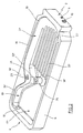
- the microfluidic storage and metering component essentially has one plate-shaped body 1, adjacent to the one end face 2 a - in the Top view dovetail-shaped snap contour 3 ', 3 "in the narrow sides and which is chamfered on the other end face 4 at 5 ', 5 "towards the narrow sides.
- the body 1 is formed from superimposed, plate-shaped bodies with in substantially complementary outer contour, namely from a base body 6, a Reservoir cover 7 and a membrane cover 8.
- the body 1 more precisely the base body 6, has a metering outlet 9 and a mouth 10 of a ventilation duct.
- the body 1, more precisely the base body 6, has one in the end face 4 Filling opening 11, which is shown in FIG. 2.
- the body 1 is adjacent to the snap contour 3 ′′ via a web 12 with a Inscription flag 13 connected, the plate-shaped and perpendicular to the body 1st is aligned. Between the label flag 13 and the adjacent one A narrow side 14 of the body 1 is formed.
- the base body 6 has a recess 15 'in a large-area side, revolves around the bearing surface 16.
- Slats stand from the bottom 17 'of the depression 15' 18 'before, which are directed parallel and in the longitudinal direction of the base body 6.
- the Slats 18 'begin at a first step 19, which is in the recess 15' the end face 2 is formed with the metering opening 9.
- the top On a narrow side of the base body 6 extends starting from the first Gradation 19 a second gradation 22 'in the recess 15', the top (referred 1) is a boundary wall of a capillary riser 22.
- the second gradation 22 'increases slightly from the first gradation 19 Level of the support surface 16 out.
- a boundary wall of a Filling channel 24 is.
- This boundary wall of the filling channel 24 is also related the support surface 16 has a slight inclination, being at the transition to third gradation 22 "the smallest distance and on the front 4 the largest Distance from the support surface 16 has.
- the filling opening 11 opens into the end face 4 directly next to the filling channel 24 the recess 15 '.
- a pin 25 in front of the outer end has a ventilation opening 26 which is guided through a pin 25 and along the opposite side of the base body 6 open ventilation duct 27 (see FIG. 4) is connected to the mouth 10.
- the reservoir cover 7 also has a depression 15 ′′, one Bottom 17 “and is surrounded by a circumferential bearing surface 28 Bottom 17 “project lamellae 18" which are parallel in the longitudinal direction of the reservoir cover 7 are directed.
- the fins 18 “extend from an enlarged area 28 ' the bearing surface 28, which is adjacent to the end face 2. They extend approximately to to the middle of the length of the reservoir lid 7. They end at a distance from the floor 17 "at the level of the contact surface 28. Between the slats 18" and next The two outer lamellae 18 "extend capillary channels 20" which lead to the end face 2 delimited by a paragraph 21 "and open towards the end face 4.
- the contact surface 28 has a widened section 28 "on a narrow side of the reservoir cover 7 in the area next to the slats 18". Adjacent to this, it has an area 28 '' projecting into the area of the recess 15 'free of lamellae. Adjacent to it, it again has a narrower area 28 IV .
- the capillary channels 20 ', 20 “and capillary connections 29 open through an outlet opening 30 into the outlet 30, the outlet opening 30 between the paragraphs 21 ', 21 "(see FIG. 11).
- the part of the bearing surfaces 28 ′′, 28 ′ ′′ delimits the inside of the bearing surfaces 16, 16 'protrudes, the capillary riser 22. This is through a between the bearing surfaces 28 ", 28 '" and steps 22', 22 "formed gap 31 to Reservoir 15 is open, the width of which gradually towards the third gradation 22 " decreases. In the area of the third gradation 22 ′′, the width of the gap 31 is constant (see Fig. 7).
- the part of the contact surfaces 28 '", 28 IV projecting beyond the contact surfaces 16, 16' delimits the filling channel 24, which is also opened towards the reservoir 15 through a lateral gap 32 (cf. FIG. 7).
- the height of the gap 32 increases towards the end wall 4.
- the base body 6 has a circumferential on the other large side Support surface 33.
- a displacement chamber 34 is located within this support surface in the form of a depression which is delimited by a teardrop-shaped wall 35 that ends at the same level as the bearing surface 33.
- the displacement chamber 34 has a central region 34 'of constant height and one with respect to the bearing surface 33, the floor area 34 ′′ which drops steeply, which is the deepest Point is connected to the metering outlet 9. On the other hand has the displacement chamber 34 also a strongly sloping bottom area 34 "', the deepest Point is connected to an input 36 of the displacement chamber 34, which acts as a throttle is trained.
- the passage 23 opens into a connecting channel on this side of the base body 6 37, which is connected at the other end to the entrance 36 and in the central area has a prism-shaped depression 38.
- the connecting channel 37 is also surrounded by a raised wall 39, which ends at the level of the contact surface 33.
- the open section of the ventilation duct 27 is also surrounded by a wall 40, which ends at the level of the contact surface 33. In part, the wall 40 falls with the Walls 35, 39 together.
- the base body 6 has further depressions on the same side that make it more uniform should bring about the wall thicknesses.
- the membrane cover 8 has a substantially flat inside. Near the end face 2 it has a ramp-shaped elevation 41. He has about in the center a prism-shaped elevation 42 in a transparent area close to the long side on a molded pin 43.
- the membrane cover 8 is placed on the contact surfaces 33, 35, 39, 40 of the base body 6 placed and connected to these.
- the ramp-shaped elevation 41 acts as A displacer in the front end region of the displacement chamber 34 and forms at the same time a front stop for positioning the membrane cover 8 on the Basic body 6.
- the prism-shaped elevation 42 engages in the prism-shaped recess 38 and the injection pin 43 into an adjacent recess of the base body 6.
- the membrane cover 8 thus also forms a membrane-shaped cover Displacement chamber 34. It also covers the connecting duct 37 and the ventilation duct 27 from.
- Base body 6, reservoir cover 7 and membrane cover 8 are made by injection molding Made of plastic.
- the plastic can in particular be polycarbonate act. Blackened polycarbonate is used for the base body 6 and for the reservoir cover 7 and the membrane cover 8 at least partially transparent Polycarbonate. This enables the base body 6 and the reservoir cover 7 to be connected and membrane cover 8 by laser welding. Here, a laser beam penetrates the transparent joining part and is absorbed by the opaque joining part, so that there is a strong local heating and thus the parts to be welded.
- the connection of the parts to be joined can in particular also be done by gluing.
- a dimensionally accurate dosing outlet is important for liquid drops or jets.
- a special dimensional accuracy is achieved by drilling the metering outlet or by laser structuring (Imaging of an intense laser beam through a mask onto the workpiece) reachable.
- the storage and dosing component works as follows:
- the liquid to be dosed is entered through the filling opening 11.
- the component is executed as disposable, i.e. as a consumable part, this can done at the manufacturer. But it is also a reusable version of the Component possible in which the filling in particular with the user or a refilling can be done at the manufacturer.
- the component When filling, the component is preferably aligned so that the liquid through the lateral gap 32 initially runs into the filling channel 24 and through this fills the riser channel 22, the capillary channels 20 ', 20 "and the capillary connections. This gradually displaces the air out of the system and makes it bubble-free Filling ensured.
- the reservoir 15 is at most up to the upper edge of the slats 18 ', 18 ".
- the passage 23 and the connecting channel 37 the displacement chamber 34 pre-filled without bubbles.
- the filling opening 11 is closed, for example by permanent Pressing in a glass ball or by inserting a removable plug.
- the outlet 30 at the bottom of the reservoir 15 is at the inlet 36 at the top of the displacement chamber 34 connected via the capillary riser 22. Reservoir 15 and displacement chamber 34 are at about the same level.
- the pressure in the liquid is reduced by the capillary pressure p Kap compared to the ambient pressure and increased by the hydrostatic pressure p h due to the height of the liquid column between the fins 18 ′, 18 ′′.
- Ambient pressure p ⁇ is present at the metering outlet 9 from the outside. Accordingly, liquid does not automatically flow out of the metering outlet if the capillary pressure p Kap is at least as high as the hydrostatic pressure p h . Since the hydrostatic pressure p h is low at the same level due to the arrangement of reservoir 15 and displacement chamber 34, a relatively low capillary pressure p Kap is sufficient to hold the liquid in the system.
- the component For the dosing of liquid, the component is inserted into a dosing device so that the membrane cover 8 with the displacer 34 overlapping Area (preferably under pretension) on an actuator (e.g. a piezo actuator) the dosing device is present and a light barrier for bubble detection of the dosing device is directed from the outside onto the prism 42 of the membrane cover 8. there the component can be released by clamping or snapping it into the metering device held.
- the labeling field 13 is on the outside of an engaging in the gap 14 Housing wall of the dosing device so that the labeling is legible from the outside.
- the dosing device can in particular be a hand-held device.
- the actuator is actuated so that the membrane cover 8 partially in the Displacement chamber 34 is pressed and a defined amount of liquid in the Free jet emerges from the metering opening.
- the throttle in the inlet 36 of the displacement chamber 34 and the metering output 9 are coordinated so that only a relatively small amount of liquid is pushed back into the reservoir 15 and most of the displaced liquid emerges from the metering outlet 9.
- the membrane cover 8 After relief from the actuator, the membrane cover 8 returns due to its elasticity back to its starting position. Due to the negative pressure in the displacement chamber 34 and the capillarity of the riser 22 is liquid from the reservoir 15 in displaced the displacement chamber 34. Sucking in air through the metering outlet 9 is prevented by the capillary pressure of the liquid in the metering outlet 9.
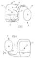
- Figs. 7 and 8 illustrate that the liquid is not in the vent 26 can occur, whether they are completely in the capillary cavities 20 ', 20 ", 29 or in the free area of the reservoir 15 is contained.
- the design of the capillary cavities 20 ', 20 “, 29 of the reservoir also acts 15 disturbing bubbles. 9 and 10, the formation of bubbles 44, for example due to strong vibrations, mainly on the capillary channels 20 ', 20 ".
- the component can be removed from the dosing device and thrown away or be refilled.
Landscapes
- Health & Medical Sciences (AREA)
- Clinical Laboratory Science (AREA)
- Chemical & Material Sciences (AREA)
- Chemical Kinetics & Catalysis (AREA)
- Feeding, Discharge, Calcimining, Fusing, And Gas-Generation Devices (AREA)
- Automatic Analysis And Handling Materials Therefor (AREA)
- Devices For Dispensing Beverages (AREA)
- Physical Or Chemical Processes And Apparatus (AREA)
- Devices For Use In Laboratory Experiments (AREA)
Abstract
- einem Reservoir mit einer Belüftungsöffnung und einem unten angeordneten Ausgang für Flüssigkeit,
- kapillaren Hohlräumen im Reservoir,
- einer zumindest teilweise auf demselben Niveau wie das Reservoir angeordneten Verdrängerkammer mit einem oben angeordneten Eingang und einem unten angeordneten Dosierausgang für Flüssigkeit und
- einem den Ausgang des Reservoirs mit dem Eingang der Verdrängerkammer verbindenden kapillaren Steigkanal.
Description
- einem Reservoir mit einer Belüftungsöffnung und einem unten angeordneten Ausgang für Flüssigkeit,
- kapillaren Hohlräumen im Reservoir,
- einer zumindest teilweise auf demselben Niveau wie das Reservoir angeordneten Verdrängerkammer mit einem oben angeordneten Eingang und einem unten angeordneten Dosierausgang für Flüssigkeit und
- einem den Ausgang des Reservoirs mit dem Eingang der Verdrängerkammer verbindenden kapillaren Steigkanal.
- einem Reservoir mit einer Belüftungsöffnung und einem Ausgang für Flüssigkeit und
- in dem Reservoir angeordneten, zum Ausgang des Reservoirs führenden, parallelen Kapillarkanälen und quer zu den Kapillarkanälen gerichteten, benachbarte Kapillarkanäle miteinander verbindenden und mit dem Ausgang verbundenen Kapillarverbindungen, deren Kapillarität die der Kapillarkanäle übersteigt.
- einem Reservoir mit einer Belüftungsöffnung und einem Ausgang für Flüssigkeit,
- in dem Reservoir angeordneten, zum Ausgang führenden Kapillarkanälen und
- Absätzen an den Enden der Kapillarkanäle, in denen Austrittsöffnungen des Ausgangs für Flüssigkeit angeordnet sind, die einen geringeren Querschnitt als die Kapillarkanäle haben.
- einem Reservoir, das eine Belüftungsöffnung und einen Ausgang für Flüssigkeit aufweist,
- wobei die Belüftungsöffnung an einem zentralen Ort im Reservoir in einem Abstand von Begrenzungswänden des Reservoirs angeordnet ist, so daß bei beliebiger Ausrichtung des mit einer maximal zulässigen Flüssigkeitsmenge gefüllten Reservoirs keine Flüssigkeit durch die Belüftungsöffnung nach außen austritt.
- einem Reservoir mit einer Belüftungsöffnung,
- einer mit dem Reservoir verbundenen Verdrängerkammer mit einem Dosierausgang,
- einem Körper, der Reservoir und Verdrängerkammer umfaßt, und
- einem mit dem Körper über einen Steg verbundenen Beschriftungsfähnchen.
- einem Reservoir mit einer Belüftungsöffnung,
- einer mit dem Reservoir verbundenen Verdrängerkammer mit einem Dosierausgang,
- einem Körper, in dem das Reservoir und die Verdrängerkammer ausgebildet sind und der den Dosierausgang und/oder eine Mündung der Belüftungsöffnung in einer Stirnseite aufweist, und
- eine an der Stirnseite mit dem Dosierausgang ausgebildeten Schnappkontur.
Länge = 23,5 mm, Breite = 10 mm, Höhe = 4,9 mm.
Länge = 19,5 mm, Breite = 14,8 mm, Höhe = ca. 1 mm.
Claims (46)
- Mikrofluidisches Speicher- und Dosierbauteil miteinem Reservoir (15) mit einer Belüftungsöffnung (26) und einem unten angeordneten Ausgang (30) für Flüssigkeit,kapillaren Hohlräumen (20', 20") im Reservoir (15),einer zumindest teilweise auf demselben Niveau wie das Reservoir (15) angeordneten Verdrängerkammer (34) mit einem oben angeordneten Eingang (36) und einem unten angeordneten Dosierausgang (9) für Flüssigkeit undeinem den Ausgang (30) des Reservoirs (15) mit dem Eingang (36) der Verdrängerkammer (34) verbindenden kapillaren Steigkanal (22).
- Bauteil nach Anspruch 1, bei dem das Reservoir (15) und die Verdrängerkammer (34) im wesentlichen auf demselben Niveau angeordnet sind.
- Bauteil nach Anspruch 1 oder 2, bei dem die kapillaren Hohlräume (20', 20") zum Ausgang (30) des Reservoirs (15) führende Kapillarkanäle sind.
- Bauteil nach einem der Ansprüche 1 bis 3, bei dem der Steigkanal (22) über einen Verbindungskanal (37), dem ein Füllstandssensor zugeordnet ist, mit dem Eingang (36) der Verdrängerkammer (34) verbunden ist.
- Bauteil nach Anspruch 4, bei dem der Verbindungskanal (37) zwischen dem höchsten Niveau des Steigkanals (22) und dem Eingang (36) der Verdrängerkammer (34) angeordnet ist.
- Bauteil nach einem der Ansprüche 1 bis 5, bei dem der kapillare Steigkanal (22) seitlich über einen kapillaren Spalt (31) mit dem Reservoir (15) verbunden ist, wobei der kapillare Spalt (31) so ausgelegt ist, daß im Dosierbetrieb Flüssigkeit im wesentlichen vom Ausgang (30) des Reservoirs (15) durch den kapillaren Steigkanal (22) in die Verdrängerkammer (34) strömt und daß bei Anordnung des Bauteils in einem entgegen der Strömungsrichtung im Steigkanal (22) bei Dosierbetrieb gerichteten Zentrifugalfeld Flüssigkeit aus der Verdrängerkammer (34) und dem Steigkanal (22) durch den Spalt (31) in das Reservoir (15) strömt.
- Bauteil nach Anspruch 6, bei dem der kapillare Spalt (31) zumindest teilweise in einem Bereich des Reservoirs (15) oberhalb der kapillaren Hohlräume (20', 20") mündet.
- Bauteil nach Anspruch 6 oder 7, bei dem sich die Kapillarität des Spaltes (31) von unten nach oben vermindert.
- Bauteil nach einem der Ansprüche 1 bis 8, das oben eine mit dem Reservoir (15) verbundene Befüllöffnung (11) aufweist.
- Bauteil nach Anspruch 9, bei dem ein Befüllkanal (24) zwischen der Befüllöffnung (11) und dem Steigkanal (22) angeordnet ist.
- Bauteil nach einem der Ansprüche 1 bis 10, bei dem das Reservoir (15) und die Verdrängerkammer (34) im wesentlichen in parallelen Schichten mindestens eines flachen Körpers (1) angeordnet sind.
- Bauteil nach Anspruch 11, bei dem der Steigkanal (22) und/oder der Befüllkanal (24) im wesentlichen in derselben Schicht wie das Reservoir (15) und/oder der Verbindungskanal (37) im wesentlichen in derselben Schicht wie die Verdrängerkammer (34) angeordnet ist/sind.
- Bauteil nach Anspruch 11 oder 12, bei dem der Steigkanal (22) und der Verbindungskanal (37) oder der Eingang (36) der Verdrängerkammer (34) über einen quergerichteten Durchgang (23) des mindestens einen flachen Körpers (1) miteinander verbunden sind.
- Bauteil nach einem der Ansprüche 11 bis 13, bei dem der Dosierausgang (9) in der einen Stirnseite (2) und/oder die Befüllöffnung (11) in der anderen Stirnseite (4) des mindestens einen flachen Körpers (1) angeordnet ist.
- Bauteil nach einem der Ansprüche 11 bis 14, bei dem das Reservoir (15) und/oder der Steigkanal (22) und/oder der Befüllkanal (24) auf der einen großflächigen Seite eines flachen Grundkörpers (6), die Verdrängerkammer (34) und/oder der Verbindungskanal (37) auf der anderen großflächigen Seite des flachen Grundkörpers (6), der quergerichtete Durchgang (23) in Querrichtung im flachen Grundkörper (6), der Dosierausgang (9) in der einen Stirnseite (2) und/oder die Befüllöffnung (11) in der anderen Stirnseite (4) des flachen Grundkörpers (6) angeordnet sind und der Grundkörper (6) auf der Seite des Reservoirs (15) von einem Reservoirdeckel (7) und auf der Seite der Verdrängerkammer (34) von einem Membrandeckel (8) geschlossen ist.
- Bauteil nach Anspruch 15, bei dem der Reservoirdeckel (7) teilweise das Reservoir (15) und/oder den Steigkanal (22) und/oder den Befüllkanal (24) und/oder der Membrandeckel (8) teilweise die Verdrängerkammer (34) und/oder den Verbindungskanal (37) enthält/enthalten.
- Mikrofluidisches Speicher- und/oder Dosierbauteil, insbesondere nach einem der vorstehenden Ansprüche, miteinem Reservoir (15) mit einer Belüftungsöffnung (26) und einem Ausgang (30) für Flüssigkeit undin dem Reservoir (15) angeordneten, zum Ausgang (30) des Reservoirs (15) führenden, parallelen Kapillarkanälen (20', 20") und quer zu den Kapillarkanälen gerichteten, benachbarte Kapillarkanäle miteinander verbindenden und mit dem Ausgang (30) verbundenen Kapillarverbindungen (29), deren Kapillarität die der Kapillarkanäle (20', 20") übersteigt.
- Bauteil nach Anspruch 17, bei dem der Ausgang (30) des Reservoirs (15) eine Verbindung (22) mit einem Eingang (36) einer Verdrängerkammer (34) mit einem Dosierausgang (9) für Flüssigkeit aufweist.
- Bauteil nach Anspruch 17 oder 18, bei dem die Kapillarkanäle (20', 20") durch parallele Lamellen (18', 18") und die Kapillarverbindungen (29) durch quergerichtete Verbindungsspalte zwischen den Lamellen (18', 18") gebildet sind.
- Bauteil nach Anspruch 19, das einen flachen Grundkörper (6) aufweist, der auf einer Seite von dem Boden (17') einer einen Teil des Reservoirs (15) bildenden Vertiefung (15') vorstehende Lamellen (18') aufweist und einen auf dieser Seite des Grundkörpers (6) angeordneten Reservoirdeckel (7) aufweist, der von dem Boden (17") einer einen zweiten Teil des Reservoirs (15) bildenden Vertiefung (15") vorstehende Lamellen (18") aufweist, wobei die Lamellen (18') des Grundkörpers (6) und die Lamellen (18") des Reservoirdeckels (7) miteinander fluchten und zwischen den Lamellen (18') des Grundkörpers (6) und den Lamellen (18") des Reservoirdeckels (7) die Kapillarverbindungen (29) vorhanden sind.
- Bauteil nach Anspruch 20, bei dem die Kapillarverbindungen (29) in der Trennebene zwischen dem Grundkörper (6) und dem Reservoirdeckel (7) angeordnet sind.
- Mikrofluidisches Speicher- und/oder Dosierbauteil, insbesondere nach einem der vorstehenden Ansprüche, miteinem Reservoir (15) mit einer Belüftungsöffnung (26) und einem Ausgang (30) für Flüssigkeit,dem Reservoir (15) angeordneten, zum Ausgang führenden Kapillarkanälen (20', 20") undAbsätzen (21', 21") an den Enden der Kapillarkanäle (20', 20"), in denen Austrittsöffnungen (30') des Ausgangs (30) für Flüssigkeit angeordnet sind, die einen geringeren Querschnitt als die Kapillarkanäle (20', 20") haben.
- Bauteil nach Anspruch 22, bei dem der Ausgang (30) eine Verbindung (22) mit einem Eingang (36) einer Verdrängerkammer (34) mit einem Dosierausgang (9) für Flüssigkeit aufweist.
- Bauteil nach Anspruch 22 oder 23, bei dem die Kapillarkanäle (20', 20") parallel und/oder geradlinig sind.
- Bauteil nach einem der Ansprüche 22 bis 24, bei dem die Austrittsöffnungen (30') zentral auf die Kapillarkanäle (20', 20") ausgerichtet sind.
- Bauteil nach einem der Ansprüche 22 bis 25, bei dem ein flacher Grundkörper (6) auf einer Seite einen Teil des Reservoirs (15) und ein auf dieser Seite angeordneter Reservoirdeckel (7) einen weiteren Teil des Reservoirs (15) aufweist und die Absätze (21', 21") einen Teil auf dem Grundkörper (6) und einen weiteren Teil auf dem Reservoirdeckel (7) aufweisen.
- Mikrofluidisches Speicher- und/oder Dosierbauteil, insbesondere nach einem der vorstehenden Ansprüche, miteinem Reservoir (15), das eine Belüftungsöffnung (26) und einen Ausgang (9) für Flüssigkeit aufweist,bei die Belüftungsöffnung (26) an einem zentralen Ort im Reservoir (15) in einem Abstand von Begrenzungswänden des Reservoirs angeordnet ist, so daß bei beliebiger Ausrichtung des mit einer maximal zulässigen Flüssigkeitsmenge gefüllten Reservoirs (15) keine Flüssigkeit durch die Belüftungsöffnung (26) nach außen austritt.
- Bauteil nach Anspruch 27, bei dem der Ausgang (30) des Reservoirs (15) eine Verbindung (22) mit dem Eingang (36) einer Verdrängerkammer (34) mit einem Dosierausgang (9) für Flüssigkeit aufweist.
- Bauteil nach Anspruch 27 oder 28, bei dem das Reservoir (15) einen Teil mit kapillaren Hohlräumen (20', 20") und einen von kapillaren Hohlräumen freien Teil aufweist, in dem die Belüftungsöffnung (26) angeordnet ist.
- Bauteil nach einem der Ansprüche 27 bis 29, bei dem der Teil des Reservoirs (15), der von kapillaren Hohlräumen (20', 20") frei ist, etwa dasselbe Flüssigkeitsvolumen aufnehmen kann; wie der Teil des Reservoirs (15), in dem sich die kapillaren Hohlräume befinden.
- Bauteil nach einem der Ansprüche 27 bis 30, bei dem die Belüftungsöffnung (26) eine scharfkantige Umrandung aufweist.
- Bauteil nach einem der Ansprüche 27 bis 31, bei dem das Reservoir (15) zumindest teilweise als Vertiefung (15') in einer Seite eines flachen Grundkörpers (6) ausgebildet ist und vom Boden (17') der Vertiefung ein Zapfen (25) vorsteht, der an seinem freien Ende die Belüftungsöffnung (26) aufweist, von der ein Belüftungskanal (27) durch den Zapfen (25) in den Grundkörper (6) hinein und durch die Wand des Grundkörpers (6) zu einer nach außen führenden Mündung (10) verläuft.
- Bauteil nach Ansprüche 32, bei dem ein Reservoirdeckel (7) auf der Seite des Grundkörpers (6) mit der Belüftungsöffnung (26) angeordnet ist und eine einen weiteren Teil des Reservoirs (15) bildende Vertiefung (15") aufweist.
- Bauteil nach Anspruch 32 oder 33, bei dem die Belüftungsöffnung (26) in der Trennebene des Grundkörpers (6) und des Reservoirdeckels (7) angeordnet ist.
- Bauteil nach einem der Ansprüche 32 bis 34, bei dem der Belüftungskanal (27) den Grundkörper (6) durchquert und auf der anderen Seite des Grundkörpers einen offenen Abschnitt hat.
- Bauteil nach einem der Ansprüche 32 bis 35, bei dem der Belüftungskanal (27) die Mündung (10) in einer Stirnseite (2) des Grundkörpers (6) hat, in der auch der Dosierausgang (9) mündet.
- Mikrofluidisches Speicher- und Dosierbauteil, insbesondere nach einem der vorstehenden Ansprüche miteinem Reservoir (15) mit einer Belüftungsöffnung (26),einer mit dem Reservoir (15) verbundenen Verdrängerkammer (34) mit einem Dosierausgang (9),einem Körper (1), der Reservoir (15) und Verdrängerkammer (34) umfaßt, undeinem mit dem Körper (1) über einen Steg (12) verbundenen Beschriftungsfähnchen (13).
- Bauteil nach Anspruch 37, bei dem der Körper (1) und das Beschriftungsfähnchen (13) plattenförmig sind.
- Bauteil nach Anspruch 37 oder 38, bei dem der Körper (1) und das Beschriftungsfähnchen (13) senkrecht zueinander ausgerichtet sind.
- Bauteil nach einem der Ansprüche 37 bis 39, bei dem zwischen Beschriftungsfähnchen (13) und Körper (1) ein Schlitz (14) zur Aufnahme eines Gehäuseabschnittes eines das Bauteil aufnehmenden Gerätes vorhanden ist.
- Mikrofluidisches Speicher- und Dosierbauteil, insbesondere nach einem der vorstehenden Ansprüche, miteinem Reservoir (15) mit einer Belüftungsöffnung (26),einer mit dem Reservoir (15) verbundenen Verdrängerkammer (34) mit einem Dosierausgang (9),einem Körper (1), in dem das Reservoir (15) und die Verdrängerkammer (34) ausgebildet sind und der den Dosierausgang (9) und/oder eine Mündung (10) der Belüftungsöffnung (26) in einer Stirnseite (2) aufweist, undeiner an der Stirnseite (2) mit dem Dosierausgang ausgebildeten Schnappkontur (3', 3").
- Bauteil nach Anspruch 41, bei dem die Schnappkontur (3'. 3") schwalbenschwanzförmig ist.
- Bauteil nach Anspruch 41 oder 42, bei dem die Schnappkontur (3', 3") lösbar mit einer Verschlußkappe zum Verschließen der Dosieröffnung (9) und/oder der Mündung (10) oder mit einer Zielhilfe zum Ausrichten des Dosierausganges (9) auf ein Objekt verbunden ist.
- Bauteil nach einem der Ansprüche 1 bis 43, bei dem der Eingang (36) der Verdrängerkammer (34) eine Drossel aufweist und/oder der Dosierausgang (9) eine Düse aufweist.
- Bauteil nach einem der Ansprüche 1 bis 44, das lösbar mit einer Dosiervorrichtung verbunden ist, die einen auf eine Wand (8) der Verdrängerkammer (34) des Bauteils einwirkenden Aktuator hat, um die Wand zu verlagern und in der Verdrängerkammer (34) enthaltene Flüssigkeit zu verdrängen.
- Bauteil nach einem der Ansprüche 1 bis 45, das lösbar mit einer Dosiervorrichtung verbunden ist, die einen Füllstandssensor zum Abtasten des Füllstands im Verbindungskanal (37) aufweist.
Applications Claiming Priority (2)
| Application Number | Priority Date | Filing Date | Title |
|---|---|---|---|
| DE10123259A DE10123259A1 (de) | 2001-05-12 | 2001-05-12 | Mikrofluidisches Speicher- und/oder Dosierbauteil |
| DE10123259 | 2001-05-12 |
Publications (3)
| Publication Number | Publication Date |
|---|---|
| EP1256543A2 true EP1256543A2 (de) | 2002-11-13 |
| EP1256543A3 EP1256543A3 (de) | 2005-10-12 |
| EP1256543B1 EP1256543B1 (de) | 2011-11-30 |
Family
ID=7684631
Family Applications (1)
| Application Number | Title | Priority Date | Filing Date |
|---|---|---|---|
| EP02008129A Expired - Lifetime EP1256543B1 (de) | 2001-05-12 | 2002-04-11 | Mikrofluidisches Speicher- und/oder Dosierbauteil |
Country Status (4)
| Country | Link |
|---|---|
| US (1) | US7067086B2 (de) |
| EP (1) | EP1256543B1 (de) |
| AT (1) | ATE535493T1 (de) |
| DE (1) | DE10123259A1 (de) |
Families Citing this family (27)
| Publication number | Priority date | Publication date | Assignee | Title |
|---|---|---|---|---|
| US8071384B2 (en) | 1997-12-22 | 2011-12-06 | Roche Diagnostics Operations, Inc. | Control and calibration solutions and methods for their use |
| US8148164B2 (en) | 2003-06-20 | 2012-04-03 | Roche Diagnostics Operations, Inc. | System and method for determining the concentration of an analyte in a sample fluid |
| US7645421B2 (en) | 2003-06-20 | 2010-01-12 | Roche Diagnostics Operations, Inc. | System and method for coding information on a biosensor test strip |
| US7604721B2 (en) | 2003-06-20 | 2009-10-20 | Roche Diagnostics Operations, Inc. | System and method for coding information on a biosensor test strip |
| US7718439B2 (en) | 2003-06-20 | 2010-05-18 | Roche Diagnostics Operations, Inc. | System and method for coding information on a biosensor test strip |
| US7597793B2 (en) | 2003-06-20 | 2009-10-06 | Roche Operations Ltd. | System and method for analyte measurement employing maximum dosing time delay |
| US7645373B2 (en) | 2003-06-20 | 2010-01-12 | Roche Diagnostic Operations, Inc. | System and method for coding information on a biosensor test strip |
| US7452457B2 (en) | 2003-06-20 | 2008-11-18 | Roche Diagnostics Operations, Inc. | System and method for analyte measurement using dose sufficiency electrodes |
| US8206565B2 (en) | 2003-06-20 | 2012-06-26 | Roche Diagnostics Operation, Inc. | System and method for coding information on a biosensor test strip |
| US8058077B2 (en) | 2003-06-20 | 2011-11-15 | Roche Diagnostics Operations, Inc. | Method for coding information on a biosensor test strip |
| US7556723B2 (en) | 2004-06-18 | 2009-07-07 | Roche Diagnostics Operations, Inc. | Electrode design for biosensor |
| US7569126B2 (en) | 2004-06-18 | 2009-08-04 | Roche Diagnostics Operations, Inc. | System and method for quality assurance of a biosensor test strip |
| EP1878802A1 (de) * | 2006-07-14 | 2008-01-16 | Roche Diagnostics GmbH | Einwegvorrichtung zur Analyse einer Nukleinsäure enthaltenden Probe mit einem Amplifikation-Apparatus |
| EP1878497A1 (de) * | 2006-07-14 | 2008-01-16 | Roche Diagnostics GmbH | Einwegartikel zur Analyse einer flüssigen probe durch Vervielfältigung von Nukleinsäuren |
| US8246829B2 (en) * | 2007-05-10 | 2012-08-21 | O'regan Jr Patrick T | Systems and methods for water treatment and remediation |
| FR2928632B1 (fr) * | 2008-03-11 | 2012-06-01 | Imagene | Contenant destine a recevoir et conserver du materiel biologique, notamment de l'adn |
| US12090480B2 (en) * | 2008-09-23 | 2024-09-17 | Bio-Rad Laboratories, Inc. | Partition-based method of analysis |
| US12162008B2 (en) | 2008-09-23 | 2024-12-10 | Bio-Rad Laboratories, Inc. | Partition-based method of analysis |
| AU2009320033A1 (en) * | 2008-11-02 | 2010-06-03 | Nobska Technologies, Inc | Water treatment systems with communications network links and methods |
| DE102009018021B4 (de) | 2009-04-18 | 2013-09-05 | Helmholtz-Zentrum Berlin Für Materialien Und Energie Gmbh | Mikrodosiersystem mit einem gepulsten Laser |
| US12097495B2 (en) | 2011-02-18 | 2024-09-24 | Bio-Rad Laboratories, Inc. | Methods and compositions for detecting genetic material |
| US11430279B2 (en) * | 2012-05-09 | 2022-08-30 | Wisconsin Alumni Research Foundation | Functionalized microfluidic device and method |
| USD700354S1 (en) * | 2012-06-04 | 2014-02-25 | Unisense Fertilitech A/S | Embryo slide culture dish |
| US10076751B2 (en) | 2013-12-30 | 2018-09-18 | General Electric Company | Systems and methods for reagent storage |
| US9399216B2 (en) | 2013-12-30 | 2016-07-26 | General Electric Company | Fluid transport in microfluidic applications with sensors for detecting fluid presence and pressure |
| US11007525B2 (en) | 2015-01-30 | 2021-05-18 | Hewlett-Packard Development Company, L.P. | Vented microfluidic reservoirs |
| CN119098234B (zh) * | 2024-09-25 | 2025-09-16 | 浙江大学 | 用于电化学发光免疫分析检测的微流控分析装置及方法 |
Family Cites Families (11)
| Publication number | Priority date | Publication date | Assignee | Title |
|---|---|---|---|---|
| US4618476A (en) * | 1984-02-10 | 1986-10-21 | Eastman Kodak Company | Capillary transport device having speed and meniscus control means |
| DE4202561A1 (de) * | 1992-01-30 | 1993-08-05 | Boehringer Mannheim Gmbh | Vorrichtung zum dosierten zufuehren einer analysefluessigkeit |
| DE4443290A1 (de) * | 1994-12-06 | 1996-06-13 | Eastman Kodak Co | Vorrichtung zur Flüssigkeitsversorgung einer Mikrodosiervorrichtung |
| JPH08219956A (ja) * | 1995-02-17 | 1996-08-30 | Hitachi Koki Co Ltd | ピペット及びその使用方法 |
| US6063589A (en) * | 1997-05-23 | 2000-05-16 | Gamera Bioscience Corporation | Devices and methods for using centripetal acceleration to drive fluid movement on a microfluidics system |
| US5916522A (en) * | 1997-08-07 | 1999-06-29 | Careside, Inc. | Electrochemical analytical cartridge |
| DE19737173B4 (de) * | 1997-08-26 | 2007-04-05 | Eppendorf Ag | Mikrodosiersystem |
| DE19802368C1 (de) * | 1998-01-22 | 1999-08-05 | Hahn Schickard Ges | Mikrodosiervorrichtung |
| US6184040B1 (en) * | 1998-02-12 | 2001-02-06 | Polaroid Corporation | Diagnostic assay system and method |
| WO2001055701A1 (en) * | 2000-01-31 | 2001-08-02 | Board Of Regents, The University Of Texas System | System and method for the analysis of bodily fluids |
| DE10022398B4 (de) * | 2000-04-28 | 2011-03-17 | Eppendorf Ag | Gaspolster-Mikrodosiersystem |
-
2001
- 2001-05-12 DE DE10123259A patent/DE10123259A1/de not_active Withdrawn
-
2002
- 2002-04-11 AT AT02008129T patent/ATE535493T1/de active
- 2002-04-11 EP EP02008129A patent/EP1256543B1/de not_active Expired - Lifetime
- 2002-05-09 US US10/143,400 patent/US7067086B2/en not_active Expired - Fee Related
Also Published As
| Publication number | Publication date |
|---|---|
| ATE535493T1 (de) | 2011-12-15 |
| US20020168298A1 (en) | 2002-11-14 |
| DE10123259A1 (de) | 2002-11-21 |
| US7067086B2 (en) | 2006-06-27 |
| EP1256543B1 (de) | 2011-11-30 |
| EP1256543A3 (de) | 2005-10-12 |
Similar Documents
| Publication | Publication Date | Title |
|---|---|---|
| EP1256543B1 (de) | Mikrofluidisches Speicher- und/oder Dosierbauteil | |
| US20230371865A1 (en) | Devices, Systems and Methods for Gravity-Enhanced Microfluidic Collection, Handling and Transferring of Fluids | |
| EP1150105B1 (de) | Gaspolster-Mikrodosiersystem | |
| EP1049538B1 (de) | Mikrodosiervorrichtung | |
| US10779757B2 (en) | Devices, systems and methods for gravity-enhanced microfluidic collection, handling and transferring of fluids | |
| DE60300624T2 (de) | Tintenbehälter und Tintenstrahldrucker | |
| DE10052819B4 (de) | Pipettensystem und Pipettenarray sowie Verfahren zum Befüllen eines Pipettensystems | |
| DE102016122056B4 (de) | Mikrofluidisches System zur Aufnahme, Abgabe und Bewegung von Fluiden | |
| DE60131735T2 (de) | Vorrichtung zur abgabe von genau kontrollierten kleinen flüssigkeitsmengen | |
| EP2308589B9 (de) | Mikrofluidische struktur | |
| DE19933458A1 (de) | Einrichtung zum Handhaben von Flüssigkeitsproben, System zum Handhaben von Flüssigkeitsproben und Verfahren zum Herstellen der Einrichtung | |
| WO2019219844A1 (de) | Fluidisches system zur aufnahme, abgabe und bewegung von flüssigkeiten, verfahren zur verarbeitung von fluiden in einem fluidischen system | |
| WO1999010099A1 (de) | Mikrodosiersystem | |
| EP2988871B1 (de) | Verfahren zur befüllung einer mikrofluidischen vorrichtung mittels eines dispensiersystems, und entsprechendes testsystem | |
| EP2406495B1 (de) | Pumpe mit einer filteranordnung | |
| WO2011000738A1 (de) | Ventil | |
| EP2623203B1 (de) | Kapillardispenser | |
| DE112005000445T5 (de) | Mikrochemisches System | |
| DE202009001744U1 (de) | Tintenkartusche | |
| EP2729251B1 (de) | Mikrofluidische struktur mit vertiefungen | |
| EP0187167A1 (de) | Dosiergerät für Flüssigkeiten | |
| DE102008016549A1 (de) | Dosiervorrichtung für kontaktfreie Flüssigkeitsabgabe | |
| EP2112544B9 (de) | Fluidische Anzeigevorrichtung mit pixelintegrierter Rückführung des Fluids | |
| WO2000062932A2 (de) | VERFAHREN UND VORRICHTUNG ZUR DOSIERTEN AUSGABE VON FLÜSSIGKEITSMENGEN IM BEREICH VON 0,1 NL BIS 100 νL | |
| DE10346899B4 (de) | Tintenstrahlkassette mit Luftverwaltungssystem |
Legal Events
| Date | Code | Title | Description |
|---|---|---|---|
| PUAI | Public reference made under article 153(3) epc to a published international application that has entered the european phase |
Free format text: ORIGINAL CODE: 0009012 |
|
| AK | Designated contracting states |
Kind code of ref document: A2 Designated state(s): AT BE CH CY DE DK ES FI FR GB GR IE IT LI LU MC NL PT SE TR |
|
| AX | Request for extension of the european patent |
Free format text: AL;LT;LV;MK;RO;SI |
|
| PUAL | Search report despatched |
Free format text: ORIGINAL CODE: 0009013 |
|
| AK | Designated contracting states |
Kind code of ref document: A3 Designated state(s): AT BE CH CY DE DK ES FI FR GB GR IE IT LI LU MC NL PT SE TR |
|
| AX | Request for extension of the european patent |
Extension state: AL LT LV MK RO SI |
|
| 17P | Request for examination filed |
Effective date: 20051028 |
|
| AKX | Designation fees paid |
Designated state(s): AT BE CH CY DE DK ES FI FR GB GR IE IT LI LU MC NL PT SE TR |
|
| 17Q | First examination report despatched |
Effective date: 20080721 |
|
| GRAP | Despatch of communication of intention to grant a patent |
Free format text: ORIGINAL CODE: EPIDOSNIGR1 |
|
| GRAS | Grant fee paid |
Free format text: ORIGINAL CODE: EPIDOSNIGR3 |
|
| GRAA | (expected) grant |
Free format text: ORIGINAL CODE: 0009210 |
|
| AK | Designated contracting states |
Kind code of ref document: B1 Designated state(s): AT BE CH CY DE DK ES FI FR GB GR IE IT LI LU MC NL PT SE TR |
|
| REG | Reference to a national code |
Ref country code: GB Ref legal event code: FG4D Free format text: NOT ENGLISH Ref country code: CH Ref legal event code: EP Ref country code: CH Ref legal event code: NV Representative=s name: BOHEST AG |
|
| REG | Reference to a national code |
Ref country code: IE Ref legal event code: FG4D Free format text: LANGUAGE OF EP DOCUMENT: GERMAN |
|
| REG | Reference to a national code |
Ref country code: DE Ref legal event code: R096 Ref document number: 50215299 Country of ref document: DE Effective date: 20120202 |
|
| REG | Reference to a national code |
Ref country code: NL Ref legal event code: VDEP Effective date: 20111130 |
|
| PG25 | Lapsed in a contracting state [announced via postgrant information from national office to epo] |
Ref country code: SE Free format text: LAPSE BECAUSE OF FAILURE TO SUBMIT A TRANSLATION OF THE DESCRIPTION OR TO PAY THE FEE WITHIN THE PRESCRIBED TIME-LIMIT Effective date: 20111130 Ref country code: NL Free format text: LAPSE BECAUSE OF FAILURE TO SUBMIT A TRANSLATION OF THE DESCRIPTION OR TO PAY THE FEE WITHIN THE PRESCRIBED TIME-LIMIT Effective date: 20111130 Ref country code: GR Free format text: LAPSE BECAUSE OF FAILURE TO SUBMIT A TRANSLATION OF THE DESCRIPTION OR TO PAY THE FEE WITHIN THE PRESCRIBED TIME-LIMIT Effective date: 20120301 Ref country code: PT Free format text: LAPSE BECAUSE OF FAILURE TO SUBMIT A TRANSLATION OF THE DESCRIPTION OR TO PAY THE FEE WITHIN THE PRESCRIBED TIME-LIMIT Effective date: 20120330 |
|
| REG | Reference to a national code |
Ref country code: IE Ref legal event code: FD4D |
|
| PG25 | Lapsed in a contracting state [announced via postgrant information from national office to epo] |
Ref country code: CY Free format text: LAPSE BECAUSE OF FAILURE TO SUBMIT A TRANSLATION OF THE DESCRIPTION OR TO PAY THE FEE WITHIN THE PRESCRIBED TIME-LIMIT Effective date: 20111130 |
|
| PG25 | Lapsed in a contracting state [announced via postgrant information from national office to epo] |
Ref country code: IE Free format text: LAPSE BECAUSE OF FAILURE TO SUBMIT A TRANSLATION OF THE DESCRIPTION OR TO PAY THE FEE WITHIN THE PRESCRIBED TIME-LIMIT Effective date: 20111130 Ref country code: DK Free format text: LAPSE BECAUSE OF FAILURE TO SUBMIT A TRANSLATION OF THE DESCRIPTION OR TO PAY THE FEE WITHIN THE PRESCRIBED TIME-LIMIT Effective date: 20111130 |
|
| PG25 | Lapsed in a contracting state [announced via postgrant information from national office to epo] |
Ref country code: IT Free format text: LAPSE BECAUSE OF FAILURE TO SUBMIT A TRANSLATION OF THE DESCRIPTION OR TO PAY THE FEE WITHIN THE PRESCRIBED TIME-LIMIT Effective date: 20111130 |
|
| PLBE | No opposition filed within time limit |
Free format text: ORIGINAL CODE: 0009261 |
|
| STAA | Information on the status of an ep patent application or granted ep patent |
Free format text: STATUS: NO OPPOSITION FILED WITHIN TIME LIMIT |
|
| BERE | Be: lapsed |
Owner name: EPPENDORF A.G. Effective date: 20120430 |
|
| 26N | No opposition filed |
Effective date: 20120831 |
|
| PG25 | Lapsed in a contracting state [announced via postgrant information from national office to epo] |
Ref country code: MC Free format text: LAPSE BECAUSE OF NON-PAYMENT OF DUE FEES Effective date: 20120430 |
|
| REG | Reference to a national code |
Ref country code: DE Ref legal event code: R097 Ref document number: 50215299 Country of ref document: DE Effective date: 20120831 |
|
| PG25 | Lapsed in a contracting state [announced via postgrant information from national office to epo] |
Ref country code: BE Free format text: LAPSE BECAUSE OF NON-PAYMENT OF DUE FEES Effective date: 20120430 |
|
| PG25 | Lapsed in a contracting state [announced via postgrant information from national office to epo] |
Ref country code: ES Free format text: LAPSE BECAUSE OF FAILURE TO SUBMIT A TRANSLATION OF THE DESCRIPTION OR TO PAY THE FEE WITHIN THE PRESCRIBED TIME-LIMIT Effective date: 20120311 |
|
| REG | Reference to a national code |
Ref country code: AT Ref legal event code: MM01 Ref document number: 535493 Country of ref document: AT Kind code of ref document: T Effective date: 20120411 |
|
| PG25 | Lapsed in a contracting state [announced via postgrant information from national office to epo] |
Ref country code: FI Free format text: LAPSE BECAUSE OF FAILURE TO SUBMIT A TRANSLATION OF THE DESCRIPTION OR TO PAY THE FEE WITHIN THE PRESCRIBED TIME-LIMIT Effective date: 20111130 |
|
| PG25 | Lapsed in a contracting state [announced via postgrant information from national office to epo] |
Ref country code: AT Free format text: LAPSE BECAUSE OF NON-PAYMENT OF DUE FEES Effective date: 20120411 |
|
| PG25 | Lapsed in a contracting state [announced via postgrant information from national office to epo] |
Ref country code: TR Free format text: LAPSE BECAUSE OF FAILURE TO SUBMIT A TRANSLATION OF THE DESCRIPTION OR TO PAY THE FEE WITHIN THE PRESCRIBED TIME-LIMIT Effective date: 20111130 |
|
| PG25 | Lapsed in a contracting state [announced via postgrant information from national office to epo] |
Ref country code: LU Free format text: LAPSE BECAUSE OF NON-PAYMENT OF DUE FEES Effective date: 20120411 |
|
| REG | Reference to a national code |
Ref country code: CH Ref legal event code: PCAR Free format text: NEW ADDRESS: HOLBEINSTRASSE 36-38, 4051 BASEL (CH) |
|
| REG | Reference to a national code |
Ref country code: FR Ref legal event code: PLFP Year of fee payment: 14 |
|
| PGFP | Annual fee paid to national office [announced via postgrant information from national office to epo] |
Ref country code: CH Payment date: 20150420 Year of fee payment: 14 Ref country code: DE Payment date: 20150421 Year of fee payment: 14 Ref country code: GB Payment date: 20150420 Year of fee payment: 14 |
|
| PGFP | Annual fee paid to national office [announced via postgrant information from national office to epo] |
Ref country code: FR Payment date: 20150421 Year of fee payment: 14 |
|
| REG | Reference to a national code |
Ref country code: DE Ref legal event code: R119 Ref document number: 50215299 Country of ref document: DE |
|
| REG | Reference to a national code |
Ref country code: CH Ref legal event code: PL |
|
| GBPC | Gb: european patent ceased through non-payment of renewal fee |
Effective date: 20160411 |
|
| REG | Reference to a national code |
Ref country code: FR Ref legal event code: ST Effective date: 20161230 |
|
| PG25 | Lapsed in a contracting state [announced via postgrant information from national office to epo] |
Ref country code: DE Free format text: LAPSE BECAUSE OF NON-PAYMENT OF DUE FEES Effective date: 20161101 Ref country code: GB Free format text: LAPSE BECAUSE OF NON-PAYMENT OF DUE FEES Effective date: 20160411 Ref country code: CH Free format text: LAPSE BECAUSE OF NON-PAYMENT OF DUE FEES Effective date: 20160430 Ref country code: LI Free format text: LAPSE BECAUSE OF NON-PAYMENT OF DUE FEES Effective date: 20160430 Ref country code: FR Free format text: LAPSE BECAUSE OF NON-PAYMENT OF DUE FEES Effective date: 20160502 |