EP1256732A1 - Structure de support pour axe rotatif d'un moteur ou générateur - Google Patents
Structure de support pour axe rotatif d'un moteur ou générateur Download PDFInfo
- Publication number
- EP1256732A1 EP1256732A1 EP02007651A EP02007651A EP1256732A1 EP 1256732 A1 EP1256732 A1 EP 1256732A1 EP 02007651 A EP02007651 A EP 02007651A EP 02007651 A EP02007651 A EP 02007651A EP 1256732 A1 EP1256732 A1 EP 1256732A1
- Authority
- EP
- European Patent Office
- Prior art keywords
- rotation shaft
- rotating body
- generator
- engine
- support structure
- Prior art date
- Legal status (The legal status is an assumption and is not a legal conclusion. Google has not performed a legal analysis and makes no representation as to the accuracy of the status listed.)
- Granted
Links
- 230000001133 acceleration Effects 0.000 claims description 10
- 238000006073 displacement reaction Methods 0.000 claims description 8
- 238000002485 combustion reaction Methods 0.000 claims description 5
- 230000003534 oscillatory effect Effects 0.000 claims description 3
- 239000000314 lubricant Substances 0.000 claims 1
- 230000008602 contraction Effects 0.000 abstract description 2
- 239000003921 oil Substances 0.000 description 4
- 238000010586 diagram Methods 0.000 description 3
- 239000010687 lubricating oil Substances 0.000 description 2
- 238000005461 lubrication Methods 0.000 description 2
- 230000035939 shock Effects 0.000 description 2
- 230000006835 compression Effects 0.000 description 1
- 238000007906 compression Methods 0.000 description 1
- 238000000034 method Methods 0.000 description 1
- 238000012986 modification Methods 0.000 description 1
- 230000004048 modification Effects 0.000 description 1
Images



Classifications
-
- H—ELECTRICITY
- H02—GENERATION; CONVERSION OR DISTRIBUTION OF ELECTRIC POWER
- H02K—DYNAMO-ELECTRIC MACHINES
- H02K5/00—Casings; Enclosures; Supports
- H02K5/04—Casings or enclosures characterised by the shape, form or construction thereof
- H02K5/16—Means for supporting bearings, e.g. insulating supports or means for fitting bearings in the bearing-shields
- H02K5/173—Means for supporting bearings, e.g. insulating supports or means for fitting bearings in the bearing-shields using bearings with rolling contact, e.g. ball bearings
- H02K5/1732—Means for supporting bearings, e.g. insulating supports or means for fitting bearings in the bearing-shields using bearings with rolling contact, e.g. ball bearings radially supporting the rotary shaft at both ends of the rotor
-
- F—MECHANICAL ENGINEERING; LIGHTING; HEATING; WEAPONS; BLASTING
- F16—ENGINEERING ELEMENTS AND UNITS; GENERAL MEASURES FOR PRODUCING AND MAINTAINING EFFECTIVE FUNCTIONING OF MACHINES OR INSTALLATIONS; THERMAL INSULATION IN GENERAL
- F16C—SHAFTS; FLEXIBLE SHAFTS; ELEMENTS OR CRANKSHAFT MECHANISMS; ROTARY BODIES OTHER THAN GEARING ELEMENTS; BEARINGS
- F16C25/00—Bearings for exclusively rotary movement adjustable for wear or play
- F16C25/06—Ball or roller bearings
- F16C25/08—Ball or roller bearings self-adjusting
- F16C25/083—Ball or roller bearings self-adjusting with resilient means acting axially on a race ring to preload the bearing
-
- F—MECHANICAL ENGINEERING; LIGHTING; HEATING; WEAPONS; BLASTING
- F16—ENGINEERING ELEMENTS AND UNITS; GENERAL MEASURES FOR PRODUCING AND MAINTAINING EFFECTIVE FUNCTIONING OF MACHINES OR INSTALLATIONS; THERMAL INSULATION IN GENERAL
- F16C—SHAFTS; FLEXIBLE SHAFTS; ELEMENTS OR CRANKSHAFT MECHANISMS; ROTARY BODIES OTHER THAN GEARING ELEMENTS; BEARINGS
- F16C19/00—Bearings with rolling contact, for exclusively rotary movement
- F16C19/54—Systems consisting of a plurality of bearings with rolling friction
-
- F—MECHANICAL ENGINEERING; LIGHTING; HEATING; WEAPONS; BLASTING
- F16—ENGINEERING ELEMENTS AND UNITS; GENERAL MEASURES FOR PRODUCING AND MAINTAINING EFFECTIVE FUNCTIONING OF MACHINES OR INSTALLATIONS; THERMAL INSULATION IN GENERAL
- F16C—SHAFTS; FLEXIBLE SHAFTS; ELEMENTS OR CRANKSHAFT MECHANISMS; ROTARY BODIES OTHER THAN GEARING ELEMENTS; BEARINGS
- F16C2380/00—Electrical apparatus
- F16C2380/26—Dynamo-electric machines or combinations therewith, e.g. electro-motors and generators
-
- F—MECHANICAL ENGINEERING; LIGHTING; HEATING; WEAPONS; BLASTING
- F16—ENGINEERING ELEMENTS AND UNITS; GENERAL MEASURES FOR PRODUCING AND MAINTAINING EFFECTIVE FUNCTIONING OF MACHINES OR INSTALLATIONS; THERMAL INSULATION IN GENERAL
- F16C—SHAFTS; FLEXIBLE SHAFTS; ELEMENTS OR CRANKSHAFT MECHANISMS; ROTARY BODIES OTHER THAN GEARING ELEMENTS; BEARINGS
- F16C27/00—Elastic or yielding bearings or bearing supports, for exclusively rotary movement
- F16C27/08—Elastic or yielding bearings or bearing supports, for exclusively rotary movement primarily for axial load, e.g. for vertically-arranged shafts
Definitions
- the rotation shaft moves beyond the extension-contraction range of the pressurizing members when a large deflection is applied.
- the pressurizing member no longer pressurizes the bearing at one end. When this occurs, a shock is applied to the bearings and the bearings wear down early.
- this invention provides a support structure of a rotation shaft of a motor/generator connected to an external device.
- the rotation shaft has two ends.
- the structure comprises a pair of bearings respectively fitted to the ends of the rotation shaft, each of the bearings having an end face perpendicular to the rotation shaft, a housing having bearing fitting parts that respectively support the bearings, the fitting parts allowing a displacement of the bearings in an axial direction of the rotation shaft, and a pair of pressurizing members each of which is disposed between the end face of each of the bearings and the housing.
- An effective gap between the end face of each of the bearings and the housing is set to be larger than a maximum amplitude of vibration of the rotation shaft in the axial direction caused by the external device.
- Fig. 2 is a schematic diagram of a lubricating oil system with the motor/generator according to this invention.
- a rotation shaft support structure of a motor/generator 1 comprises a housing 9, a rotation shaft 2, a rotating body 3, plate springs 15, 17, and ball bearings 5, 7.
- the rotation shaft support structure has apparent gaps M in the axial direction of rotation shaft between the ball bearings 5, 7 and the housing 9. However, the actual sliding distances of the ball bearings 5, 7 are less than the apparent gaps M.
- the effective gaps L which show the sliding distances of the ball bearings 5, 7 are expressed by the following expression.
- the effective gaps L are set to a value larger than the maximum amplitude of the deflection applied to the motor/generator 1.
- the effective gaps L supply distances for the plate springs 15, 17 to absorb the vibration energy when the rotation shaft 2 displaces in the axial direction. Therefore, this effective gaps L are the gaps required to prevent the end faces of the ball bearings 5, 7 from colliding with the housing 9.
- the ball bearings 5, 7 suffers wear due to shocks. Therefore, the apparent gaps M must be set to a value which does not exceed the thickness of the plate springs 15, 17 when fully extended so that this phenomenon does not occur.
- a platform 25 mounts the motor/generator 1 and a pump unit 26 comprising a motor 20 and a pump 21.
- the pump unit 26 is connected to the motor/generator 1 via an oil pipe 22 to supply lubrication oil to the bearings 5, 7 of the motor/generator 1.
- the peak amplitude calculated by the above equation shows the peak amplitude of a vertical component to the rotation shaft 2.
- the peak amplitude of the perpendicular component may be regarded as the peak amplitude value in the axial direction of rotation shaft.
- this invention can also be applied to a lubricating oil device wherein the pump unit 26 is arranged vertically.
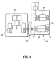
- This embodiment relates to the setting of the effective gaps L of a generator 35 comprising the rotation shaft support structure according to this invention.
- the generator 35 is provided as a part of a hybrid system for a vehicle.
- This hybrid system comprises a four-cylinder engine 30, a damper housing 31, and a hybrid unit 32 comprising the generator 35 and a motor 36.
- the generator 35 supports a rotor 37 with the rotation shaft support structure according to this invention.
- the vibratory acceleration relative to time A ( T ) is expressed by the following expression.
- a (T) P ⁇ 9.8 ⁇ sin ⁇ 2 ⁇ ( R / 60) ⁇ 2 ⁇ ⁇ T ⁇
- the peak amplitude when the engine rotation speed is 700rpm is 0.46mm
- the peak amplitude when the engine rotation speed is 6500rpm is 0.11mm.
- the rotation shaft support structure of this invention is generally referred to as a spring-mass system, and has a characteristic which induces resonance with a certain resonance frequency.
- the ball bearings 5, 7 may collide with the housing 9.
- the stiffness of the plate springs 15, 17 is set as following steps.
- the stiffness of the plate springs 15, 17 is determined to make the resonance frequency H of the rotation shaft support structure out of the calculated vibration frequency range. If the idle rotation speed is Nei, the calculation equation for the stiffness of the plate springs 15, 17 is expressed by the following expression. ( Nei / 60) ⁇ (N / 2) ⁇ (K / Mb ) 1/2
- the stiffness of the plate springs 15, 17 is determined to make the resonance frequency occur below the idle rotation speed of 700rpm of the engine 30.
Landscapes
- Engineering & Computer Science (AREA)
- General Engineering & Computer Science (AREA)
- Mechanical Engineering (AREA)
- Power Engineering (AREA)
- Motor Or Generator Frames (AREA)
- Rolling Contact Bearings (AREA)
- Support Of The Bearing (AREA)
Applications Claiming Priority (2)
| Application Number | Priority Date | Filing Date | Title |
|---|---|---|---|
| JP2001141790A JP4154134B2 (ja) | 2001-05-11 | 2001-05-11 | 回転電機の軸支持構造 |
| JP2001141790 | 2001-05-11 |
Publications (2)
| Publication Number | Publication Date |
|---|---|
| EP1256732A1 true EP1256732A1 (fr) | 2002-11-13 |
| EP1256732B1 EP1256732B1 (fr) | 2005-08-17 |
Family
ID=18988189
Family Applications (1)
| Application Number | Title | Priority Date | Filing Date |
|---|---|---|---|
| EP02007651A Expired - Lifetime EP1256732B1 (fr) | 2001-05-11 | 2002-04-04 | Structure de support pour axe rotatif d'un moteur ou générateur |
Country Status (4)
| Country | Link |
|---|---|
| US (1) | US6848831B2 (fr) |
| EP (1) | EP1256732B1 (fr) |
| JP (1) | JP4154134B2 (fr) |
| DE (1) | DE60205524T2 (fr) |
Cited By (4)
| Publication number | Priority date | Publication date | Assignee | Title |
|---|---|---|---|---|
| WO2004107533A1 (fr) * | 2003-05-28 | 2004-12-09 | Robert Bosch Gmbh | Machine electrique |
| CN103683633A (zh) * | 2012-08-29 | 2014-03-26 | 现代摩比斯株式会社 | 转子偏心防止结构 |
| WO2014075669A1 (fr) * | 2012-11-19 | 2014-05-22 | Schaeffler Technologies AG & Co. KG | Système de roulement pour le montage d'une partie d'arbre, en particulier dans un moteur à induit interne |
| WO2022089684A1 (fr) * | 2020-10-28 | 2022-05-05 | Schaeffler Technologies AG & Co. KG | Machine électrique, procédé de fabrication d'une machine électrique et chaîne cinématique électrique |
Families Citing this family (11)
| Publication number | Priority date | Publication date | Assignee | Title |
|---|---|---|---|---|
| US7327059B2 (en) | 2004-03-22 | 2008-02-05 | General Motors Corporation | Integrated motor bearing springs for hybrid electro-mechanical transmission and method |
| DE102004021138A1 (de) * | 2004-04-29 | 2005-11-24 | Siemens Ag | Elektrische Maschine und deren Lager |
| JP4850586B2 (ja) * | 2006-05-29 | 2012-01-11 | Ntn株式会社 | スラスト軸受構造体及び台車 |
| JP4849974B2 (ja) * | 2006-06-27 | 2012-01-11 | 株式会社ジェイテクト | ブラシレスモータ |
| JP4871045B2 (ja) * | 2006-07-14 | 2012-02-08 | 株式会社日本クライメイトシステムズ | 車両用空調装置及びインストルメントパネルモジュールの製造方法 |
| US20080267548A1 (en) * | 2007-02-05 | 2008-10-30 | Schaeffler Kg | Bearing arrangement for the shaft of a turbo-charger |
| DE102008000822B4 (de) | 2008-03-26 | 2020-01-09 | Zf Friedrichshafen Ag | Einrichtung zur Reduzierung von Rasselgeräuschen in Stufengetrieben |
| US20140219598A1 (en) * | 2012-10-02 | 2014-08-07 | Andrew P. Grosskopf | Variable frequency generator input shaft bearing |
| JP6168114B2 (ja) * | 2015-08-20 | 2017-07-26 | 株式会社豊田自動織機 | 油圧ポンプ |
| JP6961655B2 (ja) * | 2019-10-11 | 2021-11-05 | ヤマハ発動機株式会社 | 駆動ユニットおよび電動補助自転車 |
| CN115949669B (zh) * | 2022-12-30 | 2024-01-12 | 北京艾比特动力技术有限公司 | 一种弹片锁紧轴承 |
Citations (3)
| Publication number | Priority date | Publication date | Assignee | Title |
|---|---|---|---|---|
| US4173376A (en) * | 1977-02-17 | 1979-11-06 | Hawker Siddeley Dynamics Limited | Bearing assemblies |
| US5316393A (en) * | 1992-09-30 | 1994-05-31 | The United States Of America As Represented By The Secretary Of The Navy | Duplex rolling element bearing mounting for ensuring preload control |
| JP2000087964A (ja) * | 1998-09-10 | 2000-03-28 | Nippon Seiko Kk | モータ支持軸受構造 |
-
2001
- 2001-05-11 JP JP2001141790A patent/JP4154134B2/ja not_active Expired - Fee Related
-
2002
- 2002-04-04 EP EP02007651A patent/EP1256732B1/fr not_active Expired - Lifetime
- 2002-04-04 DE DE60205524T patent/DE60205524T2/de not_active Expired - Lifetime
- 2002-04-04 US US10/115,093 patent/US6848831B2/en not_active Expired - Fee Related
Patent Citations (3)
| Publication number | Priority date | Publication date | Assignee | Title |
|---|---|---|---|---|
| US4173376A (en) * | 1977-02-17 | 1979-11-06 | Hawker Siddeley Dynamics Limited | Bearing assemblies |
| US5316393A (en) * | 1992-09-30 | 1994-05-31 | The United States Of America As Represented By The Secretary Of The Navy | Duplex rolling element bearing mounting for ensuring preload control |
| JP2000087964A (ja) * | 1998-09-10 | 2000-03-28 | Nippon Seiko Kk | モータ支持軸受構造 |
Non-Patent Citations (1)
| Title |
|---|
| PATENT ABSTRACTS OF JAPAN vol. 2000, no. 06 22 September 2000 (2000-09-22) * |
Cited By (6)
| Publication number | Priority date | Publication date | Assignee | Title |
|---|---|---|---|---|
| WO2004107533A1 (fr) * | 2003-05-28 | 2004-12-09 | Robert Bosch Gmbh | Machine electrique |
| US7465101B2 (en) | 2003-05-28 | 2008-12-16 | Robert Bosch Gmbh | Electrical machine |
| CN103683633A (zh) * | 2012-08-29 | 2014-03-26 | 现代摩比斯株式会社 | 转子偏心防止结构 |
| WO2014075669A1 (fr) * | 2012-11-19 | 2014-05-22 | Schaeffler Technologies AG & Co. KG | Système de roulement pour le montage d'une partie d'arbre, en particulier dans un moteur à induit interne |
| WO2022089684A1 (fr) * | 2020-10-28 | 2022-05-05 | Schaeffler Technologies AG & Co. KG | Machine électrique, procédé de fabrication d'une machine électrique et chaîne cinématique électrique |
| US12463495B2 (en) | 2020-10-28 | 2025-11-04 | Schaeffler Technologies AG & Co. KG | Electric machine, method for producing an electric machine, and electrically operable powertrain |
Also Published As
| Publication number | Publication date |
|---|---|
| DE60205524T2 (de) | 2006-02-16 |
| JP4154134B2 (ja) | 2008-09-24 |
| JP2002339962A (ja) | 2002-11-27 |
| EP1256732B1 (fr) | 2005-08-17 |
| DE60205524D1 (de) | 2005-09-22 |
| US20020168126A1 (en) | 2002-11-14 |
| US6848831B2 (en) | 2005-02-01 |
Similar Documents
| Publication | Publication Date | Title |
|---|---|---|
| EP1256732A1 (fr) | Structure de support pour axe rotatif d'un moteur ou générateur | |
| US6026776A (en) | Internal crankshaft vibration damper | |
| US6382164B2 (en) | Vibration damper for the crankshaft of a piston engine | |
| US8651965B2 (en) | Vibration damping device | |
| US9033124B2 (en) | Damper device for rotating machine | |
| US20150167779A1 (en) | Centrifugal Pendulum | |
| JP3505469B2 (ja) | 回転数適合型制振器 | |
| JP2001522023A (ja) | 防振用装置およびその作動方法 | |
| CN111630298B (zh) | 具有包括第一摩擦装置的离心力摆装置的皮带轮脱耦器 | |
| US20040159507A1 (en) | Device for isolating torque fluctuations | |
| CN103671705A (zh) | 发动机平衡装置 | |
| JPH08247218A (ja) | 回転軸の回転変動およびねじり振動抑制装置 | |
| US5533422A (en) | System for absorbing torsional and/or bending vibrations | |
| KR101828611B1 (ko) | 피스톤 엔진의 진동 감쇠 구조체 및 진동 감쇠 방법과 피스톤 엔진 | |
| US6652334B1 (en) | Flywheel structure with an internally mounted torsional damper | |
| WO2023119354A1 (fr) | Unité de générateur de moteur exclusivement pour la génération d'énergie électrique | |
| JP3206114B2 (ja) | バランサシャフト付きエンジン | |
| CN108713112A (zh) | 离心力摆 | |
| WO2006082455A1 (fr) | Dispositif a carter d’arbre principal pour machines a pistons destine a agir sur la force/le moment se produisant en fonctionnement sur les elements de soutien du bloc-cylindres | |
| JPH11108115A (ja) | トーショナルダンパ | |
| US7241225B2 (en) | Torsional vibration insulator | |
| JP3110172B2 (ja) | エンジンの2次振動防振支持装置 | |
| EP1707769A2 (fr) | Système d'équilibrage pour un moteur | |
| Fitz et al. | Controlled alternator decoupling for reduced noise and vibration | |
| CN121345945A (zh) | 轴承伪布氏压痕无源抑制装置、旋转机械 |
Legal Events
| Date | Code | Title | Description |
|---|---|---|---|
| PUAI | Public reference made under article 153(3) epc to a published international application that has entered the european phase |
Free format text: ORIGINAL CODE: 0009012 |
|
| 17P | Request for examination filed |
Effective date: 20020404 |
|
| AK | Designated contracting states |
Kind code of ref document: A1 Designated state(s): AT BE CH CY DE DK ES FI FR GB GR IE IT LI LU MC NL PT SE TR |
|
| AX | Request for extension of the european patent |
Free format text: AL;LT;LV;MK;RO;SI |
|
| 17Q | First examination report despatched |
Effective date: 20030306 |
|
| AKX | Designation fees paid |
Designated state(s): DE FR GB |
|
| GRAP | Despatch of communication of intention to grant a patent |
Free format text: ORIGINAL CODE: EPIDOSNIGR1 |
|
| GRAS | Grant fee paid |
Free format text: ORIGINAL CODE: EPIDOSNIGR3 |
|
| GRAA | (expected) grant |
Free format text: ORIGINAL CODE: 0009210 |
|
| AK | Designated contracting states |
Kind code of ref document: B1 Designated state(s): DE FR GB |
|
| REG | Reference to a national code |
Ref country code: GB Ref legal event code: FG4D |
|
| REF | Corresponds to: |
Ref document number: 60205524 Country of ref document: DE Date of ref document: 20050922 Kind code of ref document: P |
|
| ET | Fr: translation filed | ||
| PLBE | No opposition filed within time limit |
Free format text: ORIGINAL CODE: 0009261 |
|
| STAA | Information on the status of an ep patent application or granted ep patent |
Free format text: STATUS: NO OPPOSITION FILED WITHIN TIME LIMIT |
|
| 26N | No opposition filed |
Effective date: 20060518 |
|
| PGFP | Annual fee paid to national office [announced via postgrant information from national office to epo] |
Ref country code: GB Payment date: 20110330 Year of fee payment: 10 Ref country code: FR Payment date: 20110426 Year of fee payment: 10 Ref country code: DE Payment date: 20110330 Year of fee payment: 10 |
|
| GBPC | Gb: european patent ceased through non-payment of renewal fee |
Effective date: 20120404 |
|
| REG | Reference to a national code |
Ref country code: FR Ref legal event code: ST Effective date: 20121228 |
|
| PG25 | Lapsed in a contracting state [announced via postgrant information from national office to epo] |
Ref country code: GB Free format text: LAPSE BECAUSE OF NON-PAYMENT OF DUE FEES Effective date: 20120404 |
|
| REG | Reference to a national code |
Ref country code: DE Ref legal event code: R119 Ref document number: 60205524 Country of ref document: DE Effective date: 20121101 |
|
| PG25 | Lapsed in a contracting state [announced via postgrant information from national office to epo] |
Ref country code: FR Free format text: LAPSE BECAUSE OF NON-PAYMENT OF DUE FEES Effective date: 20120430 |
|
| PG25 | Lapsed in a contracting state [announced via postgrant information from national office to epo] |
Ref country code: DE Free format text: LAPSE BECAUSE OF NON-PAYMENT OF DUE FEES Effective date: 20121101 |