EP1257011A2 - Dispositif de serrage de câble, en particulier pour maintenir un faisceau de câbles - Google Patents
Dispositif de serrage de câble, en particulier pour maintenir un faisceau de câbles Download PDFInfo
- Publication number
- EP1257011A2 EP1257011A2 EP02010371A EP02010371A EP1257011A2 EP 1257011 A2 EP1257011 A2 EP 1257011A2 EP 02010371 A EP02010371 A EP 02010371A EP 02010371 A EP02010371 A EP 02010371A EP 1257011 A2 EP1257011 A2 EP 1257011A2
- Authority
- EP
- European Patent Office
- Prior art keywords
- seat
- base
- clamping device
- clamping member
- recess
- Prior art date
- Legal status (The legal status is an assumption and is not a legal conclusion. Google has not performed a legal analysis and makes no representation as to the accuracy of the status listed.)
- Withdrawn
Links
Images

Classifications
-
- H—ELECTRICITY
- H01—ELECTRIC ELEMENTS
- H01R—ELECTRICALLY-CONDUCTIVE CONNECTIONS; STRUCTURAL ASSOCIATIONS OF A PLURALITY OF MUTUALLY-INSULATED ELECTRICAL CONNECTING ELEMENTS; COUPLING DEVICES; CURRENT COLLECTORS
- H01R13/00—Details of coupling devices of the kinds covered by groups H01R12/70 or H01R24/00 - H01R33/00
- H01R13/58—Means for relieving strain on wire connection, e.g. cord grip, for avoiding loosening of connections between wires and terminals within a coupling device terminating a cable
- H01R13/582—Means for relieving strain on wire connection, e.g. cord grip, for avoiding loosening of connections between wires and terminals within a coupling device terminating a cable the cable being clamped between assembled parts of the housing
- H01R13/5829—Means for relieving strain on wire connection, e.g. cord grip, for avoiding loosening of connections between wires and terminals within a coupling device terminating a cable the cable being clamped between assembled parts of the housing the clamping part being flexibly or hingedly connected to the housing
-
- H—ELECTRICITY
- H01—ELECTRIC ELEMENTS
- H01R—ELECTRICALLY-CONDUCTIVE CONNECTIONS; STRUCTURAL ASSOCIATIONS OF A PLURALITY OF MUTUALLY-INSULATED ELECTRICAL CONNECTING ELEMENTS; COUPLING DEVICES; CURRENT COLLECTORS
- H01R13/00—Details of coupling devices of the kinds covered by groups H01R12/70 or H01R24/00 - H01R33/00
- H01R13/58—Means for relieving strain on wire connection, e.g. cord grip, for avoiding loosening of connections between wires and terminals within a coupling device terminating a cable
- H01R13/5804—Means for relieving strain on wire connection, e.g. cord grip, for avoiding loosening of connections between wires and terminals within a coupling device terminating a cable comprising a separate cable clamping part
- H01R13/5812—Means for relieving strain on wire connection, e.g. cord grip, for avoiding loosening of connections between wires and terminals within a coupling device terminating a cable comprising a separate cable clamping part the cable clamping being achieved by mounting the separate part on the housing of the coupling device
Definitions
- the present invention relates to a cable clamping device, particularly for clamping bundles of electric cables of different sizes.
- Known cable clamping devices which may be produced and assembled as separate parts, or be integrated in one piece with the terminal boards - comprise a base with a seat through which the cable/s is/are housed; and a pressure member, possibly wedge-shaped, which is inserted inside a mouth in the base facing the seat, to press and so clamp the cable/s by friction against a bottom wall of the seat.
- the clamping force required is provided by one or more screws, which secure the pressure member to the base, and which, when tightened, ease the pressure member inside the seat through the mouth, so that the same cable clamping device can be used for equally effectively clamping cables of different diameters.
- Cable clamping devices of the above type - which are normally molded from thermoplastic synthetic plastic resin, so as to be electrically insulating - are unsuitable, however, for'effectively clamping bundles of cables, particularly of different diameters.
- the pressure of the clamping member on the cables produces an unbalanced reaction, due to the asymmetric nature of the cable bundle, which so deforms the clamping device as a whole as to seriously impair its efficiency or even result in failure of the device.
- cost and technical considerations rarely enable clamping devices to be made of more rigid materials.
- a cable clamping device comprising a base having a seat through which one or more electric cables, e.g. supply cables of an electric household appliance, are housed; and a clamping member, which is insertable inside the base, crosswise to said seat, through a mouth formed in the base and directly facing the seat, to clamp said cables against a bottom wall of the seat; characterized in that the clamping member is secured to the base by a jack device comprising a rib formed in one piece with the clamping member and having transverse teeth; and a recess formed in the base, alongside said seat, to receive the whole length of said rib, and having, internally, at least one elastically deformable tooth located so as to click onto said transverse teeth.
- the cable clamping device preferably also comprises a conventional screw device for securing the clamping member to the base, and located on the opposite side to the jack device.
- the cable clamping device according to the invention may dispense with the screw, while still preventing accidental movement of the clamping member.
- the jack device employed in fact, is irreversible, in the sense that, once the required clamping position is reached, the clamping member can only be withdrawn from the seat, as will be seen, voluntarily by the user with the aid of a tool.
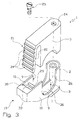
- Number 1 in Figures 1 to 3 indicates a cable clamping device comprising a base 2 having a seat 3, through which are housed one or more electric cables, e.g. a bundle of cables 4a, 4b, 4c for supplying an electric household appliance (not shown) and differing widely in size - in the example shown, in diameter.
- Cable clamping device 1 also comprises a clamping member 5, which is insertable inside base 2, crosswise to seat 3, through a mouth 6 formed in base 2 and directly facing the seat 3, to clamp cables 4 against a bottom wall 7 of seat 2.
- Clamping member 5 and base 2 are defined, in the example shown, by respective cup-shaped, substantially parallelepiped-shaped bodies molded from synthetic plastic, preferably thermoplastic, material and insertable the first inside the second.
- the through seat 3 for cables 4 includes part of an inner cavity 8 of the cup-shaped body defining base 2; and two facing U-shaped openings 9 formed through respective peripheral lateral walls 10 of base 2, with their respective concavities facing mouth 6 of base 2, defined on the open side of the cup-shaped body defining base 2.
- Clamping member 5 and base 2 are preferably connected integrally to each other by a deformable tongue 11 - shown by the dash line in Figure 1 - so they can be molded in known manner in one operation, with the respective concavities facing the same way, and then positioned, in use, with the concavities facing, as shown in the drawings.
- base 2 comprises known click-on retaining means 12 for connection to a support 13, e.g. the casing of an electric household appliance, and may be formed as a separate part, or integrally with a body 14 of a known terminal board (not shown for the sake of simplicity), so that device 1 is integrated in the known terminal board.
- device 1 also comprises a jack device 18, by which clamping member 5 is secured adjustably to base 2, at least partly inside seat 3.
- Jack device 18 is formed at the end 19 of cable clamping device 1 opposite tongue 11, and comprises an L-shaped rib 20 formed in one piece with clamping member 5 and having transverse teeth 21; and a recess 22 formed in base 2, alongside seat 3, to longitudinally accommodate the whole length of rib 20, and having, internally, at least one elastically deformable tooth 23 located so as to click, in use, onto teeth 21.
- Clamping member 5 also comprises, on the opposite side to rib 20, at least one hole 24 for receiving a respective screw 25 (shown only partly in Figure 3) or other similar removable fastening member; and base 2 comprises, on the opposite side to recess 22, at least one fastening seat 26 for receiving screw 25, and which is defined, in the example shown, by a tubular stem projecting inside cavity 8, between walls 10 and on one side of openings 9, which are therefore interposed between fastening seat 26 and recess 22.
- Recess 22 is separated from seat 3 by a wall 29 parallel to seat 3, and is therefore defined by the part of cavity 8 separated by wall 29 from the part of the cavity defining seat 3. Tooth 23 is formed in one piece with base 2 at end 19 and at a mouth 30 of recess 22 aligned with mouth 6 of seat 2.
- Tooth 23 projects inside recess 22, on the opposite side to and parallel to wall 29, and is defined, towards wall 29, by a sloping surface 33, which extends partly inside mouth 30 so as to at least partly occupy mouth 30 when viewed from above ( Figure 2).
- Rib 20 projects laterally from clamping member 5 in such a position ( Figures 1 and 3) as to rest, in use, on and astride wall 29, and to interfere with tooth 23 - in particular, by teeth 21 interfering with sloping surface 33 - when clamping member 5 is inserted in the direction of arrow A inside base 2; for which purpose, teeth 21 are formed on the face of rib 20 facing tooth 23 in use.
- Teeth 21 are serrated, and comprise a number of triangular teeth defined by respective sloping surfaces 34, which, in use, when rib 20 is positioned parallel to wall 29, are oriented parallel to and facing sloping surface 33.
- member 5 has a contact edge 35, which, in the example shown, is semicircular, but which may be any shape, e.g. wedge-shaped.
- member 5 is arrested, and tooth 23 engaging teeth 21 holds member 5 in position, and maintains pressure on, and so ensures firm clamping of, cables 4.
- member 5 is also retained the normal way by means of one or more screws 25.
- screw 25 if provided, is first removed, and a tool, e.g. a screwdriver 38 illustrated by the fine line in Figure 1, is inserted inside mouth 30 in the sloping direction indicated by arrow C, is pressed against sloping surface 33, and is rotated in the direction of arrow R to flex tooth 23 and so release teeth 21.
- a tool e.g. a screwdriver 38 illustrated by the fine line in Figure 1
- rib 20 can therefore also be withdrawn from recess 22.
Landscapes
- Installation Of Indoor Wiring (AREA)
- Insertion, Bundling And Securing Of Wires For Electric Apparatuses (AREA)
Applications Claiming Priority (2)
| Application Number | Priority Date | Filing Date | Title |
|---|---|---|---|
| ITMI20010941 | 2001-05-08 | ||
| IT2001MI000941A ITMI20010941A1 (it) | 2001-05-08 | 2001-05-08 | Dispositivo serracavo particolarmente adatto al bloccaggio di fasci di cavi |
Publications (2)
| Publication Number | Publication Date |
|---|---|
| EP1257011A2 true EP1257011A2 (fr) | 2002-11-13 |
| EP1257011A3 EP1257011A3 (fr) | 2003-09-24 |
Family
ID=11447612
Family Applications (1)
| Application Number | Title | Priority Date | Filing Date |
|---|---|---|---|
| EP02010371A Withdrawn EP1257011A3 (fr) | 2001-05-08 | 2002-05-07 | Dispositif de serrage de câble, en particulier pour maintenir un faisceau de câbles |
Country Status (2)
| Country | Link |
|---|---|
| EP (1) | EP1257011A3 (fr) |
| IT (1) | ITMI20010941A1 (fr) |
Cited By (10)
| Publication number | Priority date | Publication date | Assignee | Title |
|---|---|---|---|---|
| WO2006066231A1 (fr) * | 2004-12-17 | 2006-06-22 | Panduit Corp. | Bouchon de protection de cable avec clip de serrage integral |
| EP1798821A3 (fr) * | 2005-12-15 | 2007-10-03 | Necto Group S.r.l. | Boîtier de raccordement pour connections électriques |
| WO2008004094A3 (fr) * | 2006-07-06 | 2008-05-08 | Itw Ind Components Srl | Dispositif serre-câbles |
| EP1848067A3 (fr) * | 2006-04-21 | 2010-07-14 | REHAU AG + Co | Dispositif de fixation pour câble |
| US8968024B2 (en) | 2012-01-24 | 2015-03-03 | Panduit Corp. | Communication connector with wire containment cap for improved cable retention |
| CN113376637A (zh) * | 2021-06-30 | 2021-09-10 | 海南电网有限责任公司白沙供电局 | 一种电网线路树障测量装置 |
| TWI759201B (zh) * | 2021-02-26 | 2022-03-21 | 大陸商立訊精密工業股份有限公司 | 一種線纜固定夾具及數據傳輸裝置 |
| CN114583644A (zh) * | 2022-03-03 | 2022-06-03 | 段旭 | 一种电缆夹持装置及其使用方法 |
| JP2023183820A (ja) * | 2022-06-16 | 2023-12-28 | 矢崎総業株式会社 | 部品結合構造及びワイヤハーネス |
| US12048991B2 (en) | 2020-10-20 | 2024-07-30 | Hyster-Yale Group, Inc. | Clamp for elongate objects |
Family Cites Families (6)
| Publication number | Priority date | Publication date | Assignee | Title |
|---|---|---|---|---|
| NL168664C (nl) * | 1973-02-16 | 1982-04-16 | Draka Kabel Bv | Kabelmof. |
| US4516822A (en) * | 1984-02-27 | 1985-05-14 | Amp Incorporated | Round cable adaptor for modular plug |
| GB2183405B (en) * | 1985-11-25 | 1989-10-04 | Plastic Seals Limited | Improvements in or relating to clamping devices for electrical conductors and the like |
| GB8612588D0 (en) * | 1986-05-23 | 1986-07-02 | Kinloch Electronics Ltd | Cable clamp |
| DE9303368U1 (de) * | 1993-03-08 | 1993-05-27 | Electro-Terminal Gesellschaft m.b.H., Innsbruck | Zugentlastungsvorrichtung |
| US5653609A (en) * | 1995-07-28 | 1997-08-05 | The Whitaker Corporation | Strain relief for an electrical connector |
-
2001
- 2001-05-08 IT IT2001MI000941A patent/ITMI20010941A1/it unknown
-
2002
- 2002-05-07 EP EP02010371A patent/EP1257011A3/fr not_active Withdrawn
Cited By (21)
| Publication number | Priority date | Publication date | Assignee | Title |
|---|---|---|---|---|
| WO2006066231A1 (fr) * | 2004-12-17 | 2006-06-22 | Panduit Corp. | Bouchon de protection de cable avec clip de serrage integral |
| US8298000B2 (en) | 2004-12-17 | 2012-10-30 | Panduit Corp. | Wire containment cap with an integral strain relief clip |
| US8109784B2 (en) | 2004-12-17 | 2012-02-07 | Panduit Corp. | Wire containment cap with an integral strain relief clip |
| CN101080856B (zh) * | 2004-12-17 | 2011-01-19 | 泛达公司 | 具有组合式应变减除夹头的导线护罩 |
| US7476120B2 (en) | 2004-12-17 | 2009-01-13 | Panduit Corp. | Wire containment cap with an integral strain relief clip |
| CN1983722B (zh) * | 2005-12-15 | 2010-06-16 | 奈克托集团有限公司 | 用于电连接的接线盒 |
| US7467966B2 (en) | 2005-12-15 | 2008-12-23 | Necto Group S.R.L. | Terminal box for electrical connections |
| EP1798821A3 (fr) * | 2005-12-15 | 2007-10-03 | Necto Group S.r.l. | Boîtier de raccordement pour connections électriques |
| EP1848067A3 (fr) * | 2006-04-21 | 2010-07-14 | REHAU AG + Co | Dispositif de fixation pour câble |
| US8030573B2 (en) | 2006-07-06 | 2011-10-04 | Itw Industrial Components S.R.L. Con Unico Socio | Cable-clamping device |
| WO2008004094A3 (fr) * | 2006-07-06 | 2008-05-08 | Itw Ind Components Srl | Dispositif serre-câbles |
| US9337572B2 (en) | 2012-01-24 | 2016-05-10 | Panduit Corp. | Communication connector with wire containment cap for improved cable retention |
| US8968024B2 (en) | 2012-01-24 | 2015-03-03 | Panduit Corp. | Communication connector with wire containment cap for improved cable retention |
| US12048991B2 (en) | 2020-10-20 | 2024-07-30 | Hyster-Yale Group, Inc. | Clamp for elongate objects |
| TWI759201B (zh) * | 2021-02-26 | 2022-03-21 | 大陸商立訊精密工業股份有限公司 | 一種線纜固定夾具及數據傳輸裝置 |
| US11509091B2 (en) | 2021-02-26 | 2022-11-22 | Luxshare Precision Industry Co., Ltd. | Cable securing clamp and data transmission device |
| CN113376637A (zh) * | 2021-06-30 | 2021-09-10 | 海南电网有限责任公司白沙供电局 | 一种电网线路树障测量装置 |
| CN113376637B (zh) * | 2021-06-30 | 2023-01-06 | 海南电网有限责任公司白沙供电局 | 一种电网线路树障测量装置 |
| CN114583644A (zh) * | 2022-03-03 | 2022-06-03 | 段旭 | 一种电缆夹持装置及其使用方法 |
| CN114583644B (zh) * | 2022-03-03 | 2023-09-29 | 国网黑龙江省电力有限公司伊春供电公司 | 一种电缆夹持装置及其使用方法 |
| JP2023183820A (ja) * | 2022-06-16 | 2023-12-28 | 矢崎総業株式会社 | 部品結合構造及びワイヤハーネス |
Also Published As
| Publication number | Publication date |
|---|---|
| ITMI20010941A1 (it) | 2002-11-08 |
| EP1257011A3 (fr) | 2003-09-24 |
| ITMI20010941A0 (it) | 2001-05-08 |
Similar Documents
| Publication | Publication Date | Title |
|---|---|---|
| EP1257011A2 (fr) | Dispositif de serrage de câble, en particulier pour maintenir un faisceau de câbles | |
| US3976348A (en) | Electrical tab receptacle | |
| US8556649B2 (en) | Fixing device for fixing a cable at a housing feed-through | |
| CN100382391C (zh) | 电缆接头 | |
| KR101076340B1 (ko) | 수형 부분과 암형 부분을 포함하는, 2개의 경질 튜브형물체를 연결하기 위한 장치 | |
| JP5289301B2 (ja) | 電気的接続器具のロック用カバー | |
| US20030207606A1 (en) | Locking and releasable electrical receptacle/connector | |
| CN103531921A (zh) | 触点线夹和具有触点线夹的连接器 | |
| KR20080077908A (ko) | 전기적 접속기구의 로크구조 | |
| JP4511521B2 (ja) | 壁貫通端子形プラグコネクター | |
| JP7689591B2 (ja) | ケーブルコネクタユニット用挟持要素及び当該挟持要素を備えたケーブルコネクタユニット | |
| MXPA02002727A (es) | Dispositivo de retencion axial de un elemento cilindrico y mas particularmente un cable. | |
| FI108483B (fi) | Sõhk÷pistorasia, jolla on parannetut irtikytkentõominaisuudet | |
| US6479754B1 (en) | Strain relief system for electrical cable | |
| AU2004219446A1 (en) | Plug adapter | |
| US7367842B2 (en) | Coaxial connecting plug | |
| CN116670943A (zh) | 插头组件 | |
| EP0429136A1 (fr) | Assemblage de connecteur | |
| KR101687109B1 (ko) | 전선관용 접속장치 | |
| JP2025056792A (ja) | 端子ハウジング | |
| EP1208617A1 (fr) | Prise electrique | |
| HU203619B (en) | Electric connecting terminal with clamping screw braked opposed to unscrewing | |
| CN211958032U (zh) | 一种方便安装电线的插座 | |
| JP2016144288A (ja) | オプションコネクタ用固定具 | |
| CN117413438A (zh) | 绞线保护板 |
Legal Events
| Date | Code | Title | Description |
|---|---|---|---|
| PUAI | Public reference made under article 153(3) epc to a published international application that has entered the european phase |
Free format text: ORIGINAL CODE: 0009012 |
|
| AK | Designated contracting states |
Kind code of ref document: A2 Designated state(s): AT BE CH CY DE DK ES FI FR GB GR IE IT LI LU MC NL PT SE TR |
|
| AX | Request for extension of the european patent |
Free format text: AL;LT;LV;MK;RO;SI |
|
| PUAL | Search report despatched |
Free format text: ORIGINAL CODE: 0009013 |
|
| AK | Designated contracting states |
Kind code of ref document: A3 Designated state(s): AT BE CH CY DE DK ES FI FR GB GR IE IT LI LU MC NL PT SE TR |
|
| AX | Request for extension of the european patent |
Extension state: AL LT LV MK RO SI |
|
| AKX | Designation fees paid | ||
| REG | Reference to a national code |
Ref country code: DE Ref legal event code: 8566 |
|
| STAA | Information on the status of an ep patent application or granted ep patent |
Free format text: STATUS: THE APPLICATION IS DEEMED TO BE WITHDRAWN |
|
| 18D | Application deemed to be withdrawn |
Effective date: 20040325 |