EP1258043B1 - Dispositif et procede pour l'equilibrage de temperature d'un corps multicouche - Google Patents
Dispositif et procede pour l'equilibrage de temperature d'un corps multicouche Download PDFInfo
- Publication number
- EP1258043B1 EP1258043B1 EP00962177.2A EP00962177A EP1258043B1 EP 1258043 B1 EP1258043 B1 EP 1258043B1 EP 00962177 A EP00962177 A EP 00962177A EP 1258043 B1 EP1258043 B1 EP 1258043B1
- Authority
- EP
- European Patent Office
- Prior art keywords
- layer
- energy
- container
- tempering
- energy source
- Prior art date
- Legal status (The legal status is an assumption and is not a legal conclusion. Google has not performed a legal analysis and makes no representation as to the accuracy of the status listed.)
- Expired - Lifetime
Links
- 238000000034 method Methods 0.000 title claims description 161
- 238000000137 annealing Methods 0.000 title 1
- 230000008569 process Effects 0.000 claims description 135
- 238000005496 tempering Methods 0.000 claims description 89
- 230000005855 radiation Effects 0.000 claims description 57
- 230000005670 electromagnetic radiation Effects 0.000 claims description 37
- 239000000463 material Substances 0.000 claims description 32
- 230000008878 coupling Effects 0.000 claims description 27
- 238000010168 coupling process Methods 0.000 claims description 27
- 238000005859 coupling reaction Methods 0.000 claims description 27
- 239000011521 glass Substances 0.000 claims description 25
- 238000010521 absorption reaction Methods 0.000 claims description 18
- 125000006850 spacer group Chemical group 0.000 claims description 15
- 238000010924 continuous production Methods 0.000 claims description 12
- BUGBHKTXTAQXES-UHFFFAOYSA-N Selenium Chemical compound [Se] BUGBHKTXTAQXES-UHFFFAOYSA-N 0.000 claims description 11
- 239000002241 glass-ceramic Substances 0.000 claims description 11
- 239000011669 selenium Substances 0.000 claims description 10
- 229910052711 selenium Inorganic materials 0.000 claims description 9
- 239000000126 substance Substances 0.000 claims description 8
- RYGMFSIKBFXOCR-UHFFFAOYSA-N Copper Chemical compound [Cu] RYGMFSIKBFXOCR-UHFFFAOYSA-N 0.000 claims description 6
- GYHNNYVSQQEPJS-UHFFFAOYSA-N Gallium Chemical compound [Ga] GYHNNYVSQQEPJS-UHFFFAOYSA-N 0.000 claims description 6
- 230000033228 biological regulation Effects 0.000 claims description 6
- 229910052802 copper Inorganic materials 0.000 claims description 6
- 239000010949 copper Substances 0.000 claims description 6
- 230000001419 dependent effect Effects 0.000 claims description 6
- 238000001514 detection method Methods 0.000 claims description 6
- 229910052733 gallium Inorganic materials 0.000 claims description 6
- 229910052738 indium Inorganic materials 0.000 claims description 5
- APFVFJFRJDLVQX-UHFFFAOYSA-N indium atom Chemical compound [In] APFVFJFRJDLVQX-UHFFFAOYSA-N 0.000 claims description 5
- 229910052751 metal Inorganic materials 0.000 claims description 5
- 239000002184 metal Substances 0.000 claims description 5
- 239000004033 plastic Substances 0.000 claims description 5
- 229910052717 sulfur Inorganic materials 0.000 claims description 5
- NINIDFKCEFEMDL-UHFFFAOYSA-N Sulfur Chemical compound [S] NINIDFKCEFEMDL-UHFFFAOYSA-N 0.000 claims description 4
- 238000009826 distribution Methods 0.000 claims description 4
- 239000011593 sulfur Substances 0.000 claims description 4
- 239000000919 ceramic Substances 0.000 claims description 3
- 230000000284 resting effect Effects 0.000 claims description 3
- 238000009434 installation Methods 0.000 claims 1
- 239000010410 layer Substances 0.000 description 231
- 239000007789 gas Substances 0.000 description 99
- 238000010438 heat treatment Methods 0.000 description 21
- OKTJSMMVPCPJKN-UHFFFAOYSA-N Carbon Chemical compound [C] OKTJSMMVPCPJKN-UHFFFAOYSA-N 0.000 description 12
- 229910002804 graphite Inorganic materials 0.000 description 11
- 239000010439 graphite Substances 0.000 description 11
- 239000010409 thin film Substances 0.000 description 10
- 229910052736 halogen Inorganic materials 0.000 description 9
- 150000002367 halogens Chemical class 0.000 description 9
- ZOKXTWBITQBERF-UHFFFAOYSA-N Molybdenum Chemical compound [Mo] ZOKXTWBITQBERF-UHFFFAOYSA-N 0.000 description 8
- 230000005540 biological transmission Effects 0.000 description 8
- 229910052750 molybdenum Inorganic materials 0.000 description 8
- 239000011733 molybdenum Substances 0.000 description 8
- 239000004065 semiconductor Substances 0.000 description 7
- 230000008901 benefit Effects 0.000 description 6
- 238000001816 cooling Methods 0.000 description 6
- 239000011159 matrix material Substances 0.000 description 6
- 239000000758 substrate Substances 0.000 description 6
- 230000003595 spectral effect Effects 0.000 description 5
- 230000001052 transient effect Effects 0.000 description 5
- KTSFMFGEAAANTF-UHFFFAOYSA-N [Cu].[Se].[Se].[In] Chemical compound [Cu].[Se].[Se].[In] KTSFMFGEAAANTF-UHFFFAOYSA-N 0.000 description 4
- 238000005452 bending Methods 0.000 description 4
- 239000011248 coating agent Substances 0.000 description 4
- 238000000576 coating method Methods 0.000 description 4
- 239000002346 layers by function Substances 0.000 description 4
- 239000005361 soda-lime glass Substances 0.000 description 4
- VYPSYNLAJGMNEJ-UHFFFAOYSA-N Silicium dioxide Chemical compound O=[Si]=O VYPSYNLAJGMNEJ-UHFFFAOYSA-N 0.000 description 3
- 238000003491 array Methods 0.000 description 3
- 230000001276 controlling effect Effects 0.000 description 3
- 239000011888 foil Substances 0.000 description 3
- 229910052739 hydrogen Inorganic materials 0.000 description 3
- 239000011261 inert gas Substances 0.000 description 3
- 238000004556 laser interferometry Methods 0.000 description 3
- 230000002123 temporal effect Effects 0.000 description 3
- 229920000049 Carbon (fiber) Polymers 0.000 description 2
- 239000004917 carbon fiber Substances 0.000 description 2
- 230000008859 change Effects 0.000 description 2
- 239000001257 hydrogen Substances 0.000 description 2
- 238000005259 measurement Methods 0.000 description 2
- VNWKTOKETHGBQD-UHFFFAOYSA-N methane Chemical compound C VNWKTOKETHGBQD-UHFFFAOYSA-N 0.000 description 2
- 239000000203 mixture Substances 0.000 description 2
- 230000003287 optical effect Effects 0.000 description 2
- 230000035699 permeability Effects 0.000 description 2
- 230000035939 shock Effects 0.000 description 2
- IJGRMHOSHXDMSA-UHFFFAOYSA-N Atomic nitrogen Chemical compound N#N IJGRMHOSHXDMSA-UHFFFAOYSA-N 0.000 description 1
- 208000031872 Body Remains Diseases 0.000 description 1
- ZAMOUSCENKQFHK-UHFFFAOYSA-N Chlorine atom Chemical compound [Cl] ZAMOUSCENKQFHK-UHFFFAOYSA-N 0.000 description 1
- RWSOTUBLDIXVET-UHFFFAOYSA-N Dihydrogen sulfide Chemical compound S RWSOTUBLDIXVET-UHFFFAOYSA-N 0.000 description 1
- UFHFLCQGNIYNRP-UHFFFAOYSA-N Hydrogen Chemical compound [H][H] UFHFLCQGNIYNRP-UHFFFAOYSA-N 0.000 description 1
- BKQMNPVDJIHLPD-UHFFFAOYSA-N OS(=O)(=O)[Se]S(O)(=O)=O Chemical compound OS(=O)(=O)[Se]S(O)(=O)=O BKQMNPVDJIHLPD-UHFFFAOYSA-N 0.000 description 1
- 239000004809 Teflon Substances 0.000 description 1
- 229920006362 Teflon® Polymers 0.000 description 1
- 230000002745 absorbent Effects 0.000 description 1
- 239000002250 absorbent Substances 0.000 description 1
- 230000009471 action Effects 0.000 description 1
- 239000000956 alloy Substances 0.000 description 1
- 229910045601 alloy Inorganic materials 0.000 description 1
- QVGXLLKOCUKJST-UHFFFAOYSA-N atomic oxygen Chemical compound [O] QVGXLLKOCUKJST-UHFFFAOYSA-N 0.000 description 1
- 229910052799 carbon Inorganic materials 0.000 description 1
- 238000006243 chemical reaction Methods 0.000 description 1
- 229910052801 chlorine Inorganic materials 0.000 description 1
- 239000000460 chlorine Substances 0.000 description 1
- HVMJUDPAXRRVQO-UHFFFAOYSA-N copper indium Chemical compound [Cu].[In] HVMJUDPAXRRVQO-UHFFFAOYSA-N 0.000 description 1
- 230000007797 corrosion Effects 0.000 description 1
- 238000005260 corrosion Methods 0.000 description 1
- 230000003247 decreasing effect Effects 0.000 description 1
- 238000000151 deposition Methods 0.000 description 1
- 230000000694 effects Effects 0.000 description 1
- 230000005281 excited state Effects 0.000 description 1
- 239000000835 fiber Substances 0.000 description 1
- 239000001307 helium Substances 0.000 description 1
- 229910052734 helium Inorganic materials 0.000 description 1
- SWQJXJOGLNCZEY-UHFFFAOYSA-N helium atom Chemical compound [He] SWQJXJOGLNCZEY-UHFFFAOYSA-N 0.000 description 1
- 238000000265 homogenisation Methods 0.000 description 1
- 150000004678 hydrides Chemical class 0.000 description 1
- 150000002431 hydrogen Chemical class 0.000 description 1
- 229910000037 hydrogen sulfide Inorganic materials 0.000 description 1
- 238000004519 manufacturing process Methods 0.000 description 1
- 238000003032 molecular docking Methods 0.000 description 1
- 230000001590 oxidative effect Effects 0.000 description 1
- 229910052760 oxygen Inorganic materials 0.000 description 1
- 239000001301 oxygen Substances 0.000 description 1
- 231100000614 poison Toxicity 0.000 description 1
- 230000007096 poisonous effect Effects 0.000 description 1
- 238000010926 purge Methods 0.000 description 1
- 230000001105 regulatory effect Effects 0.000 description 1
- 229910000058 selane Inorganic materials 0.000 description 1
- 239000002356 single layer Substances 0.000 description 1
- 239000002689 soil Substances 0.000 description 1
- 230000006641 stabilisation Effects 0.000 description 1
- 238000011105 stabilization Methods 0.000 description 1
- 231100000331 toxic Toxicity 0.000 description 1
- 230000002588 toxic effect Effects 0.000 description 1
- 230000007723 transport mechanism Effects 0.000 description 1
Images



Classifications
-
- H—ELECTRICITY
- H10—SEMICONDUCTOR DEVICES; ELECTRIC SOLID-STATE DEVICES NOT OTHERWISE PROVIDED FOR
- H10F—INORGANIC SEMICONDUCTOR DEVICES SENSITIVE TO INFRARED RADIATION, LIGHT, ELECTROMAGNETIC RADIATION OF SHORTER WAVELENGTH OR CORPUSCULAR RADIATION
- H10F77/00—Constructional details of devices covered by this subclass
- H10F77/10—Semiconductor bodies
- H10F77/12—Active materials
-
- B—PERFORMING OPERATIONS; TRANSPORTING
- B32—LAYERED PRODUCTS
- B32B—LAYERED PRODUCTS, i.e. PRODUCTS BUILT-UP OF STRATA OF FLAT OR NON-FLAT, e.g. CELLULAR OR HONEYCOMB, FORM
- B32B38/00—Ancillary operations in connection with laminating processes
- B32B38/0036—Heat treatment
-
- H—ELECTRICITY
- H10—SEMICONDUCTOR DEVICES; ELECTRIC SOLID-STATE DEVICES NOT OTHERWISE PROVIDED FOR
- H10F—INORGANIC SEMICONDUCTOR DEVICES SENSITIVE TO INFRARED RADIATION, LIGHT, ELECTROMAGNETIC RADIATION OF SHORTER WAVELENGTH OR CORPUSCULAR RADIATION
- H10F10/00—Individual photovoltaic cells, e.g. solar cells
- H10F10/10—Individual photovoltaic cells, e.g. solar cells having potential barriers
- H10F10/16—Photovoltaic cells having only PN heterojunction potential barriers
- H10F10/167—Photovoltaic cells having only PN heterojunction potential barriers comprising Group I-III-VI materials, e.g. CdS/CuInSe2 [CIS] heterojunction photovoltaic cells
-
- H—ELECTRICITY
- H10—SEMICONDUCTOR DEVICES; ELECTRIC SOLID-STATE DEVICES NOT OTHERWISE PROVIDED FOR
- H10F—INORGANIC SEMICONDUCTOR DEVICES SENSITIVE TO INFRARED RADIATION, LIGHT, ELECTROMAGNETIC RADIATION OF SHORTER WAVELENGTH OR CORPUSCULAR RADIATION
- H10F71/00—Manufacture or treatment of devices covered by this subclass
-
- B—PERFORMING OPERATIONS; TRANSPORTING
- B32—LAYERED PRODUCTS
- B32B—LAYERED PRODUCTS, i.e. PRODUCTS BUILT-UP OF STRATA OF FLAT OR NON-FLAT, e.g. CELLULAR OR HONEYCOMB, FORM
- B32B2310/00—Treatment by energy or chemical effects
- B32B2310/08—Treatment by energy or chemical effects by wave energy or particle radiation
- B32B2310/0806—Treatment by energy or chemical effects by wave energy or particle radiation using electromagnetic radiation
-
- Y—GENERAL TAGGING OF NEW TECHNOLOGICAL DEVELOPMENTS; GENERAL TAGGING OF CROSS-SECTIONAL TECHNOLOGIES SPANNING OVER SEVERAL SECTIONS OF THE IPC; TECHNICAL SUBJECTS COVERED BY FORMER USPC CROSS-REFERENCE ART COLLECTIONS [XRACs] AND DIGESTS
- Y02—TECHNOLOGIES OR APPLICATIONS FOR MITIGATION OR ADAPTATION AGAINST CLIMATE CHANGE
- Y02E—REDUCTION OF GREENHOUSE GAS [GHG] EMISSIONS, RELATED TO ENERGY GENERATION, TRANSMISSION OR DISTRIBUTION
- Y02E10/00—Energy generation through renewable energy sources
- Y02E10/50—Photovoltaic [PV] energy
- Y02E10/541—CuInSe2 material PV cells
Definitions
- the invention relates to a device for tempering a multi-layer body having a first and at least a second layer by receiving an amount of energy through the multi-layer body with a recording of a first subset of the amount of energy through the first layer and a recording of a second subset of the amount of energy through the second Layer comprising at least one energy source.
- a device for example off EP 0 662 247 B1 known.
- a method for tempering a multilayer body and such a multilayer body are presented.
- US 5861609 A1 and EP 0399662 A2 show a device in which a coated substrate between two graphite plates is placed in a quartz glass tube for heat treatment.
- a multilayer body is produced, for example, by applying a functional layer to a carrier layer (substrate).
- a functional layer to have a desired physical (electrical, mechanical, etc.) and / or chemical property
- the processing includes, for example, a tempering of the multilayer body in the presence of a gas (process gas).
- a multi-layer body is, for example, a thin-film solar cell in which an electrode layer of molybdenum and a functional copper indium diselenide (CIS) semiconductor layer are applied to a carrier layer of glass.
- This thin film solar cell is according to EP 0 662 247 B1 made in a two-step process. In a first stage, the following elements are applied in layer form to the glass support layer in sequence: molybdenum, copper, indium and selenium.
- the multilayer body thus obtained is in a second Tempered stage, forming the copper-indium-diselenide - semiconductor layer.
- the multilayer body is arranged in a closed container made of graphite.
- a certain partial pressure of gaseous selenium is formed in the interior of the container, with the layers applied to the glass being in contact with the gaseous selenium.
- the multi-layer body absorbs an amount of energy, wherein each layer is supplied a subset of the amount of energy.
- the tempering takes place, for example, with a heating rate of 10 ° C / s.
- a halogen lamp is used as the energy source of the amount of energy.
- the container is irradiated graphite and thus heated the container.
- graphite as a quasi "blackbody”
- the amount of energy absorbed by the graphite is supplied to the multilayer body by thermal radiation and / or heat conduction.
- the container thus acts as a secondary energy source or as an energy transmitter.
- Graphite has a high emissivity and high thermal conductivity.
- the supply of the amount of energy on an underside of the multilayer body takes place essentially by heat conduction.
- An upper side of the multilayer body is supplied with an amount of energy by thermal radiation.
- Due to an asymmetrical layer structure of the multilayer body and / or a different supply of the amount of energy to the top and bottom of the multilayer body can at a high heating rate to an inhomogeneous, ie non-uniform tempering of the layers of the multilayer body come. It may form a temperature inhomogeneity in the thickness direction of the multilayer body, which may result in a temperature expansion coefficient of a material of a layer, which is different from zero, within the layer and / or the multilayer body to a mechanical stress. This mechanical stress can detect a crack or breakage of the layer and / or the multilayer body. The mechanical stress can also lead to a deformation (warp) of the multilayer body.
- the deformation is generally transient in the case of a carrier layer made of glass, ie after the temperature control, the deformation is formed back.
- the deformation can also be permanent. The deformation does not reform. This is the case when a softening point of the carrier layer (for example made of glass) is exceeded during tempering and thereby an (internal) mechanical stress and / or an external force becomes effective.
- tempering rate heating rate, cooling rate
- the object of the invention is to show how a temperature homogeneity or temperature inhomogeneity can be influenced in a targeted manner during the tempering of a large-area multilayer body with a high tempering rate.
- a device for tempering a multilayer body according to claim 1 is given.
- the idea of the invention is to heat the layers of the multilayer body individually, ie to selectively control, regulate and / or preset the subset of the amount of energy that a layer takes up. For example, an amount of energy is determined by means of a control loop during tempering (see below). It is also conceivable that a presetting of the energy sources (eg energy density, type of energy, etc.) is sufficient without an additional control loop.
- an individual heating of the layers of the multilayer body is possible even at very high heating rates of 1 ° C / s to, for example, 50 ° C / s and more. Due to the individual heating, it is possible during the tempering to keep a mechanical stress and a possible deformation of the multilayer body possibly occurring as small as possible.
- the transparency body which is semi-transparent (semitransparent).
- the electromagnetic radiation described above passes through the transparency body on a layer.
- the layer can receive a corresponding amount of energy or subset of the amount of energy that is emitted directly from the energy source.
- the transparency also has some absorption for the electromagnetic radiation.
- the energy absorbed with it can be released in the form of heat radiation and / or heat conduction to an environment.
- the device for tempering a multilayer body has a transparent body, which has a heat radiation and / or heat conduction in the direction of the multilayer body due to the absorption of the electromagnetic radiation.
- a first layer of the multilayer body which exhibits a transmission for the heat radiation, is tempered substantially only by heat conduction, while a second layer of the same multilayer body is substantially tempered by the heat radiation of the same transparency body.
- a first layer with a corresponding transmission is, for example, a layer of glass.
- an electromagnetic radiation of an energy source and / or a transparent body hits the glass body, a small proportion of the radiation (about 4%) is reflected. The largest proportion (> 90%) passes through the glass more or less unhindered and then strikes a second layer of the multilayer body. There, this radiation can be absorbed and lead to a recording of an amount of energy through this second layer.
- the glass layer can not be heated sufficiently quickly by radiation or heat radiation at a very high heating rate. In contrast, a relatively rapid tempering by conduction is possible, if the transparency body can absorb a subset of the amount of energy and transfer it to the glass layer.
- the transparency itself is a layer of the multilayer body.
- the transparency body can absorb a subset of the amount of energy and transmit through the transmission a further subset of the amount of energy for absorption by another layer.
- a multilayer body is used in the method in which a layer acts as a carrier layer for at least one further layer.
- the multilayer body has in particular an asymmetrical layer sequence.
- the multilayer body consists of a carrier layer coated on one side. Individual layers of the multilayer body can also be arranged next to one another.
- a layer of the multilayer body to a material which is selected from the group glass, glass ceramic, ceramic, metal and / or plastic.
- a material which is selected from the group glass, glass ceramic, ceramic, metal and / or plastic.
- temperature-resistant plastic such as Teflon is suitable as the plastic.
- a layer is, for example, a metal foil.
- the metal foil can also function as a carrier layer.
- the subset of the amount of energy absorbed by a layer depends, for example, on an absorption, emission and / or reflection property of the layer. However, it also depends on the type of energy source and on the way in which the amount of energy is transferred to the multilayer body or to a layer of the multilayer body.
- the tempering of the multilayer body or of a layer takes place, for example, with the aid of a source of energy for thermal energy.
- the layer the thermal energy be fed directly.
- heat radiation heat conduction and / or convection in question.
- the energy source itself may be a source of thermal radiation.
- the heat radiation is, for example, electromagnetic radiation in the wavelength range between 0.7 and 4.5 ⁇ m (infrared light).
- the corresponding layer is arranged in the radiation field of the energy source. The layer is struck by the electromagnetic radiation of the energy source and at least partially absorbs the electromagnetic radiation.
- a layer of any energy is supplied, which is converted into thermal energy in the layer.
- a layer is irradiated with high-energy UV light, which absorbs the layer.
- high-energy light quantum By absorbing a high-energy light quantum, a molecule of the layer or the entire layer enters an electronically excited state. A recorded energy can be converted into thermal energy.
- a layer can also be cooled.
- the layer is fed to a negative thermal energy.
- an energy transmitter for transmitting the amount of energy to the multi-layer body available.
- the energy transmitter acts as a secondary energy source.
- the energy transmitter absorbs electromagnetic radiation from a primary energy source, such as a halogen lamp, from a higher energy range and converts that electromagnetic radiation into thermal radiation that is absorbed by the layer.
- the indirect and / or immediate environment of the multilayer body can act during the tempering. It is conceivable that an energy transmitter is arranged with the multilayer body for tempering in an interior of a container.
- the energy transmitter can also be arranged outside the container, for example on a wall of the container or at a distance from the container. It is conceivable that the energy transmitter is a coating of the container.
- the energy transmitter is, for example, a graphite foil.
- the container itself can also take over the function of an energy transmitter. Such a function is given for example in a container made of graphite.
- the transparency is nothing more than an energy transmitter.
- a gas acts as an energy transmitter in an energy transfer by convection.
- An amount of energy taken up by the multilayer body may vary not only from layer to layer but also within a layer.
- a tempering effect occurs in the multilayer body or in a layer of a multilayer body during tempering.
- An edge region of the layer has a different temperature than an inner region of the layer. It turns during tempering a lateral temperature gradient. This happens, for example, when a radiation field of the energy source is inhomogeneous. In this case, an energy density of the radiation field on a surface which is irradiated by the radiation is not the same everywhere.
- a lateral temperature inhomogeneity can also occur with a homogeneous radiation field, if at the edge of a layer due to the larger absorbing area per unit volume of a larger amount of energy per unit volume is absorbed.
- an energy source consisting of a plurality of subunits can be used. Each subunit can be driven separately, thus separately adjusting each amount of energy supplied by a subunit to a layer.
- Such an energy source is for example an array or a matrix of individual heating elements.
- a heating element is for example a halogen lamp.
- the array or matrix may also be used to establish a lateral temperature gradient in the layer. As a result, one could, for example, selectively generate a permanent or transient deformation of the layered body.
- an array or matrix is of great advantage
- the energy source it is advantageous if the energy source or the energy sources operate in a continuous operation. It is also conceivable that the energy sources in a cycle and / or pulsed operation provide the amount of energy or the subsets of the amount of energy available to the layers.
- Such an energy source is, for example, an energy source with pulsed electromagnetic radiation. In this way, an amount of energy may be supplied to the layers at the same time or in a temporal sequence (e.g., alternating).
- the transparent body of the device has at least one spacer to which the multi-layer body can be applied by the multi-layer body for receiving a laterally homogeneous amount of energy.
- the layer over which the multilayer body rests on the transparent body or the spacer is tempered primarily by a homogeneous heat radiation.
- the spacer preferably comprises a material having a low absorption for the electromagnetic radiation.
- a spacer projects beyond a surface of the transparency body by a few ⁇ m to mm.
- the layer resting on the spacers can also be tempered primarily by thermal conduction.
- the spacers have, for example, a thermal conductivity necessary for a corresponding tempering rate. It is also conceivable that the spacer for the energy transfer by heat conduction has a high absorption for electromagnetic radiation of an energy source, wherein the electromagnetic radiation is efficiently converted into thermal energy.
- the transparency body has a plurality of such spacers.
- spacers which are uniformly arranged in contact between the layer of the multilayer body and the transparency body, homogenization of the lateral temperature distribution can additionally be achieved.
- Quartz, in particular quartz glass are also conceivable as a material for the transparency body.
- An advantage of this is a high operating temperature of up to 1200 ° C. These materials show in the spectral range of an energy source in the form of a halogen lamp high transmission and low absorption. The light passes substantially unobstructed through this transparency body and reaches a layer with a corresponding absorption for the electromagnetic radiation, wherein the layer absorbs an amount of energy and is heated. The transparency is almost not heated by the radiation.
- the transparency body In a process application, it is possible for material of the heated layer to be evaporated and deposited on a relatively cold surface of the transparency. To prevent this, it can be ensured that the transparency is heated to a required temperature during tempering. This is achieved by transferring an amount of energy to the transparency by heat conduction and / or convection. It is also conceivable electromagnetic radiation that absorbs the transparency body. It is conceivable that the transparent body has a coating which absorbs a certain part of the electromagnetic radiation. The energy absorbed thereby can be forwarded to the transparent body of glass or quartz glass. In this form, the transparency body, consisting of the glass body with the coating, is optically partially permeable and can be used both for energy transmission by thermal radiation and by heat conduction to the multilayer body.
- At least one layer can be brought into contact with a process gas.
- the process gas acts during tempering on the layer or on individual layers or the entire multilayer body and is involved in the change of the physical and chemical properties of the multilayer body.
- the process gas is, for example, an inert gas (molecular nitrogen or inert gas) in question.
- the process gas does not react with a material of the layer.
- a process gas that reacts with a material of the layer Under the action of the process gas, the functional layer is formed.
- the process gas acts oxidizing or reducing towards a material of the layer.
- Possible process gases for this are oxygen, chlorine, hydrogen, elemental selenium, sulfur or a hydride. It can also be a corrosive one Process gases such as HCL or the like. Further examples of the process gas are H 2 S and H 2 Se, which are used in the production of a thin-film solar cell (see below). Finally, all gases or gas mixtures are conceivable, which react in a corresponding manner with a material of a layer.
- the layer is exposed to a defined process gas atmosphere.
- the defined process gas atmosphere includes, for example, a partial pressure of the process gas or gases during the tempering. It is also conceivable, for example, for a layer or the multilayer body to be in contact with the vacuum for tempering.
- a defined process gas atmosphere can be achieved, for example, in that the process gas is conducted past the layer at a certain speed.
- a process gas with different partial pressures in the course of tempering act on the layer. It is also conceivable that successively different process gases are in contact with the layer of the laminated body.
- At least the layer which is in contact with the process gas is enclosed. This is achieved, for example, by wrapping the layer, wherein the covering can be fastened to the carrier layer.
- the envelope is filled with the process gas before or during the tempering.
- the process gas is concentrated on a surface of the layer whose properties are to be influenced by the process gas. In this way it can be prevented that an environment is contaminated by the process gas. This is especially important for a corrosive and / or poisonous process gas.
- a container for holding the multi-layer body during tempering is present.
- the transparency body is a wall of the container.
- the container has the advantage that it automatically represents the envelope of the layer or the whole multilayer body.
- the envelope need not be attached to the multi-layer body.
- the process gas atmosphere can be targeted and easily adjusted.
- the container has at least one gas opening for evacuating the container and / or filling the container with the process gas.
- the gas opening is realized by a self-closing valve.
- the process gas atmosphere can be actively adjusted.
- the gas opening can also be used to fill the container with any gas, for example a purge gas.
- the process gas atmosphere can also be adjusted or readjusted during tempering.
- the container For the targeted adjustment of the process gas atmosphere, the container but also have a sufficient volume for the required during the tempering process gas. If the tempering requires a homogeneous and reproducible distribution of the process gas over a layer, a gas outlet from the container can also be set in a targeted manner. This may be necessary, for example, when it is heated with a very high heating rate. The process gas expands. If the container does not withstand the gas pressure occurring, it will deform the container or even destroy the container. But deformation should be prevented, for example, when the multi-layer body rests on the bottom of the container. A deformation of the container leads, as described above, to a lateral temperature inhomogeneity in the multilayer body with the corresponding consequences.
- the container can also be transport means of the multilayer body during tempering.
- the container has the advantage that during tempering, for example, a breakage of a layer (support layer or substrate) made of glass can not be excluded. In a fracture of such a substrate, the fractured material can be easily removed from a plant for tempering the multi-layer body. This contributes to a process stabilization of the plant for tempering.
- the wall of the container which has the transparency body, a lid and / or a bottom of the container.
- the transparency may have spacers as described above.
- the lid also has the transparency body which, for example, is not in contact with the multilayer body or a layer of the multilayer body. In this way, the layer of the multilayer body, which rests on the floor by heat conduction, the layer facing the lid are heated by thermal radiation.
- the lid facing layer can be easily exposed to a process gas.
- the lid of the container can also be characterized by high absorption of the electromagnetic radiation emitted by an energy source.
- the bottom and / or the lid of the container is formed by at least one multi-layer body.
- the layer of the multilayer body which is to come into contact with a process gas, for example, directed into an interior of the container.
- the multilayer body has a high tempering rate advantageous over a carrier layer having a high thermal conductivity coefficient.
- the carrier layer is directed outwards.
- the carrier layer is a transparency described above.
- the device is particularly suitable for carrying out the tempering in a continuous process with different process stages, which are carried out in different process zones (inline process).
- the transport of the container can be carried out in a continuous process either continuously or discontinuously.
- the processed material or the processing container is moved through the processing system during the entire run.
- the discontinuous or so-called "index operation" of the continuous process is characterized in that the processing box or the processed material is moved only during the transfer from one process zone to the other and then dwells in the process stage until the sub-process is completed. It is advantageous that the transfer time is as short as possible compared to the residence time. Subsequently, a further transport in the next process zone and again a lingering, etc.
- each process zone has the size of at least one processing vessel, so that the homogeneity of a process zone (such as temperature) on the Processing material can be transferred.
- all processing zones that are fed in index mode have the same dimensions in the transport direction.
- the multilayer body is placed, for example, in the container.
- the container With the container, the multi-layer body is transported from process stage to process stage or from process zone to process zone.
- Each process step for example heating, cooling, evacuation or filling of the container, can be carried out in a separate process zone.
- the container In a first process stage, the container is filled, for example, with a process gas.
- the container can be placed in a specially existing chamber and evacuated there, filled with a corresponding process gas and sealed. It is conceivable a separate inlet and outlet (gas opening) of the container for rinsing or filling the container with the process gas. This gas opening can be connected to a coupling unit and positioning unit for gas filling or for evacuating the processing box.
- the coupling unit is used, for example, to connect the container in a continuous process, for example in index mode for performing a process step at a specific location (process zone) with a corresponding unit (eg vacuum pump, gas cylinder) such that the container filled with the corresponding gas or emptied can.
- a corresponding unit eg vacuum pump, gas cylinder
- the container has a coupling unit for arranging the container in a process zone.
- the coupling unit it is possible to hold or position the container in a process zone.
- the process zone also has a coupling unit.
- the coupling unit is used, for example, to hold the container in a continuous process for performing a process step at a certain location (process zone) and with a corresponding unit (eg vacuum pump, gas bottle) to connect such that the container filled with the appropriate gas or the container can be emptied.
- the coupling unit of the container and the coupling unit of the process zone work, for example, according to the key-hole principle.
- the container is filled, for example, with a process gas.
- the container can be placed in a specially existing chamber and evacuated there, filled with a corresponding process gas and sealed.
- a separate inlet and outlet (gas opening) of the container for rinsing or filling of the container with the process gas.
- the gas opening of the container has a coupling unit for coupling the container to a coupling unit of a process zone.
- This gas opening can serve as a coupling unit and / or positioning unit.
- the tempering takes place.
- the container is transported out of the chamber into a heating zone.
- After completion of the tempering of the multi-layer body is transported from the heating zones in the cooling zones for performing a further process step.
- the transport in the continuous or so-called in-line process for example, the fact that a plurality of containers are performed with multi-layer bodies in the form of a train through the inline system.
- By bumping a container the whole train is set in motion.
- the containers are moved simultaneously.
- This type of transporting is called “pusher drive”.
- transporting takes place here in "index mode”.
- the device is arranged in a processing chamber which is selected from the group of vacuum chamber, atmospheric chamber and / or high-pressure chamber.
- a processing chamber which is selected from the group of vacuum chamber, atmospheric chamber and / or high-pressure chamber.
- an entire inline system can be integrated.
- a heating or cooling zone through a lock for the container accessible with the multi-layer body or separated from another process zone in the processing chamber.
- several processing chambers are present, for example a heating zone with a single-walled processing chamber, a cooling zone with a double-walled chamber which is water-cooled.
- the container is transported from processing chamber to processing chamber.
- the transparency body and / or the energy transmitter and / or the container and / or the processing chamber to a material which is inert to a process gas. It is also advantageous that an entire process environment of tempering is inert to the process gas used.
- the process environment also includes, for example, the energy source (primary energy source).
- the material is selected depending on the process gas. Conceivable, for example, glass, glass ceramic and ceramic. A fiber reinforced material such as carbon fiber reinforced graphite may also be used. Also conceivable is a material such as SiC, which has a high thermal conductivity coefficient.
- the container and / or the processing chamber may consist wholly or partly of a metal or an alloy. Likewise, a plastic resistant to a certain temperature is possible.
- a device for detecting an extent of at least one temperature-dependent physical parameter of the device for controlling the first and second subset of the amount of energy is present.
- One conceivable parameter is an absorption, transmission and / or reflection property of a layer.
- the extent of the parameter is the value of the parameter.
- a wavelength of absorption maximum may depend on the temperature.
- the extent of the parameter in this case would be the corresponding wavelength.
- the parameter is a temperature of the multilayer body.
- the extent is a value of the temperature. It is also conceivable to detect the temperature of a layer of the multilayer body, the transparency body and / or the container or a wall of the container. During tempering, at least one parameter of the multilayer body and / or a layer can be detected constantly. For example, due to the detected temperature of a layer, the subset of the amount of energy taken up by the layer is increased or decreased. As a result, a temperature inhomogeneity or a temperature gradient in the thickness direction of the multilayer body can be avoided. However, this temperature inhomogeneity can also be increased if necessary.
- the means for detecting the temperature will be a pyrometer directed at the layer.
- the pyrometer detects, for example, the heat radiation, which is emitted by the layer. Due to the heat radiation can be deduced the temperature of the layer. Also conceivable is a temperature detector, which is connected to the layer and is tempered by heat conduction.
- the temperature of the layer or the multilayer body is not measured directly, but measured indirectly.
- a pyrometer is directed to the container in which the multi-layer body is tempered.
- the temperature of the container may be influenced by the temperature of the multilayer body. Due to the temperature of the container, the temperature of the layer of the multilayer body is deduced. It is the amount of energy or the subset of the amount of energy regulated due to the measured temperature of the container.
- a kind of "calibration measurement” is to be carried out, which reproduces a correlation between the measured temperature of the container and the actual temperature of the layer or of the layered body.
- the "calibration measurement” indicates a target value of the temperature. The actual value is detected. A comparison between desired value and actual value provides a control variable for controlling the amount of energy.
- the detection (and also the regulation of the subsets of the amount of energy) is carried out in particular with a local resolution in the thickness direction of the multilayer body and with a temporal resolution in the time frame of tempering.
- the multilayer body is heated at a tempering rate of 25 ° C / s. Then both the detection and the regulation of the subsets of the amount of energy would take place so quickly that a temperature difference between the layers of the multilayer body remains during tempering, for example, below a prescribed maximum.
- the temperature inhomogeneity in the thickness direction may be associated with a transient deformation of the multilayer body also lead to a lateral temperature inhomogeneity in the multilayer body.
- Lateral means, for example, within a layer of the multilayer body perpendicular to Dikkenraum.
- the multilayer body rests during tempering, for example, on a graphite base.
- the supply or the absorption of the amount of energy through the resting on the floor layer of the multilayer body is carried out by heat conduction.
- a transient deformation of the multilayer body in the form of a bending of the multilayer body may occur.
- the parameter is a deformation of the multilayer body. Due to an occurring temperature inhomogeneity can lead to a deformation.
- the multi-layer body is concavely curved. The multilayer body rests on the floor of, for example, a container. A concave deformation results in the edge region of the multi-layer body, a distance between the support surface and the multi-layer body. A degree of such deformation can be detected, for example, with a laser interferometry or laser light reflection device. Due to the extent of the regulation of the amount of energy takes place. It is advantageous if the extent is recognized at an early stage of deformation and can be governed quickly.
- an optical device eg laser
- the layer to be examined for light of the optical device is accessible and a detection signal is uniquely associated with the parameter to be detected.
- the wavelength of a laser should be sufficiently different from the thermal radiation of the multilayer body. If the device is equipped with a container, it would be advantageous if the transparency body is sufficiently permeable to the light of the laser.
- the multi-layer body is placed on a corresponding shape or mask.
- the mold or mask can be directly an energy source.
- the multilayer body is heated above a softening point of the carrier layer.
- the multi-layer body assumes a corresponding shape of the mask or the shape.
- the mask is integrated, for example, in a bottom of the container.
- the mask could e.g. be the transparency body.
- a method of tempering a multilayer body having a first and at least a second layer by receiving an amount of energy through the multilayer body having a first subset of the amount of energy through the first layer and a second subset received the amount of energy through the second layer, wherein at least one energy source is used to supply the amount of energy to the multi-layer body.
- a device described above is used in particular.
- the method steps are: arranging the multilayer body between a first and at least a second energy source, so that the first layer between the first energy source and the second layer and the second layer between the second Energy source and the first layer is arranged, wherein at least one energy source for a given electromagnetic radiation is used with a radiation field as an energy source, and at least one of the layers absorbs the electromagnetic radiation and is arranged in the radiation field of the energy source, and arranging a transparent body in the radiation field of the energy source between the energy source and the layer which lies in the radiation field of the energy source and which absorbs the specific electromagnetic radiation and tempering of the multilayer body.
- the transparency body absorbs a certain amount of energy and supplies the amount of energy to the layer. In particular, this is done by heat conduction and / or thermal radiation from the transparency body to the layer.
- At least one layer is brought into contact with a process gas. This happens before, during and / or after tempering. It can be brought into contact with the process gas not only a layer, but the whole multi-layer body.
- a temperature-dependent dependent on the extent of a physical parameter of the multi-layer body to control the recording of the amount of energy during the tempering and control of the first and second subsets of the amount of energy is performed during the tempering.
- the transparency body leads the layer to the amount of energy by heat conduction and / or thermal radiation.
- the process is carried out as a process step in a continuous process and / or quasi-continuous process with at least two process stages.
- Each of the procedural stages will be at one separate location (process zone) performed.
- the device described above is used with the container to transport the multi-layer body from process zone to process zone.
- the process steps can be eg heating zones or cooling zones, which can be equipped with coupling units for gas filling or emptying of the containers.
- the process stages may be interconnected by a surrounding processing chamber.
- the surrounding envelope may be, for example, a vacuum chamber, an atmospheric pressure chamber or a high pressure chamber.
- the process stages can be provided at the inlet and outlet with vacuum or high-pressure locks for the processed material.
- a multilayer body comprising a first layer of at least one selected from the group consisting of copper, indium, gallium, sulfur, and / or selenium and a second layer of glass, wherein a lateral diameter of the multilayer body of the Range between 0.3 m and 5 m is selected.
- the diameter is over 1.0 m to 5 m.
- the multilayer body is produced by the method described above.
- at least one substance of the first layer of the multilayer body selected from the group consisting of copper, indium, gallium, sulfur and selenium and a second layer of glass is used.
- the lateral diameter (dimension) of the multilayer body is selected from the range between 0.3 m and 5 m.
- the layer is, for example, a copper indium selenide semiconductor layer.
- the specified multi-layer body is, for example, a thin-film solar cell or a thin-film solar module, which consists of a plurality of serially connected individual thin-film solar cells.
- the glass is preferably sodalime glass.
- the corresponding layer acts as a carrier layer.
- a molybdenum layer is applied as an electrode and over the molybdenum layer, a functional layer, namely a copper-indium-gallium-sulfo-selenide (CIGSSe) semiconductor layer.
- a thickness of the layered body consisting of glass body and semiconductor layer is typically 2 to 4 mm, with a molybdenum layer of approximately 0.5 ⁇ m and a semiconductor layer of approximately 3 ⁇ m.
- the specified range for the thickness of the multilayer body is not exclusive.
- a limiting factor is an ability to produce a large substrate which is as flat as possible and thus can be processed into a multilayer body with the described device or method.
- a thin-film solar module 1 is manufactured.
- the thin-film solar module has a base area of 850 ⁇ 600 mm 2 .
- the thickness of the solar module is 3 mm, wherein a 0.5 micron thick layer of molybdenum 3 and a 0.5 micron thick copper indium gallium sulfo-selenide (CIGSSe) semiconductor layer 4 are produced on a support layer of sodalime glass 2 becomes.
- CGSSe copper indium gallium sulfo-selenide
- the multilayer body 1 Before tempering, the multilayer body 1 has the following layer structure: sodalime glass / molybdenum / copper (gallium) / indium / selenium. Sodalime glass acts as a carrier layer 2 of the molybdenum layer 3 and the multilayered layer 4. Gallium is embedded in the copper layer. As the process gas 16, a gas mixture of hydrogen sulfide, helium and hydrogen is used. Gaseous selenium or hydrogen selenide is formed in the course of tempering.
- the multilayer body is placed on a transparent body 5 made of glass ceramic ( FIG. 1 ).
- the transparency body has a multiplicity of spacers 6 made of the same material of which the transparency 5 is made ( FIG. 4 ).
- the transparent body 5 is located between the carrier layer 2 of the thin-film solar module or its output form 1 and an energy source 7.
- the energy source 7 consists of a plurality of arrays of halogen lamps arranged next to one another in a matrix.
- the matrix delivers a homogeneous radiation field 8.
- the transparent body 5 is located in the radiation field 8 of the energy source 7. It absorbs a portion of the electromagnetic radiation 9 of the energy source and gives the absorbed amount of energy by thermal conduction 10 to the support layer 2 on.
- the glass layer 2 is tempered primarily by the heat conduction 10.
- a second transparent body 12 made of glass ceramic is arranged between a second energy source 11 and the selenium layer (outermost coating of the layer 4).
- the second energy source 11 like the first energy source 11, is designed as a matrix.
- the second transparent body 12 absorbs part of the electromagnetic radiation 13 of the second energy source 11. A portion of the amount of energy absorbed in the process is emitted to the multilayered layer 4 in the form of thermal radiation 14.
- the transparent body 12 also shows a transmission for the electromagnetic radiation 13, so that this radiation impinges on the multi-layer 4.
- the multilayered layer 4 is located in the radiation field 15 of the energy source 13.
- the multilayered layer 4 is tempered primarily by thermal radiation 14.
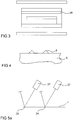
- the multilayer body 1 is arranged in a container 17 in the manner described above ( FIG. 2 ).
- the lid 18 and the bottom 19 are formed by the transparent bodies 5 and 12.
- a lateral wall 20 of the container 17 is made of carbon fiber reinforced carbon (CFC).
- the multi-layer body on the bottom plate of the container is filled with the process gas and sealed. Thereafter, the tempering takes place at a tempering of 5 ° C / s, the energy source 7 and 11 are controlled separately.
- Another embodiment is characterized in that an energy transmitter 26 is integrated in the box ( Figure 3).
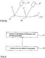
- the following control loop is used for the energy source 7:
- a lateral actual temperature profile of the transparent body 5 is measured with a pyrometer in the form of an infrared sensor of suitable wavelength. Due to the overlay of the multilayer body, the temperature profile of the carrier layer 2 can be determined by means of a calibration from the temperature profile of the transparency body. By a control algorithm on the actual and desired value of the temperature of the transparency body, a control signal is determined with which the radiation power of the energy source 7 is controlled.
- a controlled variable for a control circuit for controlling the energy source 11 is a transient bending 21 of the carrier layer 2.
- the bending 21 is measured by laser interferometry on the substrate side 22 or layer side 23. Measuring points are the substrate center 24 and a corner 25 of the multilayer body. In the case of laser interferometry, the change in distance caused by bending is measured and from this the control signal for the associated energy source is determined.
- the controlled variable for the energy source 11 is the temperature of the transparent body 12.
- FIG. 7 Another embodiment is in FIG. 7 indicated.
- the container 17 has gas openings in the form of a gas inlet 31 and a gas outlet 32. These openings have, for example, a closable valve which is closed after completion of the gas exchange. During transport of the container 17 with the multi-layer body 1 to the next process zone, the valve is closed.
- One of the process zones is a heating zone.
- the heating zone consists of two Arrays of halogen lamps. With the transport of the container (with transparent body) in the heating zone between the two arrays, the device for tempering is generated.
- FIG. 7 Another embodiment is also in FIG. 7 indicated.
- the entire device is in a processing chamber 30, which can be evacuated and filled with a specific gas.
- FIGS. 8a and 8b is the principle of a continuous process indicated by means of an inline system.
- the entire in-line system is arranged in the processing chamber 30 (FIG. FIG. 8a ).
- a different process step is performed.
- the container 17 is filled with the process gas and heated.
- the process zone 34 the container 17 is evacuated and cooled.
- each of the process zones 33 and 34 is arranged in a separate, separate process chamber 301 to 304 (FIG. FIG. 8b ).
- the inline system is distributed over several process chambers.
- the process chambers are provided with locks through which the containers enter the process chambers.
- FIG. 9a shows a cross section of the container 17 in the processing mode.
- the container 17 has a lid 18 in the form of a transparent body 12.
- the bottom 19 is made of a highly absorbent material.
- the material is graphite in one embodiment.
- a lateral wall 20 of the container 17 is a frame of the container 17 made of CFC.
- Gas inlet 31 and gas outlet 32 are integrated in the lateral wall of the container.
- Self-closing valves 40 are also integrated into the lateral wall 20. With these valves, the gas openings 31 and 32 for evacuating the container or filling the container with a gas to be opened or closed.
- a coupling unit 42 of the container of the process zone 33 is also integrated into the lateral wall.
- the coupling unit 42 may be designed, for example, as a cone-shaped opening. With this opening, the container 17 is placed on an inversely shaped to opening coupling unit 41 of the process zones. Gas lines 43 are integrated in the coupling units 41 and 42. If the container is arranged in this way with, for example, the process zone 33, for example, during this stage of the process, any process gas can be introduced or discharged or the processing container can be evacuated and purged with inert gas. In the illustrated form, the docking units 42 of the container 17 and the processing zone 33 serve to establish a process gas atmosphere.
- the zone 34 may, for example, be provided with a further coupling unit which, for example, reloads used processing gas or introduces a new processing gas.
Landscapes
- Physics & Mathematics (AREA)
- Thermal Sciences (AREA)
- Re-Forming, After-Treatment, Cutting And Transporting Of Glass Products (AREA)
- Laminated Bodies (AREA)
- Chemical Vapour Deposition (AREA)
- Recrystallisation Techniques (AREA)
- Photovoltaic Devices (AREA)
- Physical Vapour Deposition (AREA)
Claims (17)
- Dispositif pour tempérer un corps multicouche (1), qui présente une première couche (2, 3, 4) et au moins une deuxième couche (2, 3, 4), par l'absorption d'une quantité d'énergie à travers le corps multicouche (1) avec une absorption d'une première portion de la quantité d'énergie par le biais de la première couche (2, 3, 4) et une absorption d'une deuxième portion de la quantité d'énergie par le biais de la deuxième couche (2, 3, 4), présentant- au moins une source d'énergie (7, 11) de la quantité d'énergie,
où- une première et au moins une deuxième source d'énergie sont disponibles,- au moins l'une des sources d'énergie (7, 11) présente une absorption d'un rayonnement électromagnétique spécifique (13) avec un champ de rayonnement (9, 15),- au moins l'une des couches (2, 4) présente une absorption spécifique des rayonnements électromagnétiques (8, 13),- la première couche (2) entre la première source d'énergie (7) et la deuxième couche (4) et la deuxième couche (4) entre la deuxième source d'énergie (11) et la première couche (2) peuvent être disposées de telle manière que la couche (2, 4) avec l'absorption des rayonnements électromagnétiques (8, 13) se situe dans le champ de rayonnement (9, 15), et- au moins un corps de transparence optiquement semi-transparent (5, 12) au rayonnement électromagnétique (8, 13) est agencé dans le champ de rayonnement (9, 15) entre la source d'énergie (7, 11) avec le champ de rayonnement (9, 15) et la couche (2, 4), qui présente l'absorption des rayonnements électromagnétiques (8, 13), où le corps de transparence (5, 12), présente un matériau en vitrocéramique, où le corps de transparence (5, 12) forme le contour (18, 19, 20) d'un réservoir (17) pour maintenir le corps multicouche (1) lors de la trempe, où le contour est un couvercle (18) et un fond (19) du réservoir (17), où le corps multicouche (1) repose avec une couche directement sur le corps de transparence du fond (19). - Dispositif selon la revendication 1, où au moins un transmetteur d'énergie (26) pour la transmission de la quantité d'énergie sur le corps multicouche (1) est fourni, où le transmetteur d'énergie (26) absorbe le rayonnement électromagnétique et le transforme en rayonnement thermique qui est absorbé par la couche (2, 4).
- Dispositif selon la revendication 1 ou 2, où le corps de transparence (5, 12) présente une variété d'écarteurs (6), contre lesquels le corps multicouche (1) peut être appliqué, où les écarteurs (6) sont répartis de manière uniforme entre la couche du corps multicouche et touchant le corps de transparence pour l'homogénéisation de la distribution de la température latérale du corps multicouche (1).
- Dispositif selon la revendication 3, où les entretoises (6) présente un matériel sélectionné parmi le groupe constitué de verre et/ou vitrocéramique.
- Dispositif selon la revendication 1, où le réservoir (17) possède au moins une ouverture de gaz (31, 32) pour l'évacuation du réservoir et/ou le remplissage du réservoir d'un gaz de processus.
- Dispositif selon la revendication 5, où l'ouverture de gaz (31, 32) du réservoir (17) possède une unité de couplage (42) pour coupler le réservoir (17) sur une unité de couplage (41) d'une zone de processus (33, 34), où le réservoir (17) est maintenu dans la zone de processus (33, 34) au moyen de l'unité de couplage (42) ou peut être déplacé de zone de processus (33, 34) en zone de processus (33, 34).
- Dispositif selon la revendication 6, où le réservoir (17) est maintenu par le biais d'une unité de couplage (42) dans la zone de processus (33, 34) dans un processus continu pour la réalisation d'une étape de processus et est associé à une unité, de manière à pouvoir remplir le réservoir (17) de gaz ou l'évacuer.
- Dispositif selon l'une des revendications 1 à 7, où le dispositif est disposé dans une chambre de traitement (30, 301, 302, 303, 304) sélectionnée parmi le groupe constitué de chambre à vide, chambre à atmosphère et/ou chambre à haute pression.
- Dispositif selon l'une des revendications 1 à 8, où le corps de transparence (5, 12) et/ou le transmetteur d'énergie (26), et/ou le réservoir (17) et/ou la chambre de traitement présente un matériau, qui est inerte par rapport au gaz de processus (16).
- Dispositif selon l'une des revendications 1 à 9, où au moins une installation (27) est fournie pour la détection d'une quantité (21), d'au moins un paramètre physique dépendant de la trempe du dispositif pour le réglage de la première et de la deuxième portion de la quantité d'énergie.
- Dispositif selon la revendication 10, où le paramètre représente une déformation du corps multicouche.
- Procédure pour tempérer un corps multicouche, qui présente une première et au moins une deuxième couche, par l'absorption d'une quantité d'énergie à travers le corps multicouche avec une absorption d'une première portion de la quantité d'énergie par le biais de la première couche et une absorption d'une deuxième portion de la quantité d'énergie par le biais de la deuxième couche, où au moins une source d'énergie est utilisée pour fournir la quantité d'énergie au corps multicouche, en utilisant un dispositif selon l'une des revendications 1 à 11 comprenant les étapes suivantes :a) disposition du corps multicouche entre une première et au moins une deuxième source d'énergie,- ainsi la première couche est disposée entre la première source d'énergie et la deuxième couche et la deuxième couche entre la deuxième source d'énergie et la première couche- où au moins une source d'énergie est utilisée comme source d'énergie pour un rayonnement électromagnétique spécifique avec un champ de rayonnement,- et au moins une des couches absorbe le rayonnement électromagnétique et est disposé dans le champ de rayonnementet disposition d'un corps de transparence en vitrocéramique dans le champ de rayonnement de la source d'énergie entre la source d'énergie et la couche qui se trouve dans le champ de rayonnement de la source d'énergie et absorbe le rayonnement électromagnétique spécifique, où le corps de transparence (5, 12) forme un contour (18, 19, 20) d'un réservoir (17) pour maintenir le corps multicouche (1) lors de la trempe, où le contour est un couvercle (18) et un fond (19) du réservoir (17), où le corps multicouche (1) repose avec une couche directement sur le corps de transparence du fond (19).b) trempe du corps multicouche, où le corps de transparence absorbe une certaine quantité d'énergie pour la trempe et dirige la quantité d'énergie jusqu'à la couche reposant sur le fond par la conduction et la radiation de chaleur.
- Procédé selon la revendication 12, où au moins un matériau de l'une des couches du corps multicouche est sélectionné parmi le groupe constitué de verre, vitrocéramique, céramique, plastique et/ou métal.
- Procédé selon l'une des revendications 12 ou 13, où une détection d'une mesure dépendant de la trempe d'un paramètre physique du dispositif pour le réglage de l'absorption de la quantité d'énergie au cours de la trempe et un réglage de la quantité d'énergie sont effectués au cours de la trempe.
- Procédé selon l'une des revendications 12 à 14, où au moins une couche (2, 3, 4) est mise en contact avec un gaz de procédé (16).
- Procédé selon l'une des revendications 12 à 15, où la procédure est effectuée en tant qu'étape de procédure (33, 34) dans une procédure continue ou une procédure presque continue avec au moins deux étapes de procédure.
- Procédé selon l'une des revendications 12 à 16, où un corps multicouche est fabriqué avec une première couche en au moins un matériau choisi parmi le groupe constitué de cuivre, indium, gallium, soufre et/ou sélénium et une deuxième couche en verre, où une dimension du corps multicouche est sélectionnée dans une zone située entre 0,3 m et 5 m.
Applications Claiming Priority (3)
| Application Number | Priority Date | Filing Date | Title |
|---|---|---|---|
| DE19936081A DE19936081A1 (de) | 1999-07-30 | 1999-07-30 | Vorrichtung und Verfahren zum Temperieren eines Mehrschichtkörpers, sowie ein unter Anwendung des Verfahrens hergestellter Mehrschichtkörper |
| DE19936081 | 1999-07-30 | ||
| PCT/DE2000/002523 WO2001009961A2 (fr) | 1999-07-30 | 2000-07-31 | Dispositif et procede pour l'equilibrage de temperature d'un corps multicouche et corps multicouche correspondant |
Publications (2)
| Publication Number | Publication Date |
|---|---|
| EP1258043A2 EP1258043A2 (fr) | 2002-11-20 |
| EP1258043B1 true EP1258043B1 (fr) | 2018-07-18 |
Family
ID=7916741
Family Applications (1)
| Application Number | Title | Priority Date | Filing Date |
|---|---|---|---|
| EP00962177.2A Expired - Lifetime EP1258043B1 (fr) | 1999-07-30 | 2000-07-31 | Dispositif et procede pour l'equilibrage de temperature d'un corps multicouche |
Country Status (8)
| Country | Link |
|---|---|
| US (2) | US6717112B1 (fr) |
| EP (1) | EP1258043B1 (fr) |
| JP (1) | JP5361106B2 (fr) |
| CN (1) | CN1263166C (fr) |
| AU (1) | AU781422B2 (fr) |
| DE (1) | DE19936081A1 (fr) |
| ES (1) | ES2691644T3 (fr) |
| WO (1) | WO2001009961A2 (fr) |
Families Citing this family (26)
| Publication number | Priority date | Publication date | Assignee | Title |
|---|---|---|---|---|
| FR2846786B1 (fr) * | 2002-11-05 | 2005-06-17 | Procede de recuit thermique rapide de tranches a couronne | |
| DE10260672A1 (de) * | 2002-12-23 | 2004-07-15 | Mattson Thermal Products Gmbh | Verfahren und Vorrichtung zum thermischen Behandeln von scheibenförmigen Substraten |
| DE102005062977B3 (de) * | 2005-12-28 | 2007-09-13 | Sulfurcell Solartechnik Gmbh | Verfahren und Vorrichtung zur Umsetzung metallischer Vorläuferschichten zu Chalkopyritschichten von CIGSS-solarzellen |
| US8389852B2 (en) * | 2006-02-22 | 2013-03-05 | Guardian Industries Corp. | Electrode structure for use in electronic device and method of making same |
| EP1855324A1 (fr) * | 2006-05-12 | 2007-11-14 | Applied Materials GmbH & Co. KG | Substrate de type vitroceramique |
| DE102008022784A1 (de) | 2008-05-08 | 2009-11-12 | Avancis Gmbh & Co. Kg | Vorrichtung und Verfahren zum Tempern von Gegenständen in einer Behandlungskammer |
| US8314369B2 (en) * | 2008-09-17 | 2012-11-20 | Applied Materials, Inc. | Managing thermal budget in annealing of substrates |
| US20100068898A1 (en) | 2008-09-17 | 2010-03-18 | Stephen Moffatt | Managing thermal budget in annealing of substrates |
| KR20110097908A (ko) * | 2008-11-28 | 2011-08-31 | 볼커 프로브스트 | 반도체 층 또는 원소 셀레늄 및/또는 황으로 처리된 코팅 기판, 특히 평면 기판의 제조 방법 |
| TWI418047B (zh) * | 2009-01-07 | 2013-12-01 | 財團法人工業技術研究院 | Ib-iiia-via2化合物半導體薄膜之製造裝置 |
| US20100304527A1 (en) * | 2009-03-03 | 2010-12-02 | Peter Borden | Methods of thermal processing a solar cell |
| CN102473607A (zh) * | 2009-08-06 | 2012-05-23 | 住友电气工业株式会社 | 膜沉积装置 |
| DE102009053532B4 (de) * | 2009-11-18 | 2017-01-05 | Centrotherm Photovoltaics Ag | Verfahren und Vorrichtung zur Herstellung einer Verbindungshalbleiterschicht |
| DE102009047483A1 (de) | 2009-12-04 | 2011-06-09 | Sulfurcell Solartechnik Gmbh | Vorrichtung und Verfahren zur Erzeugung von Chalkopyrit-Absorberschichten in Solarzellen |
| DE102010008084A1 (de) | 2010-02-15 | 2011-08-18 | Leybold Optics GmbH, 63755 | Vorrichtung zur thermischen Behandlung von Substraten |
| US20110203655A1 (en) * | 2010-02-22 | 2011-08-25 | First Solar, Inc. | Photovoltaic device protection layer |
| EP2360720A1 (fr) * | 2010-02-23 | 2011-08-24 | Saint-Gobain Glass France | Dispositif de positionnement d'au moins deux objets, agencements, notamment agencements de corps multicouches, installation de traitement, notamment pour la sélénisation d'objets, procédé de positionnement d'au moins deux objets |
| TW201203584A (en) | 2010-07-02 | 2012-01-16 | Adpv Technology Ltd | Rapid thermal process heating system and method thereof |
| ES2858471T3 (es) * | 2012-07-19 | 2021-09-30 | Cnbm Bengbu Design & Res Institute For Glass Industry Co Ltd | Prevención de deformación de vidrio en procedimientos térmicos |
| DE102015016002A1 (de) * | 2015-12-10 | 2017-06-14 | Centrotherm Photovoltaics Ag | Verfahren und Vorrichtung zum thermischen Behandeln von Substraten sowie Aufnahmeeinheit für Substrate |
| EP3690962A1 (fr) | 2019-01-31 | 2020-08-05 | (CNBM) Bengbu Design & Research Institute for Glass Industry Co., Ltd. | Agencement, dispositif et procédé de traitement thermique d'un corps multicouche |
| DE102020208184B4 (de) * | 2020-06-30 | 2025-02-20 | Singulus Technologies Aktiengesellschaft | Heizsystem und Verfahren zum Aufheizen von großflächigen Substraten |
| DE102021004175B3 (de) | 2021-08-13 | 2022-12-01 | Singulus Technologies Aktiengesellschaft | Abstandsvorrichtung für Heizsystem zum Aufheizen von großflächigen Substraten, Heizsystem und Aufheizverfahren |
| CA3143926A1 (fr) * | 2021-08-19 | 2023-02-19 | James William Masten | Procede thermophysique pour le traitement thermique du verre |
| EP4341987B1 (fr) | 2022-06-23 | 2025-06-18 | Cnbm Research Institute For Advanced Glass Materials Group Co., Ltd. | Dispositif de traitement thermique à économie d'énergie pour substrat métallique dans un gaz corrosif |
| CN119803083B (zh) * | 2025-01-02 | 2025-11-11 | 中冶长天国际工程有限责任公司 | 一种分层布料烧结及冷却的方法和系统 |
Family Cites Families (17)
| Publication number | Priority date | Publication date | Assignee | Title |
|---|---|---|---|---|
| JPS57183041A (en) * | 1981-05-06 | 1982-11-11 | Nec Corp | Annealing method for chemical semiconductor |
| US4976996A (en) * | 1987-02-17 | 1990-12-11 | Lam Research Corporation | Chemical vapor deposition reactor and method of use thereof |
| JPS63257221A (ja) * | 1987-04-14 | 1988-10-25 | Nec Corp | ランプアニ−ル装置 |
| JPH01179309A (ja) * | 1987-12-30 | 1989-07-17 | Tokyo Electron Ltd | 加熱法 |
| US5011794A (en) * | 1989-05-01 | 1991-04-30 | At&T Bell Laboratories | Procedure for rapid thermal annealing of implanted semiconductors |
| JPH0812847B2 (ja) * | 1991-04-22 | 1996-02-07 | 株式会社半導体プロセス研究所 | 半導体製造装置及び半導体装置の製造方法 |
| JP3002013B2 (ja) * | 1991-06-04 | 2000-01-24 | 松下技研株式会社 | 薄膜および多層膜の製造方法およびその製造装置 |
| WO1994007269A1 (fr) | 1992-09-22 | 1994-03-31 | Siemens Aktiengesellschaft | Procede rapide de realisation d'un semi-conducteur en chalcopyrite sur un substrat |
| JPH0778830A (ja) * | 1993-09-07 | 1995-03-20 | Hitachi Ltd | 半導体製造装置 |
| JP2825756B2 (ja) * | 1994-05-27 | 1998-11-18 | シャープ株式会社 | 薄膜el素子の製造方法および製造装置 |
| JP2875768B2 (ja) * | 1994-11-30 | 1999-03-31 | 新日本無線株式会社 | 半導体基板の熱処理方法 |
| US5861609A (en) * | 1995-10-02 | 1999-01-19 | Kaltenbrunner; Guenter | Method and apparatus for rapid thermal processing |
| US5851929A (en) * | 1996-01-04 | 1998-12-22 | Micron Technology, Inc. | Controlling semiconductor structural warpage in rapid thermal processing by selective and dynamic control of a heating source |
| DE19711702C1 (de) * | 1997-03-20 | 1998-06-25 | Siemens Ag | Anordnung zur Bearbeitung einer Substratscheibe und Verfahren zu deren Betrieb |
| GB9717182D0 (en) * | 1997-08-13 | 1997-10-22 | Glaverbel | Copper mirrors |
| US6173116B1 (en) * | 1997-12-19 | 2001-01-09 | U.S. Philips Corporation | Furnace for rapid thermal processing |
| US6171982B1 (en) * | 1997-12-26 | 2001-01-09 | Canon Kabushiki Kaisha | Method and apparatus for heat-treating an SOI substrate and method of preparing an SOI substrate by using the same |
-
1999
- 1999-07-30 DE DE19936081A patent/DE19936081A1/de not_active Ceased
-
2000
- 2000-07-31 WO PCT/DE2000/002523 patent/WO2001009961A2/fr not_active Ceased
- 2000-07-31 EP EP00962177.2A patent/EP1258043B1/fr not_active Expired - Lifetime
- 2000-07-31 US US10/048,419 patent/US6717112B1/en not_active Expired - Lifetime
- 2000-07-31 ES ES00962177.2T patent/ES2691644T3/es not_active Expired - Lifetime
- 2000-07-31 JP JP2001514489A patent/JP5361106B2/ja not_active Expired - Lifetime
- 2000-07-31 AU AU74020/00A patent/AU781422B2/en not_active Ceased
- 2000-07-31 CN CN00813743.9A patent/CN1263166C/zh not_active Expired - Lifetime
-
2003
- 2003-10-27 US US10/692,728 patent/US6884968B2/en not_active Expired - Lifetime
Non-Patent Citations (1)
| Title |
|---|
| None * |
Also Published As
| Publication number | Publication date |
|---|---|
| US6717112B1 (en) | 2004-04-06 |
| JP2003519441A (ja) | 2003-06-17 |
| WO2001009961A2 (fr) | 2001-02-08 |
| WO2001009961A3 (fr) | 2002-09-19 |
| AU781422B2 (en) | 2005-05-19 |
| DE19936081A1 (de) | 2001-02-08 |
| EP1258043A2 (fr) | 2002-11-20 |
| US6884968B2 (en) | 2005-04-26 |
| US20040087172A1 (en) | 2004-05-06 |
| AU7402000A (en) | 2001-02-19 |
| ES2691644T3 (es) | 2018-11-28 |
| CN1399798A (zh) | 2003-02-26 |
| JP5361106B2 (ja) | 2013-12-04 |
| CN1263166C (zh) | 2006-07-05 |
Similar Documents
| Publication | Publication Date | Title |
|---|---|---|
| EP1258043B1 (fr) | Dispositif et procede pour l'equilibrage de temperature d'un corps multicouche | |
| EP1277238B1 (fr) | Dispositif et procédé pour le recuit simultané de plusieurs produits fabriqués | |
| EP1277237B1 (fr) | Procédé et dispositif pour recuire au moins un élément à traiter | |
| EP2291868B1 (fr) | Dispositif et procédé de régulation de température d'objets dans une chambre de traitement | |
| EP2609617B1 (fr) | Dispositif et procédé de traitement thermique de plusieurs corps multicouches | |
| DE102009037299A1 (de) | Vorrichtung und Behandlungskammer zur thermischen Behandlung von Substraten | |
| WO2007077171A2 (fr) | Procede et installation de transformation de couches de precurseur metallique en couches de chalcopyrite de cellules solaires cigss | |
| KR20120123097A (ko) | 감소된 챔버 공간을 형성하는 장치 및 다층체의 위치 결정 방법 | |
| EP2875530B1 (fr) | Prévention du pliage de verre dans le cadre d'un procédé thermique | |
| DE102017003516A1 (de) | Beschichtungsvorrichtung und Verfahren zur reaktiven Dampfphasenabscheidung unter Vakuum auf einem Substrat | |
| DE4437361C2 (de) | Verfahren und Vorrichtung für die optische Schnellheizbehandlung empfindlicher elektronischer Bauelemente, insbesondere Halbleiterbauelemente | |
| EP2537175A1 (fr) | Dispositif de traitement thermique de substrats | |
| DE102009053532B4 (de) | Verfahren und Vorrichtung zur Herstellung einer Verbindungshalbleiterschicht | |
| EP2553136B1 (fr) | Procédé de remplissage d'une chambre d'évaporateur | |
| DE102008030679B4 (de) | Vorrichtung zur Diffusionsbehandlung von Werkstücken | |
| EP2369034B1 (fr) | Procédé de remplissage d'une chambre d'évaporateur de sélénium | |
| EP2870624A1 (fr) | Dispositif et procédé de traitement thermique d'un objet | |
| WO2015186899A1 (fr) | Procédé de fabrication d'une couche d'absorption de lumière pour cellule solaire en couches minces | |
| DE102015103577A1 (de) | Prozessieranordnung und Verfahren zum Kurzzeittempern einer Beschichtung auf einem lichtdurchlässigen Substrat | |
| DE102014200739A1 (de) | Lochblende mit optimiertem thermischem Emissionsverhalten |
Legal Events
| Date | Code | Title | Description |
|---|---|---|---|
| PUAI | Public reference made under article 153(3) epc to a published international application that has entered the european phase |
Free format text: ORIGINAL CODE: 0009012 |
|
| 17P | Request for examination filed |
Effective date: 20020114 |
|
| AK | Designated contracting states |
Kind code of ref document: A2 Designated state(s): AT BE CH CY DE DK ES FI FR GB GR IE IT LI LU MC NL PT SE |
|
| RAP1 | Party data changed (applicant data changed or rights of an application transferred) |
Owner name: SHELL SOLAR GMBH |
|
| RAP1 | Party data changed (applicant data changed or rights of an application transferred) |
Owner name: SHELL ERNEUERBARE ENERGIEN GMBH |
|
| RAP1 | Party data changed (applicant data changed or rights of an application transferred) |
Owner name: SAINT-GOBAIN GLASS FRANCE S.A. |
|
| 17Q | First examination report despatched |
Effective date: 20120727 |
|
| RIC1 | Information provided on ipc code assigned before grant |
Ipc: B32B 38/00 20060101ALI20171019BHEP Ipc: H01L 31/032 20060101ALI20171019BHEP Ipc: H01L 31/0749 20120101ALI20171019BHEP Ipc: H01L 31/18 20060101AFI20171019BHEP |
|
| GRAP | Despatch of communication of intention to grant a patent |
Free format text: ORIGINAL CODE: EPIDOSNIGR1 |
|
| STAA | Information on the status of an ep patent application or granted ep patent |
Free format text: STATUS: GRANT OF PATENT IS INTENDED |
|
| INTG | Intention to grant announced |
Effective date: 20171201 |
|
| RIN1 | Information on inventor provided before grant (corrected) |
Inventor name: PROBST, VOLKER |
|
| GRAS | Grant fee paid |
Free format text: ORIGINAL CODE: EPIDOSNIGR3 |
|
| GRAA | (expected) grant |
Free format text: ORIGINAL CODE: 0009210 |
|
| STAA | Information on the status of an ep patent application or granted ep patent |
Free format text: STATUS: THE PATENT HAS BEEN GRANTED |
|
| REG | Reference to a national code |
Ref country code: DE Ref legal event code: R081 Ref document number: 50016503 Country of ref document: DE Owner name: (CNBM) BENGBU DESIGN & RESEARCH INSTITUTE FOR , CN Free format text: FORMER OWNER: SIEMENS AKTIENGESELLSCHAFT, 80333 MUENCHEN, DE |
|
| AK | Designated contracting states |
Kind code of ref document: B1 Designated state(s): AT BE CH CY DE DK ES FI FR GB GR IE IT LI LU MC NL PT SE |
|
| REG | Reference to a national code |
Ref country code: GB Ref legal event code: FG4D Free format text: NOT ENGLISH |
|
| REG | Reference to a national code |
Ref country code: CH Ref legal event code: EP |
|
| REG | Reference to a national code |
Ref country code: IE Ref legal event code: FG4D Free format text: LANGUAGE OF EP DOCUMENT: GERMAN |
|
| REG | Reference to a national code |
Ref country code: DE Ref legal event code: R096 Ref document number: 50016503 Country of ref document: DE |
|
| REG | Reference to a national code |
Ref country code: AT Ref legal event code: REF Ref document number: 1020281 Country of ref document: AT Kind code of ref document: T Effective date: 20180815 |
|
| REG | Reference to a national code |
Ref country code: NL Ref legal event code: MP Effective date: 20180718 |
|
| REG | Reference to a national code |
Ref country code: ES Ref legal event code: FG2A Ref document number: 2691644 Country of ref document: ES Kind code of ref document: T3 Effective date: 20181128 |
|
| PG25 | Lapsed in a contracting state [announced via postgrant information from national office to epo] |
Ref country code: NL Free format text: LAPSE BECAUSE OF FAILURE TO SUBMIT A TRANSLATION OF THE DESCRIPTION OR TO PAY THE FEE WITHIN THE PRESCRIBED TIME-LIMIT Effective date: 20180718 |
|
| PG25 | Lapsed in a contracting state [announced via postgrant information from national office to epo] |
Ref country code: FI Free format text: LAPSE BECAUSE OF FAILURE TO SUBMIT A TRANSLATION OF THE DESCRIPTION OR TO PAY THE FEE WITHIN THE PRESCRIBED TIME-LIMIT Effective date: 20180718 Ref country code: SE Free format text: LAPSE BECAUSE OF FAILURE TO SUBMIT A TRANSLATION OF THE DESCRIPTION OR TO PAY THE FEE WITHIN THE PRESCRIBED TIME-LIMIT Effective date: 20180718 Ref country code: GR Free format text: LAPSE BECAUSE OF FAILURE TO SUBMIT A TRANSLATION OF THE DESCRIPTION OR TO PAY THE FEE WITHIN THE PRESCRIBED TIME-LIMIT Effective date: 20181019 |
|
| REG | Reference to a national code |
Ref country code: CH Ref legal event code: PL |
|
| PG25 | Lapsed in a contracting state [announced via postgrant information from national office to epo] |
Ref country code: LU Free format text: LAPSE BECAUSE OF NON-PAYMENT OF DUE FEES Effective date: 20180731 |
|
| REG | Reference to a national code |
Ref country code: BE Ref legal event code: MM Effective date: 20180731 |
|
| REG | Reference to a national code |
Ref country code: DE Ref legal event code: R097 Ref document number: 50016503 Country of ref document: DE |
|
| PG25 | Lapsed in a contracting state [announced via postgrant information from national office to epo] |
Ref country code: MC Free format text: LAPSE BECAUSE OF FAILURE TO SUBMIT A TRANSLATION OF THE DESCRIPTION OR TO PAY THE FEE WITHIN THE PRESCRIBED TIME-LIMIT Effective date: 20180718 Ref country code: LI Free format text: LAPSE BECAUSE OF NON-PAYMENT OF DUE FEES Effective date: 20180731 Ref country code: CH Free format text: LAPSE BECAUSE OF NON-PAYMENT OF DUE FEES Effective date: 20180731 |
|
| REG | Reference to a national code |
Ref country code: IE Ref legal event code: MM4A |
|
| PLBE | No opposition filed within time limit |
Free format text: ORIGINAL CODE: 0009261 |
|
| STAA | Information on the status of an ep patent application or granted ep patent |
Free format text: STATUS: NO OPPOSITION FILED WITHIN TIME LIMIT |
|
| PG25 | Lapsed in a contracting state [announced via postgrant information from national office to epo] |
Ref country code: DK Free format text: LAPSE BECAUSE OF FAILURE TO SUBMIT A TRANSLATION OF THE DESCRIPTION OR TO PAY THE FEE WITHIN THE PRESCRIBED TIME-LIMIT Effective date: 20180718 Ref country code: BE Free format text: LAPSE BECAUSE OF NON-PAYMENT OF DUE FEES Effective date: 20180731 |
|
| 26N | No opposition filed |
Effective date: 20190423 |
|
| PG25 | Lapsed in a contracting state [announced via postgrant information from national office to epo] |
Ref country code: IE Free format text: LAPSE BECAUSE OF NON-PAYMENT OF DUE FEES Effective date: 20180731 |
|
| REG | Reference to a national code |
Ref country code: AT Ref legal event code: MM01 Ref document number: 1020281 Country of ref document: AT Kind code of ref document: T Effective date: 20180731 |
|
| REG | Reference to a national code |
Ref country code: DE Ref legal event code: R082 Ref document number: 50016503 Country of ref document: DE Representative=s name: SPLANEMANN PATENTANWAELTE PARTNERSCHAFT MBB, DE Ref country code: DE Ref legal event code: R081 Ref document number: 50016503 Country of ref document: DE Owner name: (CNBM) BENGBU DESIGN & RESEARCH INSTITUTE FOR , CN Free format text: FORMER OWNER: SAINT-GOBAIN GLASS FRANCE S.A., COURBEVOIE, FR |
|
| PGFP | Annual fee paid to national office [announced via postgrant information from national office to epo] |
Ref country code: ES Payment date: 20190826 Year of fee payment: 20 Ref country code: IT Payment date: 20190725 Year of fee payment: 20 Ref country code: FR Payment date: 20190729 Year of fee payment: 20 |
|
| REG | Reference to a national code |
Ref country code: ES Ref legal event code: PC2A Owner name: BENGBU DESIGN & RESEARCH INSTITUTE FOR GLASS INDUS Effective date: 20191106 |
|
| PG25 | Lapsed in a contracting state [announced via postgrant information from national office to epo] |
Ref country code: AT Free format text: LAPSE BECAUSE OF NON-PAYMENT OF DUE FEES Effective date: 20180731 |
|
| PGFP | Annual fee paid to national office [announced via postgrant information from national office to epo] |
Ref country code: GB Payment date: 20190729 Year of fee payment: 20 |
|
| REG | Reference to a national code |
Ref country code: GB Ref legal event code: 732E Free format text: REGISTERED BETWEEN 20191219 AND 20191224 |
|
| PGFP | Annual fee paid to national office [announced via postgrant information from national office to epo] |
Ref country code: DE Payment date: 20190930 Year of fee payment: 20 |
|
| PG25 | Lapsed in a contracting state [announced via postgrant information from national office to epo] |
Ref country code: PT Free format text: LAPSE BECAUSE OF FAILURE TO SUBMIT A TRANSLATION OF THE DESCRIPTION OR TO PAY THE FEE WITHIN THE PRESCRIBED TIME-LIMIT Effective date: 20180718 |
|
| PG25 | Lapsed in a contracting state [announced via postgrant information from national office to epo] |
Ref country code: CY Free format text: LAPSE BECAUSE OF FAILURE TO SUBMIT A TRANSLATION OF THE DESCRIPTION OR TO PAY THE FEE WITHIN THE PRESCRIBED TIME-LIMIT Effective date: 20180718 |
|
| REG | Reference to a national code |
Ref country code: DE Ref legal event code: R071 Ref document number: 50016503 Country of ref document: DE |
|
| REG | Reference to a national code |
Ref country code: GB Ref legal event code: PE20 Expiry date: 20200730 |
|
| PG25 | Lapsed in a contracting state [announced via postgrant information from national office to epo] |
Ref country code: GB Free format text: LAPSE BECAUSE OF EXPIRATION OF PROTECTION Effective date: 20200730 |
|
| REG | Reference to a national code |
Ref country code: ES Ref legal event code: FD2A Effective date: 20201126 |
|
| PG25 | Lapsed in a contracting state [announced via postgrant information from national office to epo] |
Ref country code: ES Free format text: LAPSE BECAUSE OF EXPIRATION OF PROTECTION Effective date: 20200801 |