EP1258112B1 - Reconfiguration dans un reseau numerique - Google Patents
Reconfiguration dans un reseau numerique Download PDFInfo
- Publication number
- EP1258112B1 EP1258112B1 EP02715662A EP02715662A EP1258112B1 EP 1258112 B1 EP1258112 B1 EP 1258112B1 EP 02715662 A EP02715662 A EP 02715662A EP 02715662 A EP02715662 A EP 02715662A EP 1258112 B1 EP1258112 B1 EP 1258112B1
- Authority
- EP
- European Patent Office
- Prior art keywords
- node
- stations
- communicating
- network
- trigger
- Prior art date
- Legal status (The legal status is an assumption and is not a legal conclusion. Google has not performed a legal analysis and makes no representation as to the accuracy of the status listed.)
- Expired - Lifetime
Links
Images


Classifications
-
- H—ELECTRICITY
- H04—ELECTRIC COMMUNICATION TECHNIQUE
- H04L—TRANSMISSION OF DIGITAL INFORMATION, e.g. TELEGRAPHIC COMMUNICATION
- H04L12/00—Data switching networks
- H04L12/28—Data switching networks characterised by path configuration, e.g. LAN [Local Area Networks] or WAN [Wide Area Networks]
- H04L12/2803—Home automation networks
- H04L12/2805—Home Audio Video Interoperability [HAVI] networks
-
- H—ELECTRICITY
- H04—ELECTRIC COMMUNICATION TECHNIQUE
- H04L—TRANSMISSION OF DIGITAL INFORMATION, e.g. TELEGRAPHIC COMMUNICATION
- H04L12/00—Data switching networks
- H04L12/28—Data switching networks characterised by path configuration, e.g. LAN [Local Area Networks] or WAN [Wide Area Networks]
- H04L12/40—Bus networks
-
- H—ELECTRICITY
- H04—ELECTRIC COMMUNICATION TECHNIQUE
- H04L—TRANSMISSION OF DIGITAL INFORMATION, e.g. TELEGRAPHIC COMMUNICATION
- H04L12/00—Data switching networks
- H04L12/28—Data switching networks characterised by path configuration, e.g. LAN [Local Area Networks] or WAN [Wide Area Networks]
- H04L12/2803—Home automation networks
- H04L12/2807—Exchanging configuration information on appliance services in a home automation network
-
- H—ELECTRICITY
- H04—ELECTRIC COMMUNICATION TECHNIQUE
- H04L—TRANSMISSION OF DIGITAL INFORMATION, e.g. TELEGRAPHIC COMMUNICATION
- H04L12/00—Data switching networks
- H04L12/28—Data switching networks characterised by path configuration, e.g. LAN [Local Area Networks] or WAN [Wide Area Networks]
- H04L12/40—Bus networks
- H04L12/40052—High-speed IEEE 1394 serial bus
- H04L12/40078—Bus configuration
-
- H—ELECTRICITY
- H04—ELECTRIC COMMUNICATION TECHNIQUE
- H04L—TRANSMISSION OF DIGITAL INFORMATION, e.g. TELEGRAPHIC COMMUNICATION
- H04L12/00—Data switching networks
- H04L12/28—Data switching networks characterised by path configuration, e.g. LAN [Local Area Networks] or WAN [Wide Area Networks]
- H04L12/40—Bus networks
- H04L12/40052—High-speed IEEE 1394 serial bus
- H04L12/40117—Interconnection of audio or video/imaging devices
-
- H—ELECTRICITY
- H04—ELECTRIC COMMUNICATION TECHNIQUE
- H04L—TRANSMISSION OF DIGITAL INFORMATION, e.g. TELEGRAPHIC COMMUNICATION
- H04L12/00—Data switching networks
- H04L12/64—Hybrid switching systems
- H04L12/6418—Hybrid transport
-
- H—ELECTRICITY
- H04—ELECTRIC COMMUNICATION TECHNIQUE
- H04L—TRANSMISSION OF DIGITAL INFORMATION, e.g. TELEGRAPHIC COMMUNICATION
- H04L61/00—Network arrangements, protocols or services for addressing or naming
- H04L61/09—Mapping addresses
- H04L61/10—Mapping addresses of different types
-
- H—ELECTRICITY
- H04—ELECTRIC COMMUNICATION TECHNIQUE
- H04L—TRANSMISSION OF DIGITAL INFORMATION, e.g. TELEGRAPHIC COMMUNICATION
- H04L61/00—Network arrangements, protocols or services for addressing or naming
- H04L61/30—Managing network names, e.g. use of aliases or nicknames
-
- H—ELECTRICITY
- H04—ELECTRIC COMMUNICATION TECHNIQUE
- H04L—TRANSMISSION OF DIGITAL INFORMATION, e.g. TELEGRAPHIC COMMUNICATION
- H04L61/00—Network arrangements, protocols or services for addressing or naming
- H04L61/30—Managing network names, e.g. use of aliases or nicknames
- H04L61/3005—Mechanisms for avoiding name conflicts
-
- H—ELECTRICITY
- H04—ELECTRIC COMMUNICATION TECHNIQUE
- H04L—TRANSMISSION OF DIGITAL INFORMATION, e.g. TELEGRAPHIC COMMUNICATION
- H04L61/00—Network arrangements, protocols or services for addressing or naming
- H04L61/50—Address allocation
- H04L61/5038—Address allocation for local use, e.g. in LAN or USB networks, or in a controller area network [CAN]
-
- H—ELECTRICITY
- H04—ELECTRIC COMMUNICATION TECHNIQUE
- H04L—TRANSMISSION OF DIGITAL INFORMATION, e.g. TELEGRAPHIC COMMUNICATION
- H04L61/00—Network arrangements, protocols or services for addressing or naming
- H04L61/50—Address allocation
- H04L61/5076—Update or notification mechanisms, e.g. DynDNS
-
- H—ELECTRICITY
- H04—ELECTRIC COMMUNICATION TECHNIQUE
- H04L—TRANSMISSION OF DIGITAL INFORMATION, e.g. TELEGRAPHIC COMMUNICATION
- H04L61/00—Network arrangements, protocols or services for addressing or naming
- H04L61/50—Address allocation
- H04L61/5092—Address allocation by self-assignment, e.g. picking addresses at random and testing if they are already in use
-
- H—ELECTRICITY
- H04—ELECTRIC COMMUNICATION TECHNIQUE
- H04N—PICTORIAL COMMUNICATION, e.g. TELEVISION
- H04N21/00—Selective content distribution, e.g. interactive television or video on demand [VOD]
- H04N21/40—Client devices specifically adapted for the reception of or interaction with content, e.g. set-top-box [STB]; Operations thereof
- H04N21/43—Processing of content or additional data, e.g. demultiplexing additional data from a digital video stream; Elementary client operations, e.g. monitoring of home network or synchronising decoder's clock; Client middleware
- H04N21/436—Interfacing a local distribution network, e.g. communicating with another STB or one or more peripheral devices inside the home
- H04N21/43615—Interfacing a Home Network, e.g. for connecting the client to a plurality of peripherals
Definitions
- the invention relates to a method for executing a re-configuration in a self-configuring digital network after occurrence of a re-configuration trigger.
- a non-limiting example of such network is the Serial Bus Network IEEE 1394-1995 as discussed in International PCT Patent Application WO 00/23869.
- This standard allows a plug-and-play feature, and although originally intended for computer-based applications, has been introduced also into in-home consumer-electronic networks. Its prime definition level is the physical level.
- Various modifications and extensions to the standard have been implemented in Standards 1394A2000 and P1394.1.
- Still another feasible embodiment for the present invention is the USB bus standard.
- the invention relates to a method as recited in the preamble of independent Claim 1 hereinafter.
- the abstract of the above PCT reference recites that the controlling application utilizes so-called handle objects to reconfigure objects to dynamically enumerate and represent devices that are coupled to a serial bus network after a bus reset event.
- handle objects to reconfigure objects to dynamically enumerate and represent devices that are coupled to a serial bus network after a bus reset event.
- information about the characteristics of the devices within the network will be received.
- objects are generated that represent the various devices.
- Existing handle objects from a previous bus configuration are then compared to these newer objects. If a handle object would match such newer object, then a pointer value within the handle object will be changed to point to an address of the newer object.
- the handle object will preferably never be discarded, but is rather made invalid.
- EP 0 932 275 describes a method and system for providing a device identification mechanism for a HAVi network communicating via an IEEE 1394 network.
- a global unique identifier (GUID) is associated with each device.
- a low level driver constructs a GUID list of each device on the HAVi network. The order of the GUID list matches the physical identifiers assigned to the devices on the 1394 bus. The GUID list is re-built on reset of the 1394 bus. Although the physical identifiers can change on bus reset, the GUID values are constant and are used for device communication. Translations between GUIDs and physical identifiers are performed when certain information is required.
- the logical configuration of the network must be established again. In certain circumstances, this may require an inappropriately long time, inter alia, because certain stations may need to exchange a large amount of information with one or more other stations, and/or certain stations may feature a large inherent delay before they will be fully operational again.
- the inventor has recognized however, that one or more parts of the network could take up their respective operations again, even if certain other stations outside the part or parts in question were still busy with recuperating.
- the P1394.1 standard would even allow the forming of in-network clusters of node.
- the method of the present invention is defined by Claim 1.
- the necessity implies all that is necessary for proceeding with the ongoing operations of the network, including of coping with possible contingencies.
- the reference has indeed the transmitting of the device characteristics even to physical devices with which the transmitter station had not been cooperating. Waiting until completion thereof would clearly take an inappropriately long time.
- the invention also relates to a system arranged for implementing a method according to the present invention as claimed in Claim 6, and to an apparatus being arranged to operate as a node station in such system and as claimed in Claim 7. Further advantageous aspects of the invention are recited in dependent Claims.
- a digital network such as, but not being limited to, a home network, will generally consist of a set of nodes interconnected by point-to-point physical links.
- the nodes may represent various user functionality devices, such as audio and/or video components, security cameras, household appliances, antenna disk or other external link stations, and also system-level devices, such as subaltern networks.
- an initial event such as a bus reset
- the network will be reconfigured and a new logical view of the overall status of the network must be created. For each respective node, this logical view or topology map will comprise the relevant node itself, its interconnections, and such additional functional or other information of the relevant nodes as would be appropriate.
- nodes will collect this additional information for each particular logic node as being based on the identifier of that particular node.
- one or more of the nodes will store an overall logical view of the network. This overall view may be interrogated by other nodes according to need, until a next reconfiguration will occur. This new reconfiguration will then again cause the setting up of a new or amended overall logical view, which may then even be stored on a different node from before.
- the above initial event will cause an unstable situation in the network.
- Such unstable situation may be aggravated because various nodes will need respective different amounts of time to recover from the unstable situation, included therein a time period that is necessary for the generating or receiving of the additional information, such as functional information, on a per node basis.
- This functional information may by way of example include various operational parameters or interface definitions.
- the heavy bus traffic necessary for effecting this communication may contribute to the system instability, because in principle, each node would need to have its own, possibly partial knowledge of the logical view of the overall network.
- Such acquiring of the overall view may in fact be executed in that a node would interrogate the node that stores the topology map.
- Another feasible stratagem were that each node would itself compose such logical map view.
- the latter procedure may result in unnecessary waste of bandwidth due to failed transactions requests to a node that is not yet ready for communicating, or in incomplete and/or inconsistent logical views at several nodes. There will in fact be no guarantee that all preliminary logical views will
- the present invention applies selective topology, which allows the network to stabilize in a felicitous manner. Immediately after the event leading to the bus reset or trigger signal, the present invention will minimize the amount of communication. In fact, the inventor has recognized that it is generally not necessary to update all functionality information. The additional or functional information that uniquely identifies the physical node and its appropriate properties will always remain unchanged as long as the associated device remains in place, although its mapping on the logical identifier may be changed. It is thus proposed to only update the required information of the communicating nodes. Each node only has to store the additional information of the node or nodes it has a communcation relation with. After the initial event, the inventive idea is to take no actions on the network, but to only mark all available mappings as invalid.
- This marking will indicate that the stored information could still be up-to-date indeed, and that it might be re-used in the future. If the node in question has to communicate with another node marked invalid , for the first time after the initial event, the former will check whether the original mapping of the node on a particular device is still valid, through an information query to the corresponding node, and it will only selectively update the mapping according to necessity. If the mapping is invalid however, such as through removing or replacing of an apparatus, a network-wide query will be issued instead to update the mapping.
- the Selective Topology Mapping according to the present invention will allow the network to stabilize (it will delay the first network access), reduce the number of network accesses (use less bandwidth), and generally, increase overall efficiency.
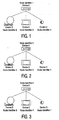
- Figure 1 illustrates a logical node mapping of a network before an initial event.
- device A is a video storage apparatus
- device B a disc antenna station
- device C a television set
- device D a camera.
- the logical node identifiers have been indicated for each device or physical node.
- Device A with node identifier #1 stores the overall logical view of the network.
- Devices A and C are maintaining a video stream, for example, while running and displaying a video title. Accessing in the network is always based on the logical node identifier.
- the arrangement embodiment carries the assumption that device D will need relatively much time for recovering from the initial event, and in such interval would not be available to supply information to any of the other devices.
- the overall network topology will not be complete before the termination of the above recovery time.
- the overall network could become operational much faster, i.e., as soon as devices A and C will have checked that their respective mappings have been unchanged, or rather, found out enough details on their respective whereabouts and functionality. The same would apply to the replacing of one of the two devices, as far as this replacing would not influence the mode of operation.
- another video storage apparatus would need the same cassette and would have to be controlled in the same manner as its predecessor.
- Figure 2 illustrates a first logical node mapping of a network as amended after an initial event that were to generate the described trigger signal, but with the devices located as in Figure 1. As shown, device A has maintained its logical identifier, whereas all other devices or nodes have gotten different logical identifiers from the situation in Figure 1.
- Figure 3 illustrates a second logical node mapping of a network after a similar initial event as in Figure 2, but for the remainder, unchanged. Again, various devices have gotten different identifiers.
- Figure 4 illustrates a general binary tree network for use with the invention; no configuration with loops will be considered.
- root node 120 has a map of the logical network.
- other nodes 122 through 140 are interconnected in such manner that each node has zero, one or two connected nodes in a next higher network layer.
- Nodes 124, 126, 134, 136 and 140 are leaf nodes in that they connect no node at a higher layer level. In principle, higher numbers for the interconnection multiplicity are feasible. In practice, any network size could do.
- the same network may also be represented by rearranging the nodes into a different configuration, leaving the various connections unchanged.
- Figure 5 illustrates a flow chart of the operations executed according to an exemplary embodiment of the present invention.
- the operation starts, and all necessary hardware and software facilities are assigned.
- a Bus Reset signal is detected. Of course, such detecting may be effected through circling in a waiting loop, and this detecting would then represent a "detect-YES" exit of the loop.
- all ongoing communication operations are interrupted.
- the pre-existing communication pattern is recognized by the node in question and saved in a local storage facility. This will include all ongoing communications as well as communication relations that for the moment had been inactive, but could become active if required.
- all mappings of the logical nodes on the physical nodes are made invalid.
- the various nodes will start undertaking to effect a new mapping pattern that would be appropriate for the overall configuration. Such undertaking may be based on the node's self-identifier assigned under the 1394 standard, and be executed first on the tree level of node itself. A particular device would first try to monopolize the associated tree level through using a timer functionality and its self-identifier, and tentatively assign to itself a logical mapping number. This number will then be broadcast on that tree level, for consent by the other connected nodes or otherwise. In block 32, this consent (Y), or dissent (N) is detected. Next, in block 34, the mapping is stored. To this effect, the HAVI organization must find out all changes that have been effected and retrieve the associated information, by putting the appropriate questions to all devices concerned. This operation then proceeds for the other nodes on the tree level in question, which has not been explicitly shown, and also on the other tree levels. If the mapping is unrestorable, a network-wide query is undertaken for a replacement target node for such mapping.
- the device in question will detect wether all mappings for letting the device in question resume its communication pattern have succeeded. If not yet (N), the device reverts to block 32 to find such other mapping.
- N the device reverts to block 32 to find such other mapping.
- the mapping patterns of Figures 1-3 after a bus reset, two stations donot have to find any outside mapping at all, whereas the other two stations should each find only one external mapping before being able to resume operations.
- the devices After completion of the local mapping (block 36 YES), the devices will transfer their functionality information to those other stations that need to know but have not yet gotten the information in question.
- a READY? detection is executed. If not, the system reverts to block 32. Such case may for example be caused in that a subaltern mapping is still necessary.
Landscapes
- Engineering & Computer Science (AREA)
- Signal Processing (AREA)
- Computer Networks & Wireless Communication (AREA)
- Multimedia (AREA)
- Automation & Control Theory (AREA)
- Small-Scale Networks (AREA)
- Data Exchanges In Wide-Area Networks (AREA)
- Information Transfer Systems (AREA)
- Polysaccharides And Polysaccharide Derivatives (AREA)
- Solid-Sorbent Or Filter-Aiding Compositions (AREA)
- Control And Other Processes For Unpacking Of Materials (AREA)
Claims (7)
- Procédé permettant d'exécuter une reconfiguration dans un réseau numérique à configuration automatique après l'apparition d'une impulsion de déclenchement de reconfiguration en, lors de la détection d'une telle impulsion de déclenchement (22), communiquant entre diverses stations nodales physiques leurs identificateurs de noeuds logiques respectifs ainsi qu'en communiquant des informations de fonctionnalités desdites stations nodales;
ledit procédé étant caractérisé par, dans une station nodale particulière, lors de la détection d'une telle impulsion de déclenchement :la reconnaissance (26) des autres stations nodales qui, avant une telle impulsion de déclenchement, communiquaient avec ladite station nodale particulière, formant un sous-ensemble en communication de stations nodales, le stockage pour ledit sous-ensemble de stations nodales desdites informations de fonctionnalités communiquées respectives et une correspondance respective d'un noeud logique sur la station nodale physique, et le marquage (28) pour le sous-ensemble de stations nodales desdites correspondances respectives comme étant non valides;par ladite communication d'identificateurs de noeuds logiques, l'établissement de ladite reconfiguration, etl'exécution de la communication desdites informations de fonctionnalités en vérifiant si la correspondance stockée d'un noeud logique pour une station nodale physique spécifique est encore valide en envoyant une demande d'informations à ladite station nodale spécifique lorsque, pour la première fois après la détection d'une telle impulsion de déclenchement de reconfiguration, ladite station nodale particulière doit communiquer avec ladite station nodale spécifique. - Procédé suivant la revendication 1, dans lequel une telle reconfiguration entreprend de ré-établir ladite correspondance stockée.
- Procédé suivant la revendication 1, dans lequel, lors de la détection d'une correspondance non valide et non récupérable, une interrogation à l'échelle du réseau est entreprise pour trouver une autre station nodale cible permettant d'effectuer une telle correspondance.
- Procédé suivant la revendication 1, permettant, en association avec ladite reconfiguration, de stocker une topologie de réseau globale pour ledit sous-ensemble de stations nodales physiques du réseau.
- Procédé suivant la revendication 1, dans lequel ledit réseau est basé sur un bus IEEE 1394 ou USB.
- Système permettant d'exécuter une reconfiguration dans un réseau numérique à configuration automatique après l'apparition d'une impulsion de déclenchement de reconfiguration, ledit système comprenant des moyens de reconfiguration pour effectuer une reconfiguration dans un réseau numérique à configuration automatique après l'apparition d'une impulsion de déclenchement de reconfiguration, comprenant des moyens de détection pour détecter une telle impulsion de déclenchement, des moyens de communication pour, à cet instant, communiquer entre diverses stations nodales physiques leurs identificateurs de noeuds logiques respectifs ainsi que pour communiquer des informations de fonctionnalités se rapportant aux stations nodales respectives, caractérisé en ce qu'une station nodale particulière dans ledit système comprend des moyens de reconnaissance pour, en association avec une telle détection, former un sous-ensemble en communication de stations nodales en reconnaissant d'autres stations nodales qui, avant une telle impulsion de déclenchement, communiquaient avec ladite station nodale particulière, des moyens pour stocker pour ledit sous-ensemble de stations nodales lesdites informations de fonctionnalités communiquées respectives et une correspondance respective d'un noeud logique sur la station nodale physique, des moyens de marquage pour marquer pour le sous-ensemble de stations nodales lesdites correspondances respectives comme étant non valides, et lesdits moyens de communication servant, par ladite communication d'identificateurs de noeuds logiques, à établir ladite reconfiguration, et à exécuter la communication desdites informations de fonctionnalités en vérifiant si la correspondance stockée d'un noeud logique pour une station nodale physique spécifique est encore valide en envoyant une demande d'informations à ladite station nodale spécifique lorsque, pour la première fois après la détection d'une telle impulsion de déclenchement de reconfiguration, ladite station nodale particulière doit communiquer avec ladite station nodale spécifique.
- Appareil à même de fonctionner comme ladite station nodale particulière dans un système suivant la revendication 6.
Priority Applications (1)
| Application Number | Priority Date | Filing Date | Title |
|---|---|---|---|
| EP02715662A EP1258112B1 (fr) | 2001-02-14 | 2002-01-29 | Reconfiguration dans un reseau numerique |
Applications Claiming Priority (4)
| Application Number | Priority Date | Filing Date | Title |
|---|---|---|---|
| EP01200630 | 2001-02-14 | ||
| EP01200630 | 2001-02-14 | ||
| EP02715662A EP1258112B1 (fr) | 2001-02-14 | 2002-01-29 | Reconfiguration dans un reseau numerique |
| PCT/IB2002/000276 WO2002065706A1 (fr) | 2001-02-14 | 2002-01-29 | Reconfiguration dans un reseau numerique |
Publications (2)
| Publication Number | Publication Date |
|---|---|
| EP1258112A1 EP1258112A1 (fr) | 2002-11-20 |
| EP1258112B1 true EP1258112B1 (fr) | 2006-04-12 |
Family
ID=8179919
Family Applications (1)
| Application Number | Title | Priority Date | Filing Date |
|---|---|---|---|
| EP02715662A Expired - Lifetime EP1258112B1 (fr) | 2001-02-14 | 2002-01-29 | Reconfiguration dans un reseau numerique |
Country Status (8)
| Country | Link |
|---|---|
| US (1) | US20020112103A1 (fr) |
| EP (1) | EP1258112B1 (fr) |
| JP (1) | JP2004519162A (fr) |
| KR (1) | KR20020091204A (fr) |
| CN (1) | CN1252968C (fr) |
| AT (1) | ATE323355T1 (fr) |
| DE (1) | DE60210537T2 (fr) |
| WO (1) | WO2002065706A1 (fr) |
Family Cites Families (5)
| Publication number | Priority date | Publication date | Assignee | Title |
|---|---|---|---|---|
| US5764930A (en) * | 1996-04-01 | 1998-06-09 | Apple Computer, Inc. | Method and apparatus for providing reset transparency on a reconfigurable bus |
| US6038625A (en) * | 1998-01-06 | 2000-03-14 | Sony Corporation Of Japan | Method and system for providing a device identification mechanism within a consumer audio/video network |
| US6895003B1 (en) * | 1998-02-24 | 2005-05-17 | Canon Kabushiki Kaisha | Communication system, apparatus, and method in which data transmission is interrupted for a bus reset |
| US6366964B1 (en) * | 1998-10-22 | 2002-04-02 | Sony Corporation | Method of and apparatus for dynamically enumerating objects representing devices within an IEEE 1394 serial bus networking |
| US6738835B1 (en) * | 1999-05-28 | 2004-05-18 | Sony Corporation | Information processing apparatus and method, and recording medium |
-
2002
- 2002-01-29 EP EP02715662A patent/EP1258112B1/fr not_active Expired - Lifetime
- 2002-01-29 WO PCT/IB2002/000276 patent/WO2002065706A1/fr not_active Ceased
- 2002-01-29 AT AT02715662T patent/ATE323355T1/de not_active IP Right Cessation
- 2002-01-29 DE DE60210537T patent/DE60210537T2/de not_active Expired - Fee Related
- 2002-01-29 JP JP2002564896A patent/JP2004519162A/ja not_active Withdrawn
- 2002-01-29 CN CNB028002865A patent/CN1252968C/zh not_active Expired - Fee Related
- 2002-01-29 KR KR1020027013777A patent/KR20020091204A/ko not_active Abandoned
- 2002-02-12 US US10/074,770 patent/US20020112103A1/en not_active Abandoned
Also Published As
| Publication number | Publication date |
|---|---|
| ATE323355T1 (de) | 2006-04-15 |
| DE60210537T2 (de) | 2007-02-15 |
| KR20020091204A (ko) | 2002-12-05 |
| JP2004519162A (ja) | 2004-06-24 |
| CN1252968C (zh) | 2006-04-19 |
| EP1258112A1 (fr) | 2002-11-20 |
| US20020112103A1 (en) | 2002-08-15 |
| DE60210537D1 (de) | 2006-05-24 |
| CN1457573A (zh) | 2003-11-19 |
| WO2002065706A1 (fr) | 2002-08-22 |
Similar Documents
| Publication | Publication Date | Title |
|---|---|---|
| US6658474B2 (en) | Home network system and method of allocating node identification | |
| AU634192B2 (en) | Lan with dynamically selectable multiple operational capabilities | |
| US5048014A (en) | Dynamic network reconfiguration technique for directed-token expanded-address LAN | |
| US5586117A (en) | Method and apparatus which allows devices with multiple protocol capabilities to configure to a common protocol configuration | |
| US6631141B1 (en) | Methods, systems and computer program products for selecting an aggregator interface | |
| US6005869A (en) | Communication network | |
| US6751682B1 (en) | Local communication system, method of operation and stations for use therein | |
| CN103119916A (zh) | 向同类总线用户自动分发地址的方法 | |
| US7305002B1 (en) | Methods for controlling resources in a communication network | |
| US6895003B1 (en) | Communication system, apparatus, and method in which data transmission is interrupted for a bus reset | |
| US7590416B1 (en) | Method for managing bandwidth in a communication network comprising a cordless connection | |
| JP2001168873A (ja) | 無線通信システムおよびその方法と無線通信装置 | |
| US6993005B2 (en) | Information transfer method radio terminal and radio gateway device using datalink layer signaling of protocol identifier | |
| KR100272108B1 (ko) | Ieee 1394 가상 네트웍 생성방법 및 그 콘트롤러 | |
| EP1258112B1 (fr) | Reconfiguration dans un reseau numerique | |
| US7139853B2 (en) | Data transmission/reception system, connection establishing method and information transmission/reception apparatus | |
| US7227846B2 (en) | Data transmission/ reception system, connection restoring method and information transmission/ reception apparatus | |
| EP1011225A1 (fr) | Procede de gestion de reseau et procede de selection d'un gestionnaire de reseau | |
| USRE39812E1 (en) | Method and apparatus which allows devices with multiple protocol capabilities to configure to a common protocol configuration | |
| JP4619726B2 (ja) | ネットワーク加入ステーションに関する情報の要求方法及び当該方法を実行するネットワーク加入ステーション | |
| CN120151698A (zh) | 获取光网络单元的管理信息库的方法及设备 | |
| Lee et al. | The Implementation of EIA 709.1 Standard Protocol Based Home Control System Architecture having Network Configuration Function | |
| CN115712593A (zh) | 一种基于rs485总线集中器外接传感器的自动识别方法 | |
| JP2000022718A (ja) | データ伝送システム | |
| WO1990007830A1 (fr) | Technique de reconfiguration dynamique de reseau pour reseau local d'adresses elargi utilisant des jetons |
Legal Events
| Date | Code | Title | Description |
|---|---|---|---|
| PUAI | Public reference made under article 153(3) epc to a published international application that has entered the european phase |
Free format text: ORIGINAL CODE: 0009012 |
|
| AK | Designated contracting states |
Kind code of ref document: A1 Designated state(s): AT BE CH CY DE DK ES FI FR GB GR IE IT LI LU MC NL PT SE TR |
|
| 17P | Request for examination filed |
Effective date: 20030915 |
|
| 17Q | First examination report despatched |
Effective date: 20050128 |
|
| GRAP | Despatch of communication of intention to grant a patent |
Free format text: ORIGINAL CODE: EPIDOSNIGR1 |
|
| GRAS | Grant fee paid |
Free format text: ORIGINAL CODE: EPIDOSNIGR3 |
|
| GRAA | (expected) grant |
Free format text: ORIGINAL CODE: 0009210 |
|
| AK | Designated contracting states |
Kind code of ref document: B1 Designated state(s): AT BE CH CY DE DK ES FI FR GB GR IE IT LI LU MC NL PT SE TR |
|
| PG25 | Lapsed in a contracting state [announced via postgrant information from national office to epo] |
Ref country code: NL Free format text: LAPSE BECAUSE OF FAILURE TO SUBMIT A TRANSLATION OF THE DESCRIPTION OR TO PAY THE FEE WITHIN THE PRESCRIBED TIME-LIMIT Effective date: 20060412 Ref country code: LI Free format text: LAPSE BECAUSE OF FAILURE TO SUBMIT A TRANSLATION OF THE DESCRIPTION OR TO PAY THE FEE WITHIN THE PRESCRIBED TIME-LIMIT Effective date: 20060412 Ref country code: IT Free format text: LAPSE BECAUSE OF FAILURE TO SUBMIT A TRANSLATION OF THE DESCRIPTION OR TO PAY THE FEE WITHIN THE PRESCRIBED TIME-LIMIT;WARNING: LAPSES OF ITALIAN PATENTS WITH EFFECTIVE DATE BEFORE 2007 MAY HAVE OCCURRED AT ANY TIME BEFORE 2007. THE CORRECT EFFECTIVE DATE MAY BE DIFFERENT FROM THE ONE RECORDED. Effective date: 20060412 Ref country code: FI Free format text: LAPSE BECAUSE OF FAILURE TO SUBMIT A TRANSLATION OF THE DESCRIPTION OR TO PAY THE FEE WITHIN THE PRESCRIBED TIME-LIMIT Effective date: 20060412 Ref country code: CH Free format text: LAPSE BECAUSE OF FAILURE TO SUBMIT A TRANSLATION OF THE DESCRIPTION OR TO PAY THE FEE WITHIN THE PRESCRIBED TIME-LIMIT Effective date: 20060412 Ref country code: BE Free format text: LAPSE BECAUSE OF FAILURE TO SUBMIT A TRANSLATION OF THE DESCRIPTION OR TO PAY THE FEE WITHIN THE PRESCRIBED TIME-LIMIT Effective date: 20060412 Ref country code: AT Free format text: LAPSE BECAUSE OF FAILURE TO SUBMIT A TRANSLATION OF THE DESCRIPTION OR TO PAY THE FEE WITHIN THE PRESCRIBED TIME-LIMIT Effective date: 20060412 |
|
| REG | Reference to a national code |
Ref country code: GB Ref legal event code: FG4D |
|
| REG | Reference to a national code |
Ref country code: CH Ref legal event code: EP |
|
| REG | Reference to a national code |
Ref country code: GB Ref legal event code: 746 Effective date: 20060419 |
|
| REF | Corresponds to: |
Ref document number: 60210537 Country of ref document: DE Date of ref document: 20060524 Kind code of ref document: P |
|
| REG | Reference to a national code |
Ref country code: IE Ref legal event code: FG4D |
|
| PG25 | Lapsed in a contracting state [announced via postgrant information from national office to epo] |
Ref country code: SE Free format text: LAPSE BECAUSE OF FAILURE TO SUBMIT A TRANSLATION OF THE DESCRIPTION OR TO PAY THE FEE WITHIN THE PRESCRIBED TIME-LIMIT Effective date: 20060712 Ref country code: DK Free format text: LAPSE BECAUSE OF FAILURE TO SUBMIT A TRANSLATION OF THE DESCRIPTION OR TO PAY THE FEE WITHIN THE PRESCRIBED TIME-LIMIT Effective date: 20060712 |
|
| PG25 | Lapsed in a contracting state [announced via postgrant information from national office to epo] |
Ref country code: ES Free format text: LAPSE BECAUSE OF FAILURE TO SUBMIT A TRANSLATION OF THE DESCRIPTION OR TO PAY THE FEE WITHIN THE PRESCRIBED TIME-LIMIT Effective date: 20060723 |
|
| PG25 | Lapsed in a contracting state [announced via postgrant information from national office to epo] |
Ref country code: PT Free format text: LAPSE BECAUSE OF FAILURE TO SUBMIT A TRANSLATION OF THE DESCRIPTION OR TO PAY THE FEE WITHIN THE PRESCRIBED TIME-LIMIT Effective date: 20060912 |
|
| NLV1 | Nl: lapsed or annulled due to failure to fulfill the requirements of art. 29p and 29m of the patents act | ||
| REG | Reference to a national code |
Ref country code: CH Ref legal event code: PL |
|
| ET | Fr: translation filed | ||
| PGFP | Annual fee paid to national office [announced via postgrant information from national office to epo] |
Ref country code: GB Payment date: 20070129 Year of fee payment: 6 |
|
| PG25 | Lapsed in a contracting state [announced via postgrant information from national office to epo] |
Ref country code: MC Free format text: LAPSE BECAUSE OF NON-PAYMENT OF DUE FEES Effective date: 20070131 |
|
| PLBE | No opposition filed within time limit |
Free format text: ORIGINAL CODE: 0009261 |
|
| STAA | Information on the status of an ep patent application or granted ep patent |
Free format text: STATUS: NO OPPOSITION FILED WITHIN TIME LIMIT |
|
| PGFP | Annual fee paid to national office [announced via postgrant information from national office to epo] |
Ref country code: DE Payment date: 20070312 Year of fee payment: 6 |
|
| 26N | No opposition filed |
Effective date: 20070115 |
|
| PG25 | Lapsed in a contracting state [announced via postgrant information from national office to epo] |
Ref country code: IE Free format text: LAPSE BECAUSE OF NON-PAYMENT OF DUE FEES Effective date: 20070129 |
|
| PG25 | Lapsed in a contracting state [announced via postgrant information from national office to epo] |
Ref country code: GR Free format text: LAPSE BECAUSE OF FAILURE TO SUBMIT A TRANSLATION OF THE DESCRIPTION OR TO PAY THE FEE WITHIN THE PRESCRIBED TIME-LIMIT Effective date: 20060713 |
|
| PGFP | Annual fee paid to national office [announced via postgrant information from national office to epo] |
Ref country code: FR Payment date: 20070129 Year of fee payment: 6 |
|
| GBPC | Gb: european patent ceased through non-payment of renewal fee |
Effective date: 20080129 |
|
| PG25 | Lapsed in a contracting state [announced via postgrant information from national office to epo] |
Ref country code: DE Free format text: LAPSE BECAUSE OF NON-PAYMENT OF DUE FEES Effective date: 20080801 |
|
| REG | Reference to a national code |
Ref country code: FR Ref legal event code: ST Effective date: 20081029 |
|
| PG25 | Lapsed in a contracting state [announced via postgrant information from national office to epo] |
Ref country code: GB Free format text: LAPSE BECAUSE OF NON-PAYMENT OF DUE FEES Effective date: 20080129 |
|
| PG25 | Lapsed in a contracting state [announced via postgrant information from national office to epo] |
Ref country code: FR Free format text: LAPSE BECAUSE OF NON-PAYMENT OF DUE FEES Effective date: 20080131 |
|
| PG25 | Lapsed in a contracting state [announced via postgrant information from national office to epo] |
Ref country code: LU Free format text: LAPSE BECAUSE OF NON-PAYMENT OF DUE FEES Effective date: 20070129 Ref country code: CY Free format text: LAPSE BECAUSE OF FAILURE TO SUBMIT A TRANSLATION OF THE DESCRIPTION OR TO PAY THE FEE WITHIN THE PRESCRIBED TIME-LIMIT Effective date: 20060412 |
|
| PG25 | Lapsed in a contracting state [announced via postgrant information from national office to epo] |
Ref country code: TR Free format text: LAPSE BECAUSE OF FAILURE TO SUBMIT A TRANSLATION OF THE DESCRIPTION OR TO PAY THE FEE WITHIN THE PRESCRIBED TIME-LIMIT Effective date: 20060412 |