EP1258300A2 - Bördelvorrichtung mit Doppelantriebkugelgewindespindel - Google Patents
Bördelvorrichtung mit Doppelantriebkugelgewindespindel Download PDFInfo
- Publication number
- EP1258300A2 EP1258300A2 EP02253402A EP02253402A EP1258300A2 EP 1258300 A2 EP1258300 A2 EP 1258300A2 EP 02253402 A EP02253402 A EP 02253402A EP 02253402 A EP02253402 A EP 02253402A EP 1258300 A2 EP1258300 A2 EP 1258300A2
- Authority
- EP
- European Patent Office
- Prior art keywords
- hemming
- cradle
- nest
- base
- tooling
- Prior art date
- Legal status (The legal status is an assumption and is not a legal conclusion. Google has not performed a legal analysis and makes no representation as to the accuracy of the status listed.)
- Withdrawn
Links
Images




Classifications
-
- B—PERFORMING OPERATIONS; TRANSPORTING
- B21—MECHANICAL METAL-WORKING WITHOUT ESSENTIALLY REMOVING MATERIAL; PUNCHING METAL
- B21D—WORKING OR PROCESSING OF SHEET METAL OR METAL TUBES, RODS OR PROFILES WITHOUT ESSENTIALLY REMOVING MATERIAL; PUNCHING METAL
- B21D39/00—Application of procedures in order to connect objects or parts, e.g. coating with sheet metal otherwise than by plating; Tube expanders
- B21D39/02—Application of procedures in order to connect objects or parts, e.g. coating with sheet metal otherwise than by plating; Tube expanders of sheet metal by folding, e.g. connecting edges of a sheet to form a cylinder
- B21D39/021—Application of procedures in order to connect objects or parts, e.g. coating with sheet metal otherwise than by plating; Tube expanders of sheet metal by folding, e.g. connecting edges of a sheet to form a cylinder for panels, e.g. vehicle doors
-
- Y—GENERAL TAGGING OF NEW TECHNOLOGICAL DEVELOPMENTS; GENERAL TAGGING OF CROSS-SECTIONAL TECHNOLOGIES SPANNING OVER SEVERAL SECTIONS OF THE IPC; TECHNICAL SUBJECTS COVERED BY FORMER USPC CROSS-REFERENCE ART COLLECTIONS [XRACs] AND DIGESTS
- Y10—TECHNICAL SUBJECTS COVERED BY FORMER USPC
- Y10T—TECHNICAL SUBJECTS COVERED BY FORMER US CLASSIFICATION
- Y10T29/00—Metal working
- Y10T29/53—Means to assemble or disassemble
- Y10T29/53709—Overedge assembling means
- Y10T29/53787—Binding or covering
- Y10T29/53791—Edge binding
Definitions
- the present invention relates generally to a hemming machine for sheet metal.
- hemming machines typically comprise a stationary base having a nest vertically slidably mounted to the base.
- the nest is dimensioned to support the part to be hemmed while actuators, typically hydraulic actuators, vertically displace the nest with its supported part.
- hemming tooling In order to perform the hem, hemming tooling is mounted to the base and movable between an extended and a retracted position. In its extended position, the hemming tooling overlies the nest while, conversely, in its retracted position, the hemming tooling is spaced laterally outwardly from the nest to allow the part as well as the nest to move vertically past the tooling.
- these previously known hemming machines perform both a prehem and a final hem so that the hemming tooling contains two sets of tooling.
- the prehem tooling typically bends the sheet metal part to approximately 45° while the final tooling to perform the final hem compresses the hems flatly against each other.
- a still further disadvantage of these previously known hemming machines is that, in the event that the nest and/or base deflects during the operation of the hemming machine, accurate positioning of the hemming tooling with respect to the nest is difficult to maintain. Unless the hemming tooling is accurately positioned relative to the nest, inaccuracies in the hemmed part will result.
- the present invention provides a hemming machine which overcomes al of the above-mentioned disadvantages of the previously known devices.
- the hemming machine of the present invention comprises a stationary base which is supported on a ground support surface.
- a cradle is vertically slidably mounted to the base while a nest is mounted to the cradle.
- the nest supports the part to be hemmed.
- Hemming tooling is also mounted to the base and moveable between an extended position and a retracted position. In its extended position, the hemming tooling overlies the nest and thus the part to be hemmed. Conversely, in its retracted position, the hemming tooling is spaced laterally outwardly from the nest so that both the nest as well as the part carried by the nest can be vertically moved past the hemming tooling.
- the hemming tooling includes both prehem tooling which forms a substantially 45° bend as well as the final hem tooling which flatly compresses the material around the hem together.
- a single electric motor is drivingly connected to a set of two ball screws.
- a gear box is associated with each ball screw while a drive shaft extending from the electric motor is drivingly connected to each gear box so that, upon rotation of the single drive motor, the rotation of the two ball screws are automatically mechanically synchronised. Rotation of the drive motor in a first direction vertically elevates the cradle and nest while, conversely, rotation of the drive motor in the opposite direction vertically lowers the cradle and nest.
- a two-speed gearbox is mechanically connected between the drive motor and the drive shaft which, in turn, is connected to the ball screws via their associated gearboxes.
- the two-speed gearbox at the output of the electric motor thus enables the cradle with its nest and supported part to be rapidly and vertically moved between the vertical positions just prior to the prehem and final hem operations.
- the gear box drivingly connected with the motor is switched to slow speed thus enabling the drive motor to compress the part to be hemmed against the hemming tooling at high torque in order to perform the hem.
- the cradle is preferably formed by a spaced apart beam assembly having a connected portion at each end.
- the ball screws are threadably connected with the connected portion at each end of the cradle.
- a tapered pin is connected to each set of hemming tooling.
- This tapered pin is received within a socket formed on the next during upward movement of the nest from a position just prior to the hemming operation, whether prehem or final hem, and to the hemming operation. Consequently, the co-operation between the pin and socket laterally displaces the hemming tooling relative to the base to ensure that the hemming tooling is accurately positioned with respect to the nest and thus with respect to the part supported by the nest during the prehem and final hem operation.
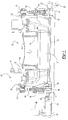
- the hemming machine 20 includes a stationary base 22 which is supported on a ground support surface 23 ( Figure 1).
- a cradle 26 is vertically slidably mounted to the base 22 such that the cradle 26 is vertically movable relative to the base 22.
- a plurality of guide rods 28 are secured to the base 22 and extend through appropriate openings in the cradle 26 to guide the cradle 26 as the cradle 26 vertically moves relative to the base 22.
- the cradle 26 preferably comprises a pair of spaced apart beams 27 having a connected portion 30 at each end of the beams 28.
- the beams 27 are preferably steel I beams with additional cross supports to rigidify the cradle 26.
- a nest 32 is secured to the cradle 26 so that the nest 32 moves in unison with the cradle 26.
- the nest 32 includes an upper surface 34 configured to support a part 36 to be hemmed during the hemming operation.
- the part 36 can comprise, for example, an automotive door panel.
- a pair of ball screws 40 are rotably mounted to the base 22 by thrust bearing assemblies 42 laterally outwardly from opposite sides of the nest 32.
- These ball screws 40 are, in turn, threadably connected to the cradle 26 by an internally threaded nut 44 so that rotation of the ball screws 40 in one direction vertically moves the cradle 26 upwardly relative to the base 22 while, conversely, rotation of the ball screws 40 in the opposite direction moves the cradle 26 vertically downwardly relative to the base 22.
- a drive gear box 46 is associated with each ball screw 40 and positioned underneath its associated ball screw 40.
- Each drive gear box 46 is mechanically connected to its associated ball screw through a gear coupling 48 ( Figure 5) so that output rotation from each drive gear box 46 rotatably drives its associated ball screw 40.
- the gear couplings 48 permit small deflections of its associated ball screw 40 relative to the drive gear box 46 so that a further description thereof is unnecessary.
- an electric drive motor 50 has its output connected through a two speed gear box 52 to one gear box 46.
- An elongated drive shaft 54 then drivingly connects the output from the two speed gearbox 52 to the other gear box 46 such that the gear boxes 46 are rotatably mechanically driven in synchronism with each other by the motor 50 via the gear box 52.
- FIG. 4 a modification of the drive system is there shown in which the drive motor 50 drivingly connects a stub axle 60 through the two-speed gearbox 52.
- the stub axle 60 is, in turn, connected to the input of a bevel gear box 62.
- the bevel gear box 62 includes two output shafts each of which is mechanically connected by a shaft segment 64 to one of the gearboxes 46. Consequently, the bevel gear box 62 ensures that both gearboxes 46 are driven in synchronism with each other.
- a potential advantage of the drive system shown in Figure 4, however, is that any deflection of the drive shafts 64 are evenly distributed between the gearboxes 46.
- a hemming tooling assembly 70 is laterally slidably mounted to the base 22 and typically contains both prehemming tooling 72 as well as final hem tooling 74.
- the hemming tooling 70 is movable between a retracted position, illustrated in Figure 6, and an extended position, illustrated in Figure 6.
- the prehem tooling 72 and final hem tooling 74 In its retracted position ( Figure 6) the prehem tooling 72 and final hem tooling 74 is spaced laterally outwardly from the nest 32 to allow vertical displacement of the nest 32 with its supported part 36 past the tooling 72 and 74.
- the hemming tooling 72 and 74 overlies the nest 32 and thus the part to be hemmed 36.
- Any conventional means, such as a pneumatic or electrical actuator 71 ( Figure 6) can be utilised to move the hemming tooling assemblies 70 between their extended position and retracted position.
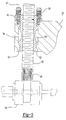
- the nut 44 which threadably mounts the ball screws 40 to the cradle 26 is preferably secured to the cradle 26 by the plurality of spring washers 80, such as Belleville washers and bolts 81. Additionally, a clearance space 82 is provided between the outer surface of the nut 44 and the cradle 26.
- the cradle 26 and bearing 44 are secured together against relative rotation by at least one, and preferably two keys 84. The clearance space between the nut 44 and cradle 26 together with the springs 80 for securing the nut 44 to the cradle thus enables limited lateral deflection of the cradle 26 relative to the ball screws 40.
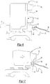
- a pair of downwardly extending pins 90 having a lower tapered portion 92 is secured at each side to both the final hem tooling 74 and prehem tooling 72.
- a pair of sockets 94 in turn is secured to each side of the nest 32 which registers with the lower end of the pin 90 as the nest 32 in moved in preparation for either a final hem or prehem operation as shown in Figure 7. Consequently, upon movement of the nest 32 from the position shown in Figure 7 to the position just prior to the prehem or final hem shown in Figure 8, the tapered head 92 of the pin 90 enters the socket 94 on the nest 32 such that the nest 32 precisely laterally aligns the hemming tooling assembly 70 relative to the nest 32, and thus relative to the part 36.
- the co-operation between the alignment pins 90 and their associated sockets 94 thus ensures that the hemming tooling assembly 70 is precisely aligned to the nest 32 during both the prehem and final hem operations ( Figure 8).
- a control circuit 96 (illustrated only diagrammatically) is associated with the hemming machine 20 to control the activation of the drive motor 50, the operation of the two speed gear box 52, as well as the movement of the hemming tooling assembly 70 between its extended and its retracted position by the actuators 71.
- the control system 96 receives as an input signal the output signal from an absolute shaft encoder 98 which is indicative of the precise rotational position of the ball screws 40 and thus the precise vertical position of the cradle 26 and nest 32.
- the control circuit also receives an input signal from a shaft position encoder 99 associated with the drive motor 50.
- the control system 96 also controls the actuation of a shaft brake 100 operatively coupled with the drive shaft 54 to momentarily lock the drive shaft 54 against rotation as the two speed gear box 52 is actuated between its slow speed and high speed positions.
- the operation of the hemming machine 20 is as follows with reference particularly to Figures 6-13.
- the motor 50 is actuated by the control circuit 96 with the gear box positioned in its high speed position to move the nest 32 to a position beneath the prehem tooling 72.
- the control circuit 96 then actuates the actuator 71 for the hemming tooling assembly 70 to move the hemming tooling assembly 70 so that the prehem tooling 72 overlies the nest 36 as shown in Figure 7.
- the control circuit 96 then actuates the motor 50 to move the cradle 26 and nest 32 to the position shown in Figure 8 just prior to the prehem operation. In doing so, the sockets 94 on the nest 32 engage the tapered pins 90 on the prehemming tooling 72 to precisely align the prehemming tooling 72 relative to the nest 32.
- the control circuit 96 then actuates the brake 100 and then switches the two speed gear box 52 to its low speed high torque position.
- the control circuit 96 then releases the brake 100 and actuates the motor 50 to move the cradle 26 and nest 32 to the position shown in Figure 9 thus performing the prehem operation.
- the hemming tooling 70 is moved to its retracted position as shown in Figure 10 and the control circuit 96 actuates the brake 100 and again switches the gear box 52 to its high speed position.
- the control circuit 96 then actuates the motor 50 to move the cradle 26 and the nest 32 to the position illustrated in phantom line in Figure 10 in which the nest is positioned just below the final hemming tooling 74 and the hemming tooling assembly 70 is moved to its extended position as shown in Figure 11.
- the tapered pins 90 associated with the final hemming tooling 74 co-operate with the sockets 94 on the nest 32 to precisely align the final hemming tooling 74 relative to the nest 32 as the nest 32 is moved to the position shown in Figure 12 just prior to the final hem operation.
- control circuit 96 then actuates the brake 100, switches the two speed gear box 52 to its low speed, and then disengages the brake 100.
- the control system 96 then again activates the drive motor 50 thus driving the nest 32 to the position shown in Figure 13 in which the part 36 is compressed against the final hem tooling 74 thus completing the hem.
- the control system 96 then moves the hemming tooling 70 to is retracted position, the now hemmed part 36 is removed and replaced by a new unhemmed part, and the above process is repeated.
- the use of the two speed gear box 52 mechanically coupled to the output from the drive motor 50 enables the cradle 26 and nest 32 to be rapidly moved between the positions just prior to the prehem and final hem operations in order to minimise cycle time for the hemming machine 20.
- the motor 50 by switching the two-speed gearbox 52 to low speed during the actual prehem and final hem operations, the motor 50 generates sufficient torque to perform the prehem and final hem operations while minimising the power requirements for the drive motor 50.
Landscapes
- Engineering & Computer Science (AREA)
- Mechanical Engineering (AREA)
- Press Drives And Press Lines (AREA)
- Mounting, Exchange, And Manufacturing Of Dies (AREA)
Applications Claiming Priority (2)
| Application Number | Priority Date | Filing Date | Title |
|---|---|---|---|
| US09/861,067 US6474125B1 (en) | 2001-05-18 | 2001-05-18 | Hemming machine with dual ball screw drive |
| US861067 | 2001-05-18 |
Publications (2)
| Publication Number | Publication Date |
|---|---|
| EP1258300A2 true EP1258300A2 (de) | 2002-11-20 |
| EP1258300A3 EP1258300A3 (de) | 2003-10-22 |
Family
ID=25334786
Family Applications (1)
| Application Number | Title | Priority Date | Filing Date |
|---|---|---|---|
| EP02253402A Withdrawn EP1258300A3 (de) | 2001-05-18 | 2002-05-15 | Bördelvorrichtung mit Doppelantriebkugelgewindespindel |
Country Status (4)
| Country | Link |
|---|---|
| US (2) | US6474125B1 (de) |
| EP (1) | EP1258300A3 (de) |
| CA (1) | CA2386827C (de) |
| MX (1) | MXPA02005030A (de) |
Cited By (3)
| Publication number | Priority date | Publication date | Assignee | Title |
|---|---|---|---|---|
| EP1493508A3 (de) * | 2003-07-01 | 2005-01-12 | P.M.C. Tecnologie S.r.l. | Antrieb für eine Vorrichtung zum Krimpen, insbesondere zum Krimpen des Randes eines Kraftfahrzeugfensters |
| KR100604201B1 (ko) | 2005-03-15 | 2006-07-25 | 김경성 | 서보모터를 이용한 클린칭 타입의 헤밍장치 |
| EP2158983A3 (de) * | 2008-09-02 | 2010-03-24 | ThyssenKrupp Drauz Nothelfer GmbH | Verfahren und Vorrichtung zum Beölen einer Falzvorrichtung |
Families Citing this family (20)
| Publication number | Priority date | Publication date | Assignee | Title |
|---|---|---|---|---|
| JP3895538B2 (ja) * | 2000-11-24 | 2007-03-22 | 本田技研工業株式会社 | 縁曲げ加工装置 |
| US6959474B2 (en) * | 2002-08-29 | 2005-11-01 | Campian Jonathon R | Nest and hold station for the joining of sheet materials |
| US7124491B2 (en) * | 2002-12-06 | 2006-10-24 | Tesco Engineering, Inc. | Hemming apparatus and method using a horizontal motion for actuating the die sets |
| US7198068B2 (en) * | 2003-08-28 | 2007-04-03 | Meritor Suspension Systems Co. | Cassette pigtailing machine for a coil spring |
| US7406766B2 (en) * | 2004-10-19 | 2008-08-05 | Bbi Enterprises, L.P. | Apparatus and method for assembling a part for an automotive vehicle |
| US7243518B1 (en) * | 2005-01-21 | 2007-07-17 | Sen-Jung Chuang | Hydraulic cut-off press |
| US7134309B2 (en) * | 2005-02-15 | 2006-11-14 | Tesco Engineering, Inc. | Pre-hemming apparatus |
| WO2007075844A1 (en) | 2005-12-20 | 2007-07-05 | Intuitive Surgical, Inc. | Telescoping insertion axis of a robotic surgical system |
| US7997113B2 (en) | 2007-06-11 | 2011-08-16 | Magna International Inc. | System and method for hemming components |
| US8127423B2 (en) * | 2007-10-05 | 2012-03-06 | Hirotec America, Inc. | Roller hemming system |
| DE102008001969A1 (de) * | 2008-05-26 | 2009-12-03 | Hilti Aktiengesellschaft | Handgeführtes elektrisch betriebenes Eintreibgerät |
| WO2010017171A2 (en) * | 2008-08-04 | 2010-02-11 | Modern Body Engineering | Apparatus and method to cradle and hem panels at an assembly-line station |
| US20110185785A1 (en) * | 2010-02-04 | 2011-08-04 | Eagle Press & Equipment Co. Ltd. | Servo Hemming Press |
| US8276492B1 (en) * | 2009-12-21 | 2012-10-02 | Sen-Jung Chuang | Angle adjustment structure of a hydraulic cut-off press |
| CN102753278B (zh) * | 2010-09-24 | 2015-02-11 | 日产自动车株式会社 | 辊式折边加工系统 |
| CN102430625B (zh) * | 2010-12-17 | 2014-06-25 | 若宇汽车装备工业(昆山)有限公司 | 汽车开启件电控包边单元 |
| US9205479B2 (en) * | 2013-05-30 | 2015-12-08 | Hirotec America, Inc. | Triangular hemming and stamping apparatus |
| CN108526326B (zh) * | 2018-05-31 | 2020-01-10 | 安徽扬子职业技术学院 | 一种汽车模具冲压设备的装夹机构 |
| CN110508697B (zh) * | 2019-09-04 | 2021-06-08 | 中国电子科技集团公司第十四研究所 | 一种汽车覆盖件狭小空间的包边装置及方法 |
| CN112077218B (zh) * | 2020-07-08 | 2022-01-14 | 安徽巨一科技股份有限公司 | 一种基于分段控制原理的高柔性桌式包边机及包边方法 |
Family Cites Families (20)
| Publication number | Priority date | Publication date | Assignee | Title |
|---|---|---|---|---|
| US1288648A (en) * | 1917-05-05 | 1918-12-24 | William Henry Morgan | Flanging-press. |
| US2983159A (en) * | 1960-08-03 | 1961-05-09 | Budd Co | Crosshead column lock |
| US3422658A (en) * | 1967-02-10 | 1969-01-21 | Bliss Co | High velocity forming machine |
| FR2296519A1 (fr) * | 1974-12-30 | 1976-07-30 | Chausson Usines Sa | Dispositif de transfert a deux postes pour machine d'ouvrage |
| US4602497A (en) * | 1984-01-27 | 1986-07-29 | Wallis Bernard J | Die clamping arrangement |
| US4665733A (en) * | 1985-07-18 | 1987-05-19 | Wallis Bernard J | Die clamp |
| JPH0215830A (ja) * | 1988-06-30 | 1990-01-19 | Hirotec:Kk | ヘミング加工装置並びに該装置に用いるリフタ |
| JP2777458B2 (ja) * | 1990-04-24 | 1998-07-16 | 本田技研工業株式会社 | ルーフユニットの製造方法および装置 |
| IT1241375B (it) | 1990-12-27 | 1994-01-10 | Prima Ind Spa | Azionatore lineare a due velocita' con elevata forza di spinta ed elevata velocita' di traslazione per una macchina operatrice, in particolare per una pressa piegatrice. |
| US5150508A (en) * | 1991-06-28 | 1992-09-29 | E. R. St. Denis & Sons, Limited | Hemming machine and method |
| US5454261A (en) | 1993-06-17 | 1995-10-03 | Campian; Jon R. | Hemming machine and method of operation |
| DE4330683C2 (de) * | 1993-09-10 | 1995-07-27 | Audi Ag | Falzvorrichtung |
| US5669296A (en) | 1995-12-04 | 1997-09-23 | Newton; Alan R. | High ratio screw actuated press |
| ES2145651B1 (es) * | 1996-07-26 | 2001-02-16 | Ingemat Sa | Sistema modular de sobremesa para union por pestañado de piezas metalicas. |
| US6154942A (en) * | 1997-09-26 | 2000-12-05 | Tesco Engineering, Inc. | Closure panel hemming apparatus |
| US5930880A (en) * | 1998-02-06 | 1999-08-03 | Tesco Engineering, Inc. | Intensification method and apparatus for hemming machine |
| WO2000030782A1 (es) * | 1998-11-20 | 2000-06-02 | Matrici, S. Coop. | Sistema modular para engatillado y cabezal para su ejecucion |
| US6446478B1 (en) * | 1999-07-29 | 2002-09-10 | Progressive Tool & Industries Co. | Two-stage hemming machine with movable dies |
| US6182492B1 (en) | 1999-11-01 | 2001-02-06 | E.R. St. Denis Inc. | Hemming machine |
| ES2198840T3 (es) | 1999-11-25 | 2004-02-01 | Ford Motor Company | Dispositivo de rebordeado. |
-
2001
- 2001-05-18 US US09/861,067 patent/US6474125B1/en not_active Expired - Lifetime
- 2001-10-24 US US09/999,811 patent/US6612146B2/en not_active Expired - Lifetime
-
2002
- 2002-05-15 EP EP02253402A patent/EP1258300A3/de not_active Withdrawn
- 2002-05-17 MX MXPA02005030A patent/MXPA02005030A/es active IP Right Grant
- 2002-05-17 CA CA002386827A patent/CA2386827C/en not_active Expired - Fee Related
Cited By (3)
| Publication number | Priority date | Publication date | Assignee | Title |
|---|---|---|---|---|
| EP1493508A3 (de) * | 2003-07-01 | 2005-01-12 | P.M.C. Tecnologie S.r.l. | Antrieb für eine Vorrichtung zum Krimpen, insbesondere zum Krimpen des Randes eines Kraftfahrzeugfensters |
| KR100604201B1 (ko) | 2005-03-15 | 2006-07-25 | 김경성 | 서보모터를 이용한 클린칭 타입의 헤밍장치 |
| EP2158983A3 (de) * | 2008-09-02 | 2010-03-24 | ThyssenKrupp Drauz Nothelfer GmbH | Verfahren und Vorrichtung zum Beölen einer Falzvorrichtung |
Also Published As
| Publication number | Publication date |
|---|---|
| US20020170333A1 (en) | 2002-11-21 |
| US6474125B1 (en) | 2002-11-05 |
| EP1258300A3 (de) | 2003-10-22 |
| CA2386827C (en) | 2006-09-12 |
| CA2386827A1 (en) | 2002-11-18 |
| US6612146B2 (en) | 2003-09-02 |
| MXPA02005030A (es) | 2005-09-08 |
| US20020170332A1 (en) | 2002-11-21 |
Similar Documents
| Publication | Publication Date | Title |
|---|---|---|
| US6474125B1 (en) | Hemming machine with dual ball screw drive | |
| US4289441A (en) | Industrial robot | |
| US6644088B1 (en) | Apparatus for flanging metal sheets | |
| CN111872190B (zh) | 一种高精、重载数控折边机 | |
| WO1993016822A1 (de) | Schwenkbiegemaschine | |
| US20020078730A1 (en) | Electric hemming press | |
| CN101279337A (zh) | 大型折弯机双向挠度补偿机构 | |
| KR100604201B1 (ko) | 서보모터를 이용한 클린칭 타입의 헤밍장치 | |
| KR100313722B1 (ko) | 헤밍장치 | |
| US20080041243A1 (en) | Linear motor mounted press machine and press working method | |
| CN110102693A (zh) | 离合器从动盘辅助自动铆钉设备 | |
| EP0427886A1 (de) | Form für ein negatives Eckstück | |
| CN211588285U (zh) | 折弯机直角坐标系机械折弯装置 | |
| US5086638A (en) | Drive mechanism for a hemming apparatus | |
| CN109396241B (zh) | 花键旋压机及其控制方法 | |
| DE102010060627A1 (de) | Umformmaschine mit Stößelregelung | |
| CN220242541U (zh) | 一种纸箱扒边机 | |
| JP2538810B2 (ja) | プレスブレ―キの折曲げ型 | |
| KR100720369B1 (ko) | 산업용 용접 기계장치 | |
| CN219986284U (zh) | 一种便于使用的变电箱打孔装置 | |
| CN222077743U (zh) | 一种双弯角机 | |
| CN119549548B (zh) | 一种用于金属板块加工的整形夹具 | |
| EP0592848A1 (de) | Falzvorrichtung | |
| CN222806919U (zh) | 空压机辅助装配工装及系统 | |
| CN221817272U (zh) | 一种锻压用上料辅助装置 |
Legal Events
| Date | Code | Title | Description |
|---|---|---|---|
| PUAI | Public reference made under article 153(3) epc to a published international application that has entered the european phase |
Free format text: ORIGINAL CODE: 0009012 |
|
| AK | Designated contracting states |
Kind code of ref document: A2 Designated state(s): AT BE CH CY DE DK ES FI FR GB GR IE IT LI LU MC NL PT SE TR |
|
| AX | Request for extension of the european patent |
Free format text: AL;LT;LV;MK;RO;SI |
|
| PUAL | Search report despatched |
Free format text: ORIGINAL CODE: 0009013 |
|
| AK | Designated contracting states |
Kind code of ref document: A3 Designated state(s): AT BE CH CY DE DK ES FI FR GB GR IE IT LI LU MC NL PT SE TR |
|
| AX | Request for extension of the european patent |
Extension state: AL LT LV MK RO SI |
|
| 17P | Request for examination filed |
Effective date: 20040305 |
|
| AKX | Designation fees paid |
Designated state(s): AT BE CH CY DE DK ES FI FR GB GR IE IT LI LU MC NL PT SE TR |
|
| AXX | Extension fees paid |
Extension state: RO Payment date: 20040305 |
|
| 17Q | First examination report despatched |
Effective date: 20050412 |
|
| GRAP | Despatch of communication of intention to grant a patent |
Free format text: ORIGINAL CODE: EPIDOSNIGR1 |
|
| RIN1 | Information on inventor provided before grant (corrected) |
Inventor name: HARRISON, LEE Inventor name: RAFFIN, LOUIS Inventor name: COTE, RAY Inventor name: DENIS, KEITH SAINT |
|
| STAA | Information on the status of an ep patent application or granted ep patent |
Free format text: STATUS: THE APPLICATION IS DEEMED TO BE WITHDRAWN |
|
| 18D | Application deemed to be withdrawn |
Effective date: 20060513 |