EP1258301A2 - Bördelvorrichtung mit mit bewegbaren Matrizenkasetten - Google Patents
Bördelvorrichtung mit mit bewegbaren Matrizenkasetten Download PDFInfo
- Publication number
- EP1258301A2 EP1258301A2 EP02253408A EP02253408A EP1258301A2 EP 1258301 A2 EP1258301 A2 EP 1258301A2 EP 02253408 A EP02253408 A EP 02253408A EP 02253408 A EP02253408 A EP 02253408A EP 1258301 A2 EP1258301 A2 EP 1258301A2
- Authority
- EP
- European Patent Office
- Prior art keywords
- nest
- die
- hemming
- cartridge
- base
- Prior art date
- Legal status (The legal status is an assumption and is not a legal conclusion. Google has not performed a legal analysis and makes no representation as to the accuracy of the status listed.)
- Withdrawn
Links
Images




Classifications
-
- B—PERFORMING OPERATIONS; TRANSPORTING
- B21—MECHANICAL METAL-WORKING WITHOUT ESSENTIALLY REMOVING MATERIAL; PUNCHING METAL
- B21D—WORKING OR PROCESSING OF SHEET METAL OR METAL TUBES, RODS OR PROFILES WITHOUT ESSENTIALLY REMOVING MATERIAL; PUNCHING METAL
- B21D39/00—Application of procedures in order to connect objects or parts, e.g. coating with sheet metal otherwise than by plating; Tube expanders
- B21D39/02—Application of procedures in order to connect objects or parts, e.g. coating with sheet metal otherwise than by plating; Tube expanders of sheet metal by folding, e.g. connecting edges of a sheet to form a cylinder
- B21D39/021—Application of procedures in order to connect objects or parts, e.g. coating with sheet metal otherwise than by plating; Tube expanders of sheet metal by folding, e.g. connecting edges of a sheet to form a cylinder for panels, e.g. vehicle doors
Definitions
- the present invention relates generally to sheet metal hemming machines.
- sheet metal hemming machines there are many previously known hemming machines. Many industries, such as the automotive industry, utilize sheet metal hemming machines to secure two sheet metal parts together. These sheet metal hemming machines typically comprise a base having a nest vertically slidably mounted relative to the base. The nest, in turn, supports the part to be hemmed.
- At least one and typically three to five hemming die sets are laterally slidably mounted to the base and movable between an extended position and a retracted position. In the extended position, the die set overlaps the nest so that vertical displacement of the nest towards the hemming die causes the part to be hemmed to be compressed upon the die thus forming the hem.
- a prehem is first performed by a prehem die to bend the sheet metal at an angle of approximately 45° while a final hem die retrorsely flattens the sheet metal hem together.
- the part to be hemmed is first positioned on the nest and, with the hemming dies retracted, the nest is moved to a position just below the prehem die and clearing the part flange to be hemmed.
- the prehem die is then moved to an extended position after which the nest is displaced vertically upwardly against the prehem die and retracted after having reached the nominal hemming pressure.
- the hemming dies are then moved to a retracted position and the nest is moved to a position just below the final hem die.
- the final hem die is then moved to an extended position and the nest is vertically displaced against the final hem die to complete the hem.
- the dies are then moved to their retracted position after retraction of the nest once reaching the final hem pressure and the part is removed from the nest and replaced by a new unhemmed part.
- a still further disadvantage of these previously known hemming machines is that periodic maintenance, repair and the like of the hemming machine is oftentimes required. Furthermore, such maintenance and/or repair typically involves the hemming tooling or die sets that are mounted to the base. When such maintenance and/or repair of the hemming tooling is required, it is necessary to shut down the operation of the entire hemming machine. This, in turn, disadvantageously results in work stoppages or slowdown for the assembly line.
- the present invention provides a hemming machine which overcomes all of the above-mentioned disadvantages of the previously known hemming machines.
- the hemming machine comprises a stationary base mounted on a ground support surface.
- the base has a work station at which the parts to be hemmed are processed.
- a lifting beam is vertically slidably mounted to the base at the work station so that the lifting beam is movable between a raised position and a lowered position.
- ball screws are utilized to mount the lifting beam to the base while an electric motor is drivingly connected to the ball screws to effect the vertical movement of the lifting beam.
- An aspect of present invention further comprises two die cartridges, each of which are substantially rectangular in shape, having a central through opening.
- the hemming tooling or die sets are mounted to the die cartridges and preferably to the upper surface of the die cartridges so that the hemming tooling or die sets move in unison with the die cartridge.
- Each die cartridge furthermore, includes a nest vertically mounted within its respective through opening.
- the die cartridges as well as their associated nests may be designed to process the same part or, alternatively, may contain different hemming tooling and different nests to accommodate different parts.
- a conveyor assembly is provided for laterally movably mounting the die cartridges relative to the base such that each die cartridge with its associated nest is movable between a first position in which the die cartridge and its associated nest are positioned in alignment with the work station, and a second position in which the die cartridge and its associated nest are laterally spaced from the work station.
- Any conventional means such as a chain or belt drive, may be utilized to move the die cartridges with their associated nests between the first and second positions.
- the main ball screw servo-motor With one die cartridge with its associated nest positioned at the first position, i.e. in alignment with the work station, the main ball screw servo-motor is actuated thus lifting the lifting beam into engagement with the nest. Thereafter, a first clamp assembly is actuated to secure the lifting beam and nest together so that the lifting beam and nest vertically move in unison with each other.
- two or more alignment pins are provided on either the nest or the lifting beam which engage alignment holes formed in the other of the nest or lifting beam.
- the nest and die cartridge secured to it through four horizontal locking pins are lowered by the lifting beam until the die cartridge rests upon a support surface on the base. Thereafter, a second clamp assembly is actuated in order to firmly, but releasably, clamp the die cartridge to the base.
- the nest clamped to the lifting beam by the first and second clamp assemblies and the four horizontal locking pins disengaged in between the nest and die cartridge vertical displacement of the lifting beam vertically moves the nest relative to the die cartridge in order to perform the hemming operation.
- the hemming operation itself is conventional, i.e. first a prehem is formed on the part and then a final hem is performed on the part. Following completion of the hemming operation, the hemmed part is removed and replaced by an unhemmed part which is then hemmed in the conventional fashion.
- the die cartridge at the work station with its associated nest are laterally moved away from the work station to their second position. Thereafter, the other die cartridge with its associated nest is moved from its second position to its first position, i.e. in alignment with the work station, and the above process is repeated.
- An advantage of the primary advantage of the hemming machine of this aspect of the present invention is that the hemming machine may be utilized to continuously hem parts even though maintenance and/or repair of the hemming tooling is required.
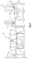
- FIG. 1 a perspective view of a hemming machine 20 having a base 22 supported on a ground surface is shown.
- the base 22 further includes a work station 24 at which the parts to be hemmed are positioned.
- a lifting beam 26 is positioned at the work station 24 and is vertically movably mounted to the base 22 by a pair of spaced apart ball screws 28 which, in turn, are rotatably mounted with respect to the base 22 by thrust bearings 29.
- the lifting beam 26, furthermore, preferably comprises a pair of spaced apart beams 30 which are secured together at each end.
- a motor 32 preferably an electric servo-motor, is drivingly connected to each ball screw 28 through gear box 34 and a connecting shaft 35 (Figure 16).
- an auxiliary motor 36 is also selectively drivingly connected to the ball screws 28 through a gear box 38 and clutch 40 in a fashion to be subsequently described in greater detail.
- a first frame 50 is supported on the ground support surface at a position laterally spaced from the work station 24 while, similarly, a second frame 52 is also supported on the ground support surface on the opposite lateral side of the work station 24.
- a conveyor system 54 extends not only along an upper surface of both frames 50 and 52, but also across the work station 24.
- the conveyor assembly 54 includes a pair of spaced apart conveyor rails 56. Furthermore, each conveyor rail 56 includes stationary sections 58 which are mounted to an upper surface of the frames 50 and 52. The conveyor rails 56 further include a lifting beam section 62 which is mounted to the lifting beam 26. Each conveyor rail 56 also includes two laterally movable sections 64 between the stationary sections 58 on the frames 50 and 52, and the lifting beam rail section 62.
- the hemming machine 20 further comprises two die cartridges 70 and 72 which are generally rectangular in shape and each having a through opening 74 ( Figure 2). Both die sets 70 and 72 have a lower surface supported by the conveyors 54 so that the die cartridges 70 and 72 are laterally movable between a first position in which the die cartridge 72 is aligned with the work station 24, and a second position, illustrated in Figures 1 and 2, in which the die cartridges 72 are laterally spaced outwardly from the work station 24 and positioned above their respective frames 50 and 52.
- Each die cartridge 70 and 72 includes hemming tooling 76 and 78, respectively.
- the hemming tooling 76 and 78 is preferably secured to an upper surface of the die cartridges 70 and 72, respectively, although the hemming tooling 76 and 78 may be secured to their respective die cartridges 70 and 72 in any conventional fashion so that the hemming tooling 76 and 78 move in unison with their respective die cartridges 70 and 72.
- the hemming tooling 76 and 78 may be symmetrical to each other for processing or hemming the left hand and right hand of the same type of part, or may be completely different from each other for processing or hemming different parts.
- the hemming tooling 76 and 78 is conventional in construction.
- the hemming tooling 76 and 78 each include hemming dies which are laterally movable relative to their respective die cartridges 70 and 72 to perform both a prehem and final hem operation in the fashion that will subsequently be described in greater detail.
- a nest 80 is disposed within the through opening 74 of the die cartridge 70 while, similarly, a nest 82 is disposed within the through opening 74 of the second die cartridge 72.
- the nests 80 and 82 are adapted to support the part to be hemmed at their upper surface.
- the nests 80 and 82 are vertically movably mounted relative to their die cartridges 70 and 72, respectively, during the hemming operation.
- the hemming machine is there shown with the die cartridge 72 in its second position, i.e. spaced laterally outwardly from the work station 24.
- the lifting beam 26 is in a lower position such that the rail section 62 mounted to the lifting beam 26 is positioned below the rail sections 54 and 64.
- two or more horizontal locking pins 86 mounted to the die cartridge 72 engage the nest 82 to thereby secure the nest 82 to the die cartridge 72.
- the horizontal locking pins 86 support the nest 82 relative to the die cartridge 72 so that a bottom surface 88 of the nest 82 is positioned upwardly of and spaced from the conveyor rails 56. In doing so, the conveyor rails 56 support only the die cartridge 72 for lateral movement along the frame 52.
- the main servo-motor 32 ( Figure 1) is actuated to rotatably drive the ball screws 28 to move the lifting beam 26 to a position in which the lifting beam rail section 62 is aligned with the rail sections 58 and 64. At this time, the die cartridge 72 is still positioned in its second position and thus supported by the frame 52 and all conveyors are aligned.
- the die cartridge 72 with its supported nest 82 is driven along the conveyor rail sections 58, 64 and 62 until the die cartridge 72 is positioned in its first position, i.e. in alignment with the work station 24 as depicted in Figure 5.
- Any conventional means such as a drive motor 90 and drive chain or belt 92 ( Figures 1 and 5), may be utilized to longitudinally displace the die cartridge 72 with its supported nest 82 between its first and second positions.
- a ball screw, piston and cylinder and/or the like may be used to drive the die cartridge along the rail sections 58, 64 and 62.
- the main servo-motor 32 ( Figure 1) is again actuated thus lifting the lifting beam 26 so that the lifting beam 26 engages the nest 82 and elevates both the nest 82 with its attached die cartridge 72. In doing so, the die cartridge 72 is elevated above the moveable conveyor rail sections 64.
- Figure 6a the die cartridge 72 is elevated above the movable rail segment 64 thus removing the weight of the die cartridge 72 and nest 82 from the moveable rail segment 64.
- an actuator 66 ( Figure 6a), which may be of any conventional construction such as a pneumatic actuator, laterally displaces the movable rail segment 64 laterally outwardly such that the rail segments 64 register with channels 100 formed in the die cartridge 72. Consequently, upon subsequent lowering of the die cartridge 72, the moveable rail sections 64 nest within the die cartridge channels 100 as shown in Figure 6b.
- At least two alignment pins 102 are preferably secured to the lifting beam 26. These alignment pins 102 register with and engage alignment openings 104 (only one illustrated in Figure 7) located in the nest 82 to ensure proper alignment of the nest 82 and lifting beam 26. Alternatively, of course, the alignment pins 102 can be secured to the nest 82 while the alignment holes 104 are formed in the lifting beam 26.
- a pair of clamps 106 ( Figure 7) are actuated to firmly secure the nest 82 to the lifting beam 26.
- the clamps 106 may be of any conventional construction, but preferably comprise a pair of hooks pivotally mounted to the lifting beam 26 and movable between a clamped position and a release position by pneumatic actuators.
- the lifting beam 26 is lowered to the position illustrated in Figure 8 in which the bottom of the die cartridge 72 is supported on an upper surface of the base 22.
- a clamp assembly 110 ( Figures 1 and 10) is then actuated from an unclamped and to a clamped position in order to firmly clamp the die cartridge 72 against vertical movement to the base 22.
- the clamp assembly 110 preferably comprises four hooks 112 (only one shown in Figures 1 and 10) with each hook positioned at each corner of the die cartridge 72.
- the hook 112 is movable between an unclamped position, illustrated in phantom line in Figure 11, and a clamped position, illustrated in solid line in Figure 11.
- the hook 112 is pivotally mounted by a bearing assembly 114 to the base 22 and, in its clamped position (solid line), engages a catch 116 formed on the die cartridge 72.
- Any conventional means such as a pneumatic actuator 118, is used to pivot the hook 112 between its clamped and unclamped position.
- the bearing assembly 114 preferably engages an eccentric member 120 rotatably mounted between the hook 112 and the pivot shaft 122 secured to the base 22. This eccentric member 120 increases the downward force of the hook 112 against the catch 116 thereby firmly, but releasably, locking the die cartridge 72 against vertical movement relative to the base 22.
- the actuators 86 which secure the die cartridge 72 to the nest 82 are moved to their retracted or release position thus freeing the nest 82 for vertical movement relative to the die cartridge 72. Furthermore, at this time, the hemming machine 20 is ready to perform hemming operations.
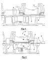
- the hemming tooling is laterally movably mounted to the die cartridge 72 between a position in which the hemming tooling 78 is spaced laterally outwardly from the nest 82, as shown in Figure 12, and a position in which the hemming tooling 78 overlies both the nest 82 as well as the part 130 to be hemmed.
- Any conventional means may be utilized to laterally displace the hemming tooling 78 on the die cartridge 72.
- the hemming tooling 78 includes both prehem tooling 132 as well as final hemming tooling 134.
- the hemming tooling 78 is moved to its retracted position and the nest 82 is moved from its prehem position, illustrated in solid line in Figure 12, and its final hem position, illustrated in phantom line in Figure 12.
- the hemming tooling 78 is moved so that the final hemming tooling 134 overlies the prehem.
- the main servo-motor 32 ( Figure 1) is actuated to move the nest 82 so that the part 130 to be hemmed is positioned just below the final hemming tooling 134.
- the nest 82 is then elevated to the position shown in Figure 15 in which the part 130 to be hemmed is compressed against the final hemming die 134 thus completing the hem.
- the nest 82 is thereafter lowered, the hemming tooling 78 retracted to its lateral outer position and the now hemmed part 130 is removed from the nest 82 and replaced by new parts to be hemmed.
- the clutch 40 is engaged and the auxiliary motor 36 is actuated only during the final phase of hemming operations, i.e. only when the part 130 is compressed against the hemming tools 132 or 134.
- the gearbox 38 also multiplies the torque output from the auxiliary motor 36 thereby generating sufficiently high torque to form the hem.
- the above-identified process for moving and clamping both the die cartridge and nest within the work station is simply reversed.
- the die cartridge 72 is moved to a second position, i.e. spaced laterally outwardly from the work station 24, the other die cartridge 72 is moved into the work station 24 and secured in place in the previously described fashion for the die cartridge 72 with its nest 82.
- any required maintenance and/or repair of the die cartridge 72, its nest 82 or tooling 78 may be performed while the hemming machine 20 hems parts using the other die cartridge 70 and its associated nest 80 and tooling 76.
Landscapes
- Engineering & Computer Science (AREA)
- Mechanical Engineering (AREA)
- Mounting, Exchange, And Manufacturing Of Dies (AREA)
Applications Claiming Priority (4)
| Application Number | Priority Date | Filing Date | Title |
|---|---|---|---|
| US09/861,067 US6474125B1 (en) | 2001-05-18 | 2001-05-18 | Hemming machine with dual ball screw drive |
| US861067 | 2001-05-18 | ||
| US09/999,811 US6612146B2 (en) | 2001-05-18 | 2001-10-24 | Hemming machine with movable die cartridges |
| US999881 | 2001-10-24 |
Publications (2)
| Publication Number | Publication Date |
|---|---|
| EP1258301A2 true EP1258301A2 (de) | 2002-11-20 |
| EP1258301A3 EP1258301A3 (de) | 2003-10-22 |
Family
ID=27127602
Family Applications (1)
| Application Number | Title | Priority Date | Filing Date |
|---|---|---|---|
| EP02253408A Withdrawn EP1258301A3 (de) | 2001-05-18 | 2002-05-15 | Bördelvorrichtung mit mit bewegbaren Matrizenkasetten |
Country Status (3)
| Country | Link |
|---|---|
| EP (1) | EP1258301A3 (de) |
| CA (1) | CA2387033C (de) |
| MX (1) | MXPA02005028A (de) |
Cited By (3)
| Publication number | Priority date | Publication date | Assignee | Title |
|---|---|---|---|---|
| CN105522069A (zh) * | 2016-01-14 | 2016-04-27 | 东莞市凯安机械配件有限公司 | 一种折叠散热片的全自动加工设备 |
| CN113399568A (zh) * | 2021-06-25 | 2021-09-17 | 长春一汽富维汽车零部件股份有限公司 | 一种车轮滚型模具换模的工装线和方法 |
| WO2022007363A3 (zh) * | 2020-07-08 | 2022-11-24 | 安徽巨一科技股份有限公司 | 一种基于分段控制原理的高柔性桌式包边机及包边方法 |
Family Cites Families (2)
| Publication number | Priority date | Publication date | Assignee | Title |
|---|---|---|---|---|
| US5454261A (en) * | 1993-06-17 | 1995-10-03 | Campian; Jon R. | Hemming machine and method of operation |
| US6182492B1 (en) * | 1999-11-01 | 2001-02-06 | E.R. St. Denis Inc. | Hemming machine |
-
2002
- 2002-05-15 EP EP02253408A patent/EP1258301A3/de not_active Withdrawn
- 2002-05-17 CA CA 2387033 patent/CA2387033C/en not_active Expired - Fee Related
- 2002-05-17 MX MXPA02005028 patent/MXPA02005028A/es active IP Right Grant
Cited By (4)
| Publication number | Priority date | Publication date | Assignee | Title |
|---|---|---|---|---|
| CN105522069A (zh) * | 2016-01-14 | 2016-04-27 | 东莞市凯安机械配件有限公司 | 一种折叠散热片的全自动加工设备 |
| WO2022007363A3 (zh) * | 2020-07-08 | 2022-11-24 | 安徽巨一科技股份有限公司 | 一种基于分段控制原理的高柔性桌式包边机及包边方法 |
| EP4112202A4 (de) * | 2020-07-08 | 2024-05-15 | Jee Technology Co., Ltd. | Hochflexible tischfalzmaschine nach dem prinzip der segmentierten steuerung und falzverfahren |
| CN113399568A (zh) * | 2021-06-25 | 2021-09-17 | 长春一汽富维汽车零部件股份有限公司 | 一种车轮滚型模具换模的工装线和方法 |
Also Published As
| Publication number | Publication date |
|---|---|
| EP1258301A3 (de) | 2003-10-22 |
| MXPA02005028A (es) | 2005-09-08 |
| CA2387033A1 (en) | 2002-11-18 |
| CA2387033C (en) | 2006-08-08 |
Similar Documents
| Publication | Publication Date | Title |
|---|---|---|
| US6612146B2 (en) | Hemming machine with movable die cartridges | |
| US11478834B2 (en) | Processing planar workpieces | |
| CN107414493A (zh) | 自动压接设备 | |
| WO2016117896A1 (ko) | 다기능 절곡 장치 | |
| CN116867621B (zh) | 用于加工板状工件的机床的再调整装置及用于再调整板状工件以在机床中进行加工的方法 | |
| CN113618285B (zh) | 一种升降式纵缝焊接设备 | |
| CN1073971C (zh) | 弯玻璃板传递机 | |
| CN116871366B (zh) | 折弯机用送料装置及使用方法 | |
| CN208391686U (zh) | 无心磨床悬臂机械手装置 | |
| CN214212698U (zh) | 一种焊接定位平台 | |
| EP1258301A2 (de) | Bördelvorrichtung mit mit bewegbaren Matrizenkasetten | |
| CN115519026B (zh) | 一种用于加工铝模板的冲孔装置 | |
| CN113953551B (zh) | 一种全自动钻孔机 | |
| CN110802407A (zh) | 一种用于飞机轮毂装配线的轮毂夹具及其应用方法 | |
| CZ296492B6 (cs) | Modulární stolní systém pro spojování kovových cástí obrubováním | |
| US6314783B1 (en) | Electromechanical hemming apparatus and method | |
| CN213915815U (zh) | 应用在冲压生产中的柔性拾取自动上下料机构 | |
| JP2003311337A (ja) | 曲げ加工装置 | |
| CN222370026U (zh) | 一种防脱落的钣金折弯设备 | |
| CN121199448B (zh) | 一种钢箱梁焊接工装及焊接工艺 | |
| CN221538150U (zh) | 一种法兰生产用法兰钻孔装置 | |
| RU2809881C1 (ru) | Гибочный станок | |
| KR101462921B1 (ko) | 스트레치 벤딩 금형 교환장치 | |
| CN213798284U (zh) | 一种开式可倾压力机 | |
| CN114798923B (zh) | 一种板材生产用冲压模具及其使用方法 |
Legal Events
| Date | Code | Title | Description |
|---|---|---|---|
| PUAI | Public reference made under article 153(3) epc to a published international application that has entered the european phase |
Free format text: ORIGINAL CODE: 0009012 |
|
| AK | Designated contracting states |
Kind code of ref document: A2 Designated state(s): AT BE CH CY DE DK ES FI FR GB GR IE IT LI LU MC NL PT SE TR |
|
| AX | Request for extension of the european patent |
Free format text: AL;LT;LV;MK;RO;SI |
|
| PUAL | Search report despatched |
Free format text: ORIGINAL CODE: 0009013 |
|
| AK | Designated contracting states |
Kind code of ref document: A3 Designated state(s): AT BE CH CY DE DK ES FI FR GB GR IE IT LI LU MC NL PT SE TR |
|
| AX | Request for extension of the european patent |
Extension state: AL LT LV MK RO SI |
|
| 17P | Request for examination filed |
Effective date: 20040305 |
|
| AKX | Designation fees paid |
Designated state(s): AT BE CH CY DE DK ES FI FR GB GR IE IT LI LU MC NL PT SE TR |
|
| AXX | Extension fees paid |
Extension state: RO Payment date: 20040305 |
|
| GRAP | Despatch of communication of intention to grant a patent |
Free format text: ORIGINAL CODE: EPIDOSNIGR1 |
|
| RIN1 | Information on inventor provided before grant (corrected) |
Inventor name: HARRISON, LEE Inventor name: RAFFIN, LOUIS Inventor name: COTE, RAY Inventor name: DENIS, KEITH SAINT |
|
| STAA | Information on the status of an ep patent application or granted ep patent |
Free format text: STATUS: THE APPLICATION IS DEEMED TO BE WITHDRAWN |
|
| 18D | Application deemed to be withdrawn |
Effective date: 20060425 |