EP1258320A2 - Perceuse-fraiseuse pour appliquer des éléments métalliques à des pièces de meuble - Google Patents
Perceuse-fraiseuse pour appliquer des éléments métalliques à des pièces de meuble Download PDFInfo
- Publication number
- EP1258320A2 EP1258320A2 EP02008821A EP02008821A EP1258320A2 EP 1258320 A2 EP1258320 A2 EP 1258320A2 EP 02008821 A EP02008821 A EP 02008821A EP 02008821 A EP02008821 A EP 02008821A EP 1258320 A2 EP1258320 A2 EP 1258320A2
- Authority
- EP
- European Patent Office
- Prior art keywords
- workpiece
- suction cup
- machine
- driving
- cup assembly
- Prior art date
- Legal status (The legal status is an assumption and is not a legal conclusion. Google has not performed a legal analysis and makes no representation as to the accuracy of the status listed.)
- Granted
Links
Images



Classifications
-
- B—PERFORMING OPERATIONS; TRANSPORTING
- B27—WORKING OR PRESERVING WOOD OR SIMILAR MATERIAL; NAILING OR STAPLING MACHINES IN GENERAL
- B27F—DOVETAILED WORK; TENONS; SLOTTING MACHINES FOR WOOD OR SIMILAR MATERIAL; NAILING OR STAPLING MACHINES
- B27F5/00—Slotted or mortised work
- B27F5/02—Slotting or mortising machines tools therefor
- B27F5/12—Slotting or mortising machines tools therefor for making holes designed for taking up fittings, e.g. in frames of doors, windows, furniture
-
- B—PERFORMING OPERATIONS; TRANSPORTING
- B25—HAND TOOLS; PORTABLE POWER-DRIVEN TOOLS; MANIPULATORS
- B25B—TOOLS OR BENCH DEVICES NOT OTHERWISE PROVIDED FOR, FOR FASTENING, CONNECTING, DISENGAGING, OR HOLDING
- B25B11/00—Work holders not covered by any preceding group in the subclass, e.g. magnetic work holders, vacuum work holders
- B25B11/005—Vacuum work holders
-
- B—PERFORMING OPERATIONS; TRANSPORTING
- B27—WORKING OR PRESERVING WOOD OR SIMILAR MATERIAL; NAILING OR STAPLING MACHINES IN GENERAL
- B27M—WORKING OF WOOD NOT PROVIDED FOR IN SUBCLASSES B27B - B27L; MANUFACTURE OF SPECIFIC WOODEN ARTICLES
- B27M1/00—Working of wood not provided for in subclasses B27B - B27L, e.g. by stretching
- B27M1/08—Working of wood not provided for in subclasses B27B - B27L, e.g. by stretching by multi-step processes
Definitions
- the present invention relates to a drilling and milling machine, which has been specifically designed for applying metal elements or fixtures to furniture pieces.
- furniture pieces conventionally comprise panels having a parallelepiped configuration, which panel, in order to make a finished furniture article, must be subjected to a plurality of drilling and/or milling operations, as suitably spaced from one another.
- Some or all of the thus made holes or milled portions are provided for receiving metal elements or fixtures, usually comprising metal inserts such as ring nuts, coupling elements, hinges and so on, to allow an individual panel to be coupled to other panels for forming a furniture article, an equipped wall or other construction.
- each panel is engaged by gripping means on a side edge thereof, and is driven along a supporting and handling device, usually including a roller assembly.
- a drawback of the gripper driving and locating system is that the grippers would occupy regions of the panel which could be affected by the drilling or milling operations, thereby rendering the panel assembling a rather difficult operation.
- the aim of the present invention is to provide such a drilling and milling machine, for making furniture articles, which comprises a panel driving system specifically designed for overcoming the above mentioned drawback of prior drilling and milling machines.
- a main object of the present invention is to provide such a drilling and milling machine including a workpiece driving system, designed for driving the workpieces or panels so as to leave the edges of the panels substantially free in order not to hinder further panel processing operations.
- Another object of the present invention is to provide such a drilling and milling machine including a workpiece or panel driving system allowing the individual panels to be accurately located, without damaging said panels.
- a drilling and milling machine specifically designed for applying metal elements or fixtures to furniture pieces
- said machine comprising supporting means for supporting a workpiece by an operating head in a working station, driving means for driving said workpiece through said supporting means, from at least a supplying position to the working station and from the working position to an unloading position, and clamping means for clamping said workpiece in said working station, characterized in that said driving means comprise suction cup means designed for affecting only a surface of the workpiece, while leaving the perimetrical edges and top edge of said work piece substantially free.
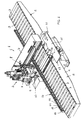
- the drilling and milling machine which has been generally indicated by the reference number 1, comprises a supporting device, designed for supporting one or more panels or workpieces to be processed, said supporting device comprising roller assemblies 2 including a plurality of idle rollers 3, coupled to a supporting framework 4.
- the supporting device is adapted to support a workpiece, not shown, which typically comprises a panel to which metal elements or fixtures must be applied by an operating head 5 which can be displaced on a cross guide 6 traversing the top of the supporting device.
- the operating head 5 comprises, in a per se known manner, a tool exchanging device 7, a screwing on and off device 8, an insert supplying device 9 for supplying insert elements, not specifically shown, to be applied to the workpiece.
- the subject machine On a working bench 10, in a working position of the operating head 5, the subject machine further comprises a clamping device 11 for clamping the workpiece to be processed.
- Said clamping device 11 comprises an aligning element, arranged in front of the bench 10, on the other side of the workpiece supporting device, and comprises moreover a plate 12 including a plurality of transversally movable vertical axis rollers 13, which can be driven in the longitudinal direction of the supporting device 2, so as to clamp the workpiece in its working position, as counterurged by guiding rollers 14 and 15 of a translating device 16.
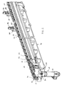
- the translating or deriving device 16 is designed for driving the workpiece on the roller assemblies, or transport device 2, and comprises a longitudinally extending guide 17 which extends along a side of the transport device and comprises guide rollers, respectively 14 having a vertical axis and 15 having a horizontal axis, adapted to respectively engage the outer edge and bottom edge of the workpiece.
- the longitudinal guide 17 slidably supports a floating suction cup device 18, designed for sliding along the guide 17 and for clamping the workpiece to drive it, along the roller assemblies, to a set working position, and being furthermore designed for unloading said workpiece.
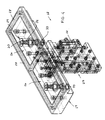
- the floating suction cup device 18 which is shown in a more detailed manner in figures 3-6, comprises a suction cup assembly 19, supported by a slide 20 which can be slidably driven along the mentioned longitudinal guide 17.
- the driving of the slide 20 and, accordingly, of the suction cup assembly 19 along the guide 17 is controlled by a motor-reducing unit 21, driving a belt coupled to said slide 20.
- the suction cup assembly 19 is supported by said slide 20 through a guide carriage 23, so as to be vertically displaced with respect to said slide, as controlled by a pneumatic piston 22.
- the vertical displacement of the suction cup assembly 19 allows the suction cups included therein to be moved toward the bottom surface of the piece.
- the suction cup assembly is coupled to the vertical guide carriage 23 through a horizontal guide 24 designed for allowing the suction cup assembly to be horizontally and transversely driven with respect to the workpiece longitudinal driving direction.
- the suction cup assembly is centered by a pair of spring urged pusher elements 25, which essentially comprise a small plunger operating against a coaxial coil spring, said pusher elements being adapted to hold at a centered position said suction cup assembly, while allowing, owing to the elastic properties of the spring, a slight cross displacement, in both directions with respect to the middle longitudinal line, in order to compensate for possible workpiece unevennesses, due, for example, to a non perfectly rectilinear edge thereof.
- the suction cup assembly 19 comprises, in this embodiment, two suction cups 26, but, as it should be apparent to one skilled in the art, it could be also comprise a single suction cup or three or more suction cups, depending on requirements.
- the suction cup assembly 19 comprises a double tray construction 27, designed for defining two recesses and comprising an edge 32 including a gasket 28 made of rubber or any other suitable resilient materials.
- a ball shutter element 29 is provided, said ball shutter element comprising a ball 30 adapted to obstruct a hole, as said ball is urged by an urging spring 31.
- the shutter element 29, as shown, is coupled to a suction source, or vacuum source through suitable ducts 33 thereby, as a panel is contacted by the suction cup assembly, the lower surface of said panel will be caused to bear on said gasket 28, thereby deforming it so as to contact the ball 30 which will be downward driven, thereby partially freeing the hole and providing a negative pressure in the cavity of the suction cup 26.
- said workpiece or panel Upon having processed the workpiece and having removed it from the working station, said workpiece or panel will be disengaged by lowering the suction cup assembly 19, by a control piston 22.
- the suction cup assembly 19 is adapted to engage a workpiece and drive it, along the roller assemblies, to the working or processing bench.
- the suction cup assembly will drive the workpiece rightward with reference to figure 1, to the following unloading position thereof.
- said suction cup assembly 19 comprises a double chamber, so as to allow the individual suction cups 26 thereof to be supplied in a mutual independent manner.
- the operating speed and accelerations, as the workpiece is driven, are suitable adjusted to allow an accurate locating of the workpiece to a set working position, and in order to prevent the workpiece from being damaged.
- the workpiece driving adjusting is performed by a driving control system, comprises a cam assembly or set 34, controlling three microswitches.
- a first microswitch reduces the workpiece feeding speed
- a second microswitch controls the assembly so as to be properly located at a starting position thereof
- a third microswitch operates as a safety control element, i.e. a limit switch, operating to stop the assembly in the case in which limit positions would be exceeded.
- the driving control system comprises moreover a pair of wheel pusher elements 35, designed for operating on the top surface of the work piece to hold it in its working position, in cooperation with a second pair of pusher wheel elements 36 of the plate aligner 12.
- Each said pusher element 35 comprises a pair of photocells 37 and 38 provided for respectively detecting the inlet and outlet of the workpiece edge, in order to control the operation of the pusher elements.
- the workpiece typically a wood or other material panel used for making furniture articles
- the workpiece is caused to slide along said roller assemblies from a supplying or feeding position, at the left with reference to figure 1, to a working position at the operating head 5, by operating the suction cup assembly 19.
- the latter affects only the bottom surface of the panel while leaving the side edges and top edge of the panel free.
- the suction cup assembly 19 is raised and brought to contact the panel bottom surface, thereby automatically providing a negative pressure, through the above disclosed ball shutter elements.
- the panel is brought to its working position, where on the panel are performed all the necessary processing operations, which are performed by the mentioned operating head.
- the panel is driven by the suction cup assembly along the roller assembly, rightward with reference to figure 1, to an unloading position or a following processing station.
- the machine according to the present invention provides, owing to the provision of the disclosed suction cup assembly, great advantages, since the perimetrical edges of the panel are left fully free, thereby preventing the panel from hindering further processing operations.
- a further advantage of the machine according to the invention is that, owing to the specifically designed suction cup assembly, it is possible to accurately drive the panel without damaging it, owing to the self-centering characteristics and self-adjusting properties of the assembly during the driving thereof.
- the subject drilling and milling machine allows to easily apply metal elements and fixtures to the panels for forming the furniture pieces, in a manner which does not damage the panels or obstruct the processing steps.
- the used materials as well as the contigent size and shapes, can be any, depending on requirements and the status of the art.
Landscapes
- Engineering & Computer Science (AREA)
- Life Sciences & Earth Sciences (AREA)
- Mechanical Engineering (AREA)
- Wood Science & Technology (AREA)
- Forests & Forestry (AREA)
- Milling, Drilling, And Turning Of Wood (AREA)
- Perforating, Stamping-Out Or Severing By Means Other Than Cutting (AREA)
Applications Claiming Priority (2)
| Application Number | Priority Date | Filing Date | Title |
|---|---|---|---|
| IT2001MI001032A ITMI20011032A1 (it) | 2001-05-17 | 2001-05-17 | Macchina foratrice e fresatrice particolarmente studiata per l'applicazione di ferramenta ed elementi di mobili |
| ITMI20011032 | 2001-05-17 |
Publications (3)
| Publication Number | Publication Date |
|---|---|
| EP1258320A2 true EP1258320A2 (fr) | 2002-11-20 |
| EP1258320A3 EP1258320A3 (fr) | 2006-07-19 |
| EP1258320B1 EP1258320B1 (fr) | 2008-08-20 |
Family
ID=11447690
Family Applications (1)
| Application Number | Title | Priority Date | Filing Date |
|---|---|---|---|
| EP02008821A Expired - Lifetime EP1258320B1 (fr) | 2001-05-17 | 2002-04-19 | Perceuse-fraiseuse pour appliquer des éléments métalliques à des pièces de meuble |
Country Status (3)
| Country | Link |
|---|---|
| EP (1) | EP1258320B1 (fr) |
| DE (1) | DE60228362D1 (fr) |
| IT (1) | ITMI20011032A1 (fr) |
Cited By (7)
| Publication number | Priority date | Publication date | Assignee | Title |
|---|---|---|---|---|
| FR2951975A1 (fr) * | 2009-11-02 | 2011-05-06 | Claude Chantin Sa Const Metalliques | Machine pour assembler un panneau a ossature, en particulier une ossature bois. |
| EP2796259A1 (fr) * | 2013-04-26 | 2014-10-29 | HOLZ-HER GmbH | Centre d'usinage vertical |
| EP2796257A1 (fr) * | 2013-04-26 | 2014-10-29 | HOLZ-HER GmbH | Centre d'usinage vertical |
| CN109109101A (zh) * | 2018-11-01 | 2019-01-01 | 江西英硕智能科技有限公司 | 一种双端榫机上下料机 |
| CN113458843A (zh) * | 2020-03-30 | 2021-10-01 | Scm集团公司 | 具有双入口和双出口的机床以及相关使用方法 |
| CN115635011A (zh) * | 2022-10-20 | 2023-01-24 | 苏州赛腾精密电子股份有限公司 | 一种铆接载具 |
| CN117921806A (zh) * | 2023-06-21 | 2024-04-26 | 广东贝尔康幼教设施有限公司 | 一种榫槽加工设备 |
Families Citing this family (2)
| Publication number | Priority date | Publication date | Assignee | Title |
|---|---|---|---|---|
| CN111390226B (zh) * | 2020-03-17 | 2021-04-16 | 河南工业职业技术学院 | 一种智能化机械制造工作站 |
| CN115319640A (zh) * | 2022-08-30 | 2022-11-11 | 刘克辉 | 一种抛光机取片方法 |
Family Cites Families (9)
| Publication number | Priority date | Publication date | Assignee | Title |
|---|---|---|---|---|
| FR2287400A1 (fr) * | 1974-10-11 | 1976-05-07 | Saint Gobain | Dispositif de support des bords lateraux d'un vitrage et application de ce dispositif |
| US4243084A (en) * | 1979-07-27 | 1981-01-06 | Cranston Machinery Co., Inc. | Door sizing machine |
| DE9403242U1 (de) * | 1994-02-26 | 1994-05-05 | IMA-Norte Maschinenfabriken Klessmann GmbH, 33334 Gütersloh | Werkstückauflage |
| IT1267490B1 (it) * | 1994-11-09 | 1997-02-05 | Sapim Amada Spa | Dispositivo di presa e movimentazione di pezzi di materiale in foglio e manipolatore di pezzi di materiale in foglio comprendente tale |
| IT1278211B1 (it) * | 1995-05-19 | 1997-11-17 | Morbidelli Spa | Piano di supporto di pannelli, a depressione d'aria, nelle macchine per la lavorazione del legno |
| IT1283048B1 (it) * | 1996-05-21 | 1998-04-07 | Alberti Vittorio Spa | Dispositivo atto a comandare l'avanzamento passo a passo di pannelli, particolarmente studiato per macchine operatrici per lavorazioni |
| IT1291720B1 (it) * | 1997-05-02 | 1999-01-21 | Alberti Vittorio Spa | Macchina per la foratura e per l'inserimento di spine nella testa di pannelli |
| IT1313128B1 (it) * | 1999-08-09 | 2002-06-17 | Essetre Di Sella Giovanni | Gruppo di fissaggio per il bloccaggio dei pezzi da lavorare sul pianodi lavoro di una macchina utensile per la lavorazione del legno e |
| IT1313869B1 (it) * | 1999-11-12 | 2002-09-24 | Alberti Vittorio Spa | Macchina automatica per la lavorazione di pannelli e simili. |
-
2001
- 2001-05-17 IT IT2001MI001032A patent/ITMI20011032A1/it unknown
-
2002
- 2002-04-19 DE DE60228362T patent/DE60228362D1/de not_active Expired - Lifetime
- 2002-04-19 EP EP02008821A patent/EP1258320B1/fr not_active Expired - Lifetime
Cited By (8)
| Publication number | Priority date | Publication date | Assignee | Title |
|---|---|---|---|---|
| FR2951975A1 (fr) * | 2009-11-02 | 2011-05-06 | Claude Chantin Sa Const Metalliques | Machine pour assembler un panneau a ossature, en particulier une ossature bois. |
| EP2796259A1 (fr) * | 2013-04-26 | 2014-10-29 | HOLZ-HER GmbH | Centre d'usinage vertical |
| EP2796257A1 (fr) * | 2013-04-26 | 2014-10-29 | HOLZ-HER GmbH | Centre d'usinage vertical |
| CN109109101A (zh) * | 2018-11-01 | 2019-01-01 | 江西英硕智能科技有限公司 | 一种双端榫机上下料机 |
| CN113458843A (zh) * | 2020-03-30 | 2021-10-01 | Scm集团公司 | 具有双入口和双出口的机床以及相关使用方法 |
| CN113458843B (zh) * | 2020-03-30 | 2023-10-03 | Scm集团公司 | 具有双入口和双出口的机床以及相关使用方法 |
| CN115635011A (zh) * | 2022-10-20 | 2023-01-24 | 苏州赛腾精密电子股份有限公司 | 一种铆接载具 |
| CN117921806A (zh) * | 2023-06-21 | 2024-04-26 | 广东贝尔康幼教设施有限公司 | 一种榫槽加工设备 |
Also Published As
| Publication number | Publication date |
|---|---|
| ITMI20011032A1 (it) | 2002-11-17 |
| EP1258320B1 (fr) | 2008-08-20 |
| ITMI20011032A0 (it) | 2001-05-17 |
| DE60228362D1 (de) | 2008-10-02 |
| EP1258320A3 (fr) | 2006-07-19 |
Similar Documents
| Publication | Publication Date | Title |
|---|---|---|
| KR102116380B1 (ko) | 멀티홀 가공장치 | |
| US4611846A (en) | Gripper head | |
| CN105817889B (zh) | 一种全自动高精度复合数控机床 | |
| US9758311B2 (en) | Method and device for machining large sized plates in a numerical control workstation | |
| CN114453496B (zh) | 一种电动剃须刀刀片的冲压成型设备 | |
| EP1258320B1 (fr) | Perceuse-fraiseuse pour appliquer des éléments métalliques à des pièces de meuble | |
| US12337429B2 (en) | Manufacturing cell comprising a tool carrier | |
| CN108974474B (zh) | 一种纸箱输送滚筒线及纸箱输送方法 | |
| US4382395A (en) | Loading device for a machine tool, particularly for machining panels of sheet metal or other materials | |
| CN109940431B (zh) | 一种定位夹具 | |
| US4657452A (en) | Contouring machine for printed circuits | |
| CN108857791B (zh) | 汽车零部件曲轴连杆的双侧磨削加工装置 | |
| CN112456140B (zh) | 用于铝制吹胀均热板的自动送料系统 | |
| CN108908041B (zh) | 用于汽车零部件曲轴连杆双侧磨削的加工装置 | |
| EP2159022A2 (fr) | Machine à raboter les composants en bois ou similaires. | |
| CN108890460B (zh) | 一种曲轴连杆双侧磨削加工设备 | |
| CN217837496U (zh) | 一种用于复杂零件的通用型自动化上下料设备 | |
| EP3696123B1 (fr) | Dispositif d'alimentation d'un produit en feuille | |
| JP2006297521A (ja) | 板材の溝加工装置 | |
| US20010039823A1 (en) | Press for forming workpieces | |
| CN110497007B (zh) | 多工位自动刨背机 | |
| CN222455636U (zh) | 一种潜水服面料切割开料机 | |
| CN120862470B (zh) | 一种阀杆打磨装置及其使用方法 | |
| CN110977493A (zh) | 一种多机器人协作锁具面板制造工艺 | |
| CN113617987B (zh) | 带榫头冷轧叶片自动送料系统及其加工方法 |
Legal Events
| Date | Code | Title | Description |
|---|---|---|---|
| PUAI | Public reference made under article 153(3) epc to a published international application that has entered the european phase |
Free format text: ORIGINAL CODE: 0009012 |
|
| AK | Designated contracting states |
Kind code of ref document: A2 Designated state(s): AT BE CH CY DE DK ES FI FR GB GR IE IT LI LU MC NL PT SE TR |
|
| AX | Request for extension of the european patent |
Free format text: AL;LT;LV;MK;RO;SI |
|
| RAP1 | Party data changed (applicant data changed or rights of an application transferred) |
Owner name: ALBERTI VITTORIO S.P.A. |
|
| PUAL | Search report despatched |
Free format text: ORIGINAL CODE: 0009013 |
|
| AK | Designated contracting states |
Kind code of ref document: A3 Designated state(s): AT BE CH CY DE DK ES FI FR GB GR IE IT LI LU MC NL PT SE TR |
|
| AX | Request for extension of the european patent |
Extension state: AL LT LV MK RO SI |
|
| 17P | Request for examination filed |
Effective date: 20070116 |
|
| AKX | Designation fees paid | ||
| RBV | Designated contracting states (corrected) |
Designated state(s): AT BE |
|
| RBV | Designated contracting states (corrected) |
Designated state(s): DE ES |
|
| REG | Reference to a national code |
Ref country code: DE Ref legal event code: 8566 |
|
| 17Q | First examination report despatched |
Effective date: 20070830 |
|
| GRAP | Despatch of communication of intention to grant a patent |
Free format text: ORIGINAL CODE: EPIDOSNIGR1 |
|
| GRAS | Grant fee paid |
Free format text: ORIGINAL CODE: EPIDOSNIGR3 |
|
| GRAA | (expected) grant |
Free format text: ORIGINAL CODE: 0009210 |
|
| AK | Designated contracting states |
Kind code of ref document: B1 Designated state(s): DE ES |
|
| REF | Corresponds to: |
Ref document number: 60228362 Country of ref document: DE Date of ref document: 20081002 Kind code of ref document: P |
|
| PG25 | Lapsed in a contracting state [announced via postgrant information from national office to epo] |
Ref country code: ES Free format text: LAPSE BECAUSE OF FAILURE TO SUBMIT A TRANSLATION OF THE DESCRIPTION OR TO PAY THE FEE WITHIN THE PRESCRIBED TIME-LIMIT Effective date: 20081201 |
|
| PLBE | No opposition filed within time limit |
Free format text: ORIGINAL CODE: 0009261 |
|
| STAA | Information on the status of an ep patent application or granted ep patent |
Free format text: STATUS: NO OPPOSITION FILED WITHIN TIME LIMIT |
|
| 26N | No opposition filed |
Effective date: 20090525 |
|
| PGFP | Annual fee paid to national office [announced via postgrant information from national office to epo] |
Ref country code: DE Payment date: 20100927 Year of fee payment: 9 |
|
| PG25 | Lapsed in a contracting state [announced via postgrant information from national office to epo] |
Ref country code: DE Free format text: LAPSE BECAUSE OF NON-PAYMENT OF DUE FEES Effective date: 20111101 |
|
| REG | Reference to a national code |
Ref country code: DE Ref legal event code: R119 Ref document number: 60228362 Country of ref document: DE Effective date: 20111101 |