EP1258329A2 - Maschine zum Bearbeiten plattenförmiger Werkstücke mit einem Verleimgerät - Google Patents
Maschine zum Bearbeiten plattenförmiger Werkstücke mit einem Verleimgerät Download PDFInfo
- Publication number
- EP1258329A2 EP1258329A2 EP02010004A EP02010004A EP1258329A2 EP 1258329 A2 EP1258329 A2 EP 1258329A2 EP 02010004 A EP02010004 A EP 02010004A EP 02010004 A EP02010004 A EP 02010004A EP 1258329 A2 EP1258329 A2 EP 1258329A2
- Authority
- EP
- European Patent Office
- Prior art keywords
- support
- machine according
- intermediate conveyor
- edge strip
- gluing unit
- Prior art date
- Legal status (The legal status is an assumption and is not a legal conclusion. Google has not performed a legal analysis and makes no representation as to the accuracy of the status listed.)
- Granted
Links
Images
Classifications
-
- B—PERFORMING OPERATIONS; TRANSPORTING
- B27—WORKING OR PRESERVING WOOD OR SIMILAR MATERIAL; NAILING OR STAPLING MACHINES IN GENERAL
- B27D—WORKING VENEER OR PLYWOOD
- B27D5/00—Other working of veneer or plywood specially adapted to veneer or plywood
- B27D5/003—Other working of veneer or plywood specially adapted to veneer or plywood securing a veneer strip to a panel edge
-
- B—PERFORMING OPERATIONS; TRANSPORTING
- B27—WORKING OR PRESERVING WOOD OR SIMILAR MATERIAL; NAILING OR STAPLING MACHINES IN GENERAL
- B27G—ACCESSORY MACHINES OR APPARATUS FOR WORKING WOOD OR SIMILAR MATERIALS; TOOLS FOR WORKING WOOD OR SIMILAR MATERIALS; SAFETY DEVICES FOR WOOD WORKING MACHINES OR TOOLS
- B27G11/00—Applying adhesives or glue to surfaces of wood to be joined
Definitions
- the invention relates to a machine in Generic term of claim 1 designated in more detail Art.
- the edge material that is attached to the gluing unit the narrow surfaces of the workpieces are approached can consist of different materials, crucial the only thing here is that at least for larger ones
- the edge material is not self-supporting is, even if it is in an upright arrangement, for example at a height of 65 mm and a thickness of 2 mm basically a certain bending strength against the Has gravity. This creates a problem regardless of whether the intermediate conveyor, of which the gluing unit the end of the respective edge strip receives and by means of its feeder takes over, is arranged stationary or on Support as well as the gluing unit can be moved.
- the gluing unit moves to the intermediate conveyor, to take over the respective edge strip, or the intermediate conveyor starts the gluing unit, which in turn depends on whether the intermediate conveyor Part of an existing trimming device or that Edge strip stocking magazine.
- the gluing unit moves away during a processing operation from the intermediate conveyor, and is after feeding the edge strip end to the gluing unit the edge strip is shorter than the distance between the gluing unit and the intermediate conveyor, then the edge material hangs down freely. If the distance is larger, the end of the edge material remains still in the intermediate conveyor or in the one behind it Capping device, making the edge strip sags to the gluing unit.
- the same situation can also be between the magazine and the intermediate conveyor exist if at least one of these both components can be moved.
- edge strip in the horizontal direction bends easily and also has no torsional strength the sag of the edge strip increases when swiveling the gluing unit, if the second end of the strip is still from the intermediate conveyor or the magazine is held. This is especially the case Case when the workpiece side facing away from the intermediate conveyor is edged.
- the invention is therefore based on the object the edge strips of a machine of the generic type to support so that a free sag over a longer distance is avoided.
- the support device with their support area to the one Position where there is a sag of the Edge strips would be particularly problematic. It is not required that the support device with their contact area for the edge strip on the same Level as the gluing unit's retractor or the intermediate conveyor is located, too not required that the grinding point in the support area the support device for the edge strips the direct route between the intermediate conveyor and the Gluing unit is located. The grinding point becomes different Chosen position, the edge material can be sufficient do not interlock and yet collide with one other workpiece or with other machine components.
- the invention is based on the drawing an embodiment explained in more detail.
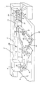
- the drawing shows a schematic, perspective Partial view of a portal machine with a processing station, on which the edging of plate-shaped Workpieces can be made.
- the drawing shows a support 1 that here is part of a portal, which is arranged fixed is, but also in the direction of one of the machine axes can be movable. Basically it can Support 1 also includes a boom support Act the machine in a different design.
- In Portal construction is the Support 1 with its two ends each hung on a stand 2.
- Support 1 has at least one of it lateral long sides a guide 3, along which different Aggregates, as in the drawing Milling units, not shown, arranged movably could be.
- the gluing unit 8 sits on the underside of a drive unit 7 which is movable on the longitudinal guide 3 of the support 1.
- the gluing unit 8 is on the drive unit 7 an axis A that is vertical, pivotable so the working side of the gluing unit 8 always the side of the respective surface to be coated Workpiece 5 is facing. So the gluing unit 8 after driving over a corner of the workpiece 5 in a square or rectangular version can be swiveled by 90 °.
- the relative movement between the workpiece 5 and the gluing unit 8 perpendicular to The direction of the longitudinal guide 3 on the support 1 is either by moving the processing table 4 or the Supportes 1 perpendicular to its length. Become with the gluing unit 8 curly or curved Narrow sides of workpieces coated, accordingly, constant swiveling of the gluing unit 8 are provided.
- the gluing unit has on the side facing away from the working side 8 a feed device 10, the each to be processed edge strips 9 and depending on the progress of the edging process.
- the edge strip 9 is from a stock of the respective Edge material deducted, which is in one Magazine 11 is located.
- the magazine 11 be movable with support 1 or support 1. It can be next to the stand 2 or next to the processing table 4 be arranged in a fixed position, depending on whether to do it with a transverse support 1 Has. From the magazine 11 that runs to the length of the each edge strip 9 required to be cut to length first by a clipping device 12 which is attached to the magazine 11.
- the cutting device 12 can be used to take over the trimmed edge strip 9 be approached by an intermediate conveyor 13, the movable on its own guide 21 at portal 1 is.
- a support device prevents in Shape of a support arm 14 an annoying sag of the edge strip 9, which in that area between the intermediate conveyor 13 and the feeding device 10 retractable on the gluing unit 8 at a suitable point and / or is pivotable.
- the support arm 14 consists of two arm parts 15 and 16, of which the inner arm part 15 either clamped on a suitable machine part or is attached to the intermediate conveyor 13.
- the outer arm part 16 articulated about a vertically extending axis B.
- the swivel drive takes place via a e.g. pneumatic or hydraulic cylinder 17, the attacks the outer arm part 16 and on the other hand on a Console 25 on the arm part 16, which is immovably attached is supported.
- a Console 25 on the arm part 16 which is immovably attached is supported.
- the outer arm part 16 can also in other ways movably arranged on the first, inner arm part 15 be, in particular there is a linear movement of the outer Arm part 16 into consideration. So the inner arm part 15 and the outer arm part 16 telescopically with each other be trained.
- the pivot cylinder 17 is controlled so that the Guide plate 18 with its upper sliding surface 19 den Edge strips 9 supported where a sag on would be most disturbing.
- the guide plate moves 18 in a horizontal plane, which in any case is above the workpiece level to prevent collisions.
- the workpiece level here is the level in which the tops of the workpieces in question 5 lie.
- a guide roller 20 At the end of the outer arm part 16 is a guide roller 20 stored, the axis of rotation C in the normal position is oriented vertically or slightly inclined.
- This Guide roller 20 acts in the manner of a deflection roller for the edging strip 9 and ensures that the edging strip 9 not from the sliding surface 19 of the guide plate 18 slides down. That is why the leadership role 20 near that corner area of the guide plate 18 arranged over the edge strips 9 would otherwise slip off.
- the guide plate 18 is on with its sliding surface 19 arranged at such a level that it is the intermediate conveyor 13 and / or drive under the gluing unit 8 can. Since this is basically a collision with the guide roller projecting upward on the guide plate 18 20 cannot be avoided is the leading role 20 foldable, against the force of one Spring, like a torsion spring that strives the guide roller 20 with its axis C in a vertical position to keep.
- the support plate 22 can in the Direction of travel of the intermediate conveyor 13 a considerable Have length and is still towards the magazine 11 can be moved without collision because it is attached to the magazine 11 can pass under the above cutting device 12.
- On the support plate 22 can the edge strip 9 as well stand up on the guide plate 18 on the support arm 4, this prevents the edge strip from twisting 9. Since the edge strip 9 due to inner Tension can bend easily, creating the end of the edge strip 9 over the longitudinal edge of the support plate 22 could preside, a precaution has been taken to prevent this. At least that's the way it is An upstand 23 on the long side of the support plate 22 provided at which the end of the edge strip 9 can support and also stiffened the support plate 22. In the same way, if necessary such stop also on the guide plate 18 of the Support arm 14 may be provided. Conversely, just like the guide plate 18 on the support arm 14, the support plate 22 on the intermediate conveyor 13 against the force of a spring have inclinable guide roller 20.
Landscapes
- Life Sciences & Earth Sciences (AREA)
- Engineering & Computer Science (AREA)
- Mechanical Engineering (AREA)
- Wood Science & Technology (AREA)
- Forests & Forestry (AREA)
- Folding Of Thin Sheet-Like Materials, Special Discharging Devices, And Others (AREA)
- Feeding Of Workpieces (AREA)
- Coating Apparatus (AREA)
Abstract
Description
Claims (17)
- Maschine zum Bearbeiten der Schmalflächenseiten plattenförmiger Werkstücke, wie Platten für den Möbel- oder Innenausbau, mit einem Verleimaggregat (8) zum Anleimen von Kantenstreifen (9) an die Werkstück-Schmalflächen-seiten, welches an einem Support (1) entlang eines auf einem darunter befindlichen Bearbeitungsplatz angeordneten Werkstücks (5) in einer Horizontalebene verfahrbar ist, und ferner mit einem Magazin (11) für das Kantenstreifenmaterial, dem eine Kappeinrichtung (12) zum Ablängen des jeweiligen Kantenstreifens (9) nachgeordnet ist und zwischen dem und dem Verleimaggregat (8) ein Zwischenförderer (13) für das Übergeben des jeweiligen Kantenstreifens (9) an das Verleimaggregat (8) angeordnet ist, der mit einer Einzugvorrichtung (10) für den Kantenstreifen (9) am Verleimaggregat (8) zusammenwirkt, wozu das Verleimaggregat (8) und der Zwischenförderer (13) relativ zueinander verfahrbar sind,
dadurch gekennzeichnet, daß im Bereich der Förderstrecke des Kantenstreifens (9) zwischen dem Zwischenförderer (13) und dem Verleimaggregat (8) und/oder zwischen dem Magazin (11) und dem Zwischenförderer (13) eine den Kantenstreifen (9) unterfangende Stützvorrichtung (14, 22) vorhanden ist. - Maschine nach Anspruch 1,
dadurch gekennzeichnet, daß die zumindest eine Stützvorrichtung (14, 22) mitfahrend am Zwischenförderer (13) oder am Verleimaggregat (8) oder am Magazin (11) angeordnet ist. - Maschine nach Anspruch 1 oder 2,
dadurch gekennzeichnet, daß sich die zumindest eine Stützvorrichtung (14, 22) oberhalb der den Bearbeitungsplatz (24) überspannenden Werkstückebene befindet. - Maschine nach einem der Ansprüche 1 - 3,
dadurch gekennzeichnet, daß die zumindest eine Stützvorrichtung aus einem oberhalb des Bearbeitungsplatzes (24) vorkragenden Stützarm (14) besteht, der ein unbeweglich befestigtes Armteil (15) und ein daran bewegliches Armteil (16) aufweist. - Maschine nach Anspruch 4,
dadurch gekennzeichnet, daß das bewegliche Armteil (16) um eine vertikale Achse (A) schwenkbar am befestigten Armteil (15) angelenkt ist. - Maschine nach Anspruch 4,
dadurch gekennzeichnet, daß das bewegliche Armteil (16) am unbeweglich befestigten Armteil (15) linear verschieblich angeordnet ist. - Maschine nach einem der Ansprüche 4 - 6,
dadurch gekennzeichnet, daß das unbeweglich befestigte Armteil (15) des Stützarms (14) am Zwischenförderer (13) angeordnet ist. - Maschine nach einem der Ansprüche 4 - 7,
dadurch gekennzeichnet, daß am beweglichen Armteil (16) des Stützarms (14) eine nach oben hin freiliegende Gleitfläche (19) als Auflagerfläche für den Kantenstreifen (9) angeordnet ist. - Maschine nach Anspruch 8,
dadurch gekennzeichnet, daß die Gleitfläche (19) von der Oberseite einer an den Stützarm (14) angesetzten Führungsplatte (18) gebildet ist. - Maschine nach Anspruch 8 oder 9,
dadurch gekennzeichnet, daß am Stützarm (14) zumindest eine Führungsrolle (20) für den Kantenstreifen (9) gelagert ist, welche mit ihrer Achse (C) aufrecht angeordnet ist und die über die Gleitfläche (19) nach oben vorsteht. - Maschine nach Anspruch 10,
dadurch gekennzeichnet, daß die Führungsrolle (20) am Stützarm (14) gegen die Kraft einer sie in die aufrechte Lage rückstellenden Feder beim Auflaufen auf ein Hindernis umlegbar ist. - Maschine nach einem der Ansprüche 4 - 11,
dadurch gekennzeichnet, daß die aus dem Stützarm (14) bestehende Stützvorrichtung zwischen dem Zwischenförderer (13) und dem Kantenanleimaggregat (8) angeordnet ist. - Maschine nach einem der Ansprüche 4 - 11,
dadurch gekennzeichnet, daß die aus dem Stützarm (14) bestehende Stützvorrichtung zwischen dem Zwischenförderer (13) und dem Magazin (11) angeordnet ist. - Maschine nach einem der Ansprüche 1 - 3,
dadurch gekennzeichnet, daß die Stützvorrichtung aus einer horizontalen Stützplatte (22) besteht, die mitfahrend am Zwischenförderer (13) angeordnet ist und daran an der dem Magazin (11) zugewandten Seite vorsteht. - Maschine nach Anspruch 14,
dadurch gekennzeichnet, daß die Stützplatte (22) am Zwischenförderer (13) sich in Horizontalrichtung erstreckt. - Maschine nach Anspruch 14 oder 15,
dadurch gekennzeichnet, daß das Magazin (11) an seiner Auslaßseite für den jeweiligen Kantenstreifen (9) eine Kappvorrichtung (12) mit einem Auslaß hat, der oberhalb der Verfahrebene der Stützplatte (22) am Zwischenförderer (13) liegt und von dieser Stützplatte (22) unterfahrbar ist. - Maschine nach einem der Ansprüche 14 - 16,
dadurch gekennzeichnet, daß die Stützplatte (22) an zumindest einer der in der Förderrichtung des jeweiligen Kantenstreifens (9) sich erstreckenden Kanten eine Aufkantung (23) hat.
Applications Claiming Priority (2)
| Application Number | Priority Date | Filing Date | Title |
|---|---|---|---|
| DE2001124694 DE10124694C2 (de) | 2001-05-18 | 2001-05-18 | Maschine zum Bearbeiten plattenförmiger Werkstücke mit einem Verleimaggregat |
| DE10124694 | 2001-05-18 |
Publications (3)
| Publication Number | Publication Date |
|---|---|
| EP1258329A2 true EP1258329A2 (de) | 2002-11-20 |
| EP1258329A3 EP1258329A3 (de) | 2006-05-24 |
| EP1258329B1 EP1258329B1 (de) | 2007-08-15 |
Family
ID=7685565
Family Applications (1)
| Application Number | Title | Priority Date | Filing Date |
|---|---|---|---|
| EP20020010004 Expired - Lifetime EP1258329B1 (de) | 2001-05-18 | 2002-05-04 | Maschine zum Bearbeiten plattenförmiger Werkstücke mit einem Verleimgerät |
Country Status (3)
| Country | Link |
|---|---|
| EP (1) | EP1258329B1 (de) |
| DE (2) | DE10124694C2 (de) |
| ES (1) | ES2291392T3 (de) |
Cited By (2)
| Publication number | Priority date | Publication date | Assignee | Title |
|---|---|---|---|---|
| EP2253440A3 (de) * | 2009-05-18 | 2011-08-31 | Homag Holzbearbeitungssysteme AG | Zufuhrvorrichtung |
| EP2505322A1 (de) * | 2011-03-29 | 2012-10-03 | Homag Holzbearbeitungssysteme AG | Maschinensystem |
Families Citing this family (3)
| Publication number | Priority date | Publication date | Assignee | Title |
|---|---|---|---|---|
| WO2023147635A1 (pt) * | 2022-02-03 | 2023-08-10 | Da Silva Nelson | Configuração aplicada em máquina coladeira e sua disposição construtiva de múltiplos coleiros |
| DE102022118498B3 (de) | 2022-07-25 | 2023-10-26 | Oav Equipment And Tools, Inc. | Kantenanleimmaschine |
| EP4706923A1 (de) * | 2024-09-05 | 2026-03-11 | Tecno Logica S.R.L. | Verfahren zum kantenumleimen von panelen und ein kantenumleimkopf, der das verfahren ausführt |
Family Cites Families (10)
| Publication number | Priority date | Publication date | Assignee | Title |
|---|---|---|---|---|
| US3833036A (en) * | 1970-01-26 | 1974-09-03 | D Marvosh | Machine for making tabletops |
| DE7031331U (de) * | 1970-08-21 | 1971-09-02 | Klessmann Ima Norte Maschfab | Trommelmagazin fuer furnierkanten-maschine. |
| DE8002483U1 (de) * | 1980-01-31 | 1980-07-10 | Hornberger Maschinenbaugesellschaft Mbh + Co Kg, 7294 Schopfloch | Vorrichtung zum zufuehren von band- oder streifenmaterial zu einer kantenanleimmaschine |
| DE3517194A1 (de) * | 1985-05-13 | 1986-11-13 | Heinrich Brandt Maschinenbau GmbH, 4920 Lemgo | Verfahren und vorrichtung zum bearbeiten von kanten von plattenfoermigen werkstuecken |
| DE8631175U1 (de) * | 1986-11-21 | 1987-04-02 | Heinrich Brandt Maschinenbau GmbH, 4920 Lemgo | Vorrichtung zum Bearbeiten von Kanten von plattenförmigen Werkstücken |
| DE8711138U1 (de) * | 1987-08-17 | 1987-10-01 | Werner, Johannes, 4790 Paderborn | Vorrichtung zum Einpressen von Profilleisten in Möbelplatten |
| DE3914461C2 (de) * | 1989-05-02 | 1997-03-27 | Klessmann Ima Norte Maschfab | Maschine zum Anleimen von Kantenmaterial an plattenförmige Werkstücke |
| US5246533A (en) * | 1991-11-05 | 1993-09-21 | Marunaka Kakoki Co., Ltd. | Apparatus for press-bonding tape onto edges of workpiece |
| US5992488A (en) * | 1995-08-04 | 1999-11-30 | Bortolini Engineering | Flanging and trimming machine of panels |
| IT1295655B1 (it) * | 1997-10-31 | 1999-05-24 | Scm Group Autec Division Spa | Macchina bordatrice. |
-
2001
- 2001-05-18 DE DE2001124694 patent/DE10124694C2/de not_active Expired - Fee Related
-
2002
- 2002-05-04 ES ES02010004T patent/ES2291392T3/es not_active Expired - Lifetime
- 2002-05-04 DE DE50210674T patent/DE50210674D1/de not_active Expired - Lifetime
- 2002-05-04 EP EP20020010004 patent/EP1258329B1/de not_active Expired - Lifetime
Cited By (2)
| Publication number | Priority date | Publication date | Assignee | Title |
|---|---|---|---|---|
| EP2253440A3 (de) * | 2009-05-18 | 2011-08-31 | Homag Holzbearbeitungssysteme AG | Zufuhrvorrichtung |
| EP2505322A1 (de) * | 2011-03-29 | 2012-10-03 | Homag Holzbearbeitungssysteme AG | Maschinensystem |
Also Published As
| Publication number | Publication date |
|---|---|
| DE10124694C2 (de) | 2003-04-03 |
| DE50210674D1 (de) | 2007-09-27 |
| ES2291392T3 (es) | 2008-03-01 |
| EP1258329A3 (de) | 2006-05-24 |
| DE10124694A1 (de) | 2002-11-28 |
| EP1258329B1 (de) | 2007-08-15 |
Similar Documents
| Publication | Publication Date | Title |
|---|---|---|
| DE69606615T2 (de) | Vorrichtung zum anbringen und beschneiden von kantenmaterial an plattenförmigen werkstücken | |
| EP0229668A2 (de) | Schneidmaschine für plattenförmige Werkstücke | |
| EP1836021A1 (de) | Verfahren zum laserscneiden von materialtafeln, insbesondere metallblechen, sowie schneidanlage zur durchführung des verfahrens | |
| DE3527902A1 (de) | Vorrichtung und verfahren zum stapeln und/oder palettieren von insbesondere duennen produkten eines druckereibetriebes | |
| DE20203938U1 (de) | Bearbeitungsmaschine zum wenigstens teilweisen konturenabhängigen Ausschneiden oder Fräsen | |
| DE1628991C3 (de) | Maschine zum Herstellen von genuteten Werkstücken für die Möbelkorpusfertigung | |
| EP1136206B1 (de) | Schwenkfräsmaschine | |
| DE2330476C3 (de) | Plattenfertigaufteileinrichtung | |
| EP1258329B1 (de) | Maschine zum Bearbeiten plattenförmiger Werkstücke mit einem Verleimgerät | |
| DE2740673A1 (de) | Kreissaegemaschine fuer platten, plattenpakete o.dgl. | |
| DE3033334A1 (de) | Vorrichtung zum herstellen von laenglichen konstruktionsteilen | |
| DE19632143C2 (de) | Maschine zum Schleifen von Holzrahmen | |
| DE19914580A1 (de) | Verfahren zum Handhaben von Stapeln von Papier, Pappe o. dgl. an einer Schneidmaschine | |
| EP0930120B1 (de) | Trennsäge mit einem verstellbaren Auflagetisch | |
| DE8812624U1 (de) | Holzbearbeitungsmaschine, insbesondere Kehlmaschine | |
| DE3544899A1 (de) | Stuetzvorrichtung fuer abzutrennende streifen bei scher- bzw. schneidmaschinen | |
| CH665159A5 (de) | Schleifmaschine. | |
| DE4235240C2 (de) | Verfahren zur Herstellung und Bearbeitung paralleler Gehrungen an den beiden Stirnflächen langgestreckter Hölzer und Doppelendprofiler zur Durchführung dieses Verfahrens | |
| EP0571816B1 (de) | Kantenanleimmaschine | |
| DE9103838U1 (de) | Schweißvorrichtung für rechteckige Rahmen, insbesondere Fensterrahmen | |
| DE2545274A1 (de) | Verfahren und maschinenanlage zur herstellung von keilzinkenverbindungen fuer die holzlaengsverleimung | |
| DE4217291C1 (de) | Kantenanleimmaschine | |
| DE8033805U1 (de) | Vorrichtung zur bearbeitung plattenfoermiger werkstuecke | |
| DE2423869B2 (de) | Vorrichtung zum querschneiden einer textilbahn | |
| AT399467B (de) | Verfahren und vorrichtung zum herstellen von dünnen steinplatten |
Legal Events
| Date | Code | Title | Description |
|---|---|---|---|
| PUAI | Public reference made under article 153(3) epc to a published international application that has entered the european phase |
Free format text: ORIGINAL CODE: 0009012 |
|
| AK | Designated contracting states |
Kind code of ref document: A2 Designated state(s): AT BE CH CY DE DK ES FI FR GB GR IE IT LI LU MC NL PT SE TR |
|
| AX | Request for extension of the european patent |
Free format text: AL;LT;LV;MK;RO;SI |
|
| PUAL | Search report despatched |
Free format text: ORIGINAL CODE: 0009013 |
|
| AK | Designated contracting states |
Kind code of ref document: A3 Designated state(s): AT BE CH CY DE DK ES FI FR GB GR IE IT LI LU MC NL PT SE TR |
|
| AX | Request for extension of the european patent |
Extension state: AL LT LV MK RO SI |
|
| 17P | Request for examination filed |
Effective date: 20060415 |
|
| AKX | Designation fees paid |
Designated state(s): DE ES FR IT |
|
| GRAP | Despatch of communication of intention to grant a patent |
Free format text: ORIGINAL CODE: EPIDOSNIGR1 |
|
| GRAS | Grant fee paid |
Free format text: ORIGINAL CODE: EPIDOSNIGR3 |
|
| GRAA | (expected) grant |
Free format text: ORIGINAL CODE: 0009210 |
|
| AK | Designated contracting states |
Kind code of ref document: B1 Designated state(s): DE ES FR IT |
|
| RIN1 | Information on inventor provided before grant (corrected) |
Inventor name: GOETZ, FRIEDER Inventor name: SCHMID, JOHANNES |
|
| REF | Corresponds to: |
Ref document number: 50210674 Country of ref document: DE Date of ref document: 20070927 Kind code of ref document: P |
|
| REG | Reference to a national code |
Ref country code: ES Ref legal event code: FG2A Ref document number: 2291392 Country of ref document: ES Kind code of ref document: T3 |
|
| PLBE | No opposition filed within time limit |
Free format text: ORIGINAL CODE: 0009261 |
|
| STAA | Information on the status of an ep patent application or granted ep patent |
Free format text: STATUS: NO OPPOSITION FILED WITHIN TIME LIMIT |
|
| 26N | No opposition filed |
Effective date: 20080516 |
|
| PGFP | Annual fee paid to national office [announced via postgrant information from national office to epo] |
Ref country code: FR Payment date: 20080529 Year of fee payment: 7 |
|
| PGFP | Annual fee paid to national office [announced via postgrant information from national office to epo] |
Ref country code: ES Payment date: 20090408 Year of fee payment: 8 |
|
| REG | Reference to a national code |
Ref country code: FR Ref legal event code: ST Effective date: 20100129 |
|
| PG25 | Lapsed in a contracting state [announced via postgrant information from national office to epo] |
Ref country code: FR Free format text: LAPSE BECAUSE OF NON-PAYMENT OF DUE FEES Effective date: 20090602 |
|
| REG | Reference to a national code |
Ref country code: ES Ref legal event code: FD2A Effective date: 20110714 |
|
| PG25 | Lapsed in a contracting state [announced via postgrant information from national office to epo] |
Ref country code: ES Free format text: LAPSE BECAUSE OF NON-PAYMENT OF DUE FEES Effective date: 20110704 |
|
| PG25 | Lapsed in a contracting state [announced via postgrant information from national office to epo] |
Ref country code: ES Free format text: LAPSE BECAUSE OF NON-PAYMENT OF DUE FEES Effective date: 20100505 |
|
| PGFP | Annual fee paid to national office [announced via postgrant information from national office to epo] |
Ref country code: IT Payment date: 20110520 Year of fee payment: 10 Ref country code: DE Payment date: 20110524 Year of fee payment: 10 |
|
| PG25 | Lapsed in a contracting state [announced via postgrant information from national office to epo] |
Ref country code: IT Free format text: LAPSE BECAUSE OF NON-PAYMENT OF DUE FEES Effective date: 20120504 |
|
| REG | Reference to a national code |
Ref country code: DE Ref legal event code: R119 Ref document number: 50210674 Country of ref document: DE Effective date: 20121201 |
|
| PG25 | Lapsed in a contracting state [announced via postgrant information from national office to epo] |
Ref country code: DE Free format text: LAPSE BECAUSE OF NON-PAYMENT OF DUE FEES Effective date: 20121201 |